Page is loading ...

Ora Bolt Through Fixing
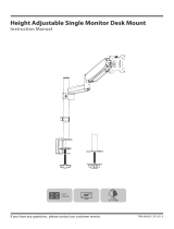
Installation Guide
AW-FB
COMPONENT CHECKLIST
Clamp Plate (x1)
Clamp Bar (x1)
Arm Spigot (x1)
M8 Stud Bolt (x1)
M8 Flange Nut (x1)
No portion of this document or any artwork contained herein should be
reproduced in any way without the express written consent of Atdec Pty
Ltd. Due to continuing product development, the manufacturer reserves
the right to alter specifications without notice. ©20231006
WARRANTY
10 Years Limited
TOOLS REQUIRED
4mm Hex Key (supplied with Ora arm)
8.5mm (or 11/32”) drill bit
Power Drill
13mm Spanner
Phillips head screwdriver
CAPACITY
2 - 8kg (4.4 - 17.6lb)
Up to 35” (curved or flat)
(Larger monitors within the weight
capacity may be compatible, please
contact Atdec for advice).
Weight:
Display Size:
IMPORTANT INFORMATION
•Install Ora Accessories as per these installation
instructions.
•The manufacturer accepts no responsibility for
incorrect installation.
•The product is compatible with grommet hole sizes
up to 80mm (3.15”)
•The product is compatible with desk thicknesses
from 0-55mm (0-2.2”).
•Do not over-tighten screws and adjustment points
on product.
•This product is not suitable for outdoor use.
•Do not use this product for mobile applications.
•Please ensure desk structure and mounting surface
are of sufficient strength to support this product and
mounted equipment.

1 For bolt through installations,
drill hole in the work surface
Drill the hole using a suitable drill bit. Ensure the
hole is drilled perpendicular to the work surface
and the edges of the clamp are positioned fully
on the desk.
1.2
Mark out hole
position on the
work surface.
Use Clamp Plate
as a template.
1.1
USER
40mm (1 ⅔”)
minimum
8.5 mm (1⅓2”)
Desk
Thickness
18 - 40mm
(¾ - 1½”)
TIP
When positioning the desk clamp, offset the
clamp to the left or right of the seating position.
The monitor will then be centred for the user.
100mm
(4”)
2 Attach Arm Spigot to
Clamp Plate
Hold Arm Spigot and Clamp
Plate together, locating the
dimple in the slot, before
hand tightening the screw
into the spigot.
HINT!
Screw M8 Stud Bolt through Clamp Plate into
Arm Spigot.
Tighten firmly with 4mm
Hex Key supplied with Arm.
2.2
3 Attach plate assembly to desk
TIP
Support plate while tightening to maintain the
correct orientation on the work surface.
Place Clamp Bar over M8 Stud Bolt under the desk
as illustrated and secure Flange Nut with spanner.

CONTINUE ORA MONITOR
ARM ASSEMBLY
COMPONENT CHECKLIST
VESA Plate (x1)
Upper Link (x1)
Lower Link(x1)
4mm
Hex Key
(x1)
M4x10
Screw
(x4)
Security
Screw
(x1)
Ora monitor arms sold separately. If chosen arm
has a supplied desk clamp, retain for future use.
3.1
3 Attach Lower Link to Clamp
360°
180°
IMPORTANT INFORMATION
•Install Ora Monitor Arm as per these installation
instructions.
•The manufacturer accepts no responsibility for
incorrect installation.
•Do not over-tighten screws and adjustment points
on product.
•This product is not suitable for outdoor use.
•Do not use this product for mobile applications.
•Deep devices (such as all-in-one PCs), VESA
mounted accessories (such as mini PC brackets and
mounts), and offset VESA locations exert additional
leverage that can exceed the capacity of the mount
even though the monitor weight may be within the
stated range. Please contact Atdec if you would like
further information.
•Suits displays with VESA mounting hole patterns
75x75 and 100x100. Spacer kit (sold separately) may
be required for recessed 75x75 hole patterns.
•Periodic adjustment to counterbalance and tilt
tension may be required.
3.3 Select rotation setting
360°
3.2
360°
180°
360°
180°
180°
NOTE
Pivot lower link to the
forward position over the
desk before selecting
180˚ rotation
setting.
OR

PRESS
DOWN
IMPORTANT
Ensure plastic sleeve
is fitted on lower link
4 Attach Upper Link
4.1
Using the 4mm hex
key, tighten set screw
until joint rotation is
firm and smooth
4.3
Press down firmly to
ensure the upper link
is fully located onto
the lower link
CAUTION!
Check Cover Strip
To inspect cover
strip, fully lower the
upper link . If
damaged or missing,
stop installation and
contact Atdec for
assistance.
4.4
PUSH DOWN
AND HOLD
4.2
5 Mount Monitor
Attach VESA Plate using
supplied M4x10 screws.
Attach monitor
to arm
5.1
5.2
100mm
75mm
100mm
75mm
5.3
NOTE
Recessed 75x75mm
VESA interfaces will
require a spacer kit
(sold separately)
Check VESA mounting
compatibility of monitor
NOTE
For other sizes, use
suitable adaptor plate
(sold separately).
Ensure screw length
suits the monitor
TOO
LONG
OK
TOO
SHORT
Click
6 Adjustments
6.1 Tilt Tension
6.2 Monitor Rotation Tension (optional)
If required, adjust tilt
tension using 4mm
hex key. (do not
over-tighten)
Adjust rotation tension
using 4mm hex key.
NOTE
Support the
screen while
adjusting
NOTE
Adjustment may
only be required
for ultrawide
monitors
HOLDS POSITION
HOLDS POSITION
DRIFTS
DROOPS FORWARD
TIGHTEN
TIGHTEN
LOOSEN
LOOSEN

6.3 Counterbalance Adjustment
Increase
tension
Reduce
tension
TIP
For best results,
adjust
counterbalance
with the arm and
monitor in the
position shown.
Adjustment is
easiest when the
monitor is in the
highest position.
TIP
When installing multiple arms with the same monitor,
use the setting on the counterbalance adjustment
gauge to quickly ‘pre-set’ other arms (fine-tuning may
be required after pre-setting).
Using the 4mm hex key,
adjust counterbalance
to suit the monitor
weight
DROOPS BOUNCES UP HOLDS
POSITION
COUNTER-
BALANCE
ADJUSTMENT
SCREW
COUNTER-
BALANCE
ADJUSTMENT
GAUGE
Lighter
Monitors
Heavier
Monitors
6.4 Security Screw (optional)
If desired, once
monitor is
attached to the
arm, install the
security screw.
This disables the
release switch,
preventing theft.
Click
SLIDE
6.5 Removing Monitor
LIFT
7 Cable Management
7.1 Overview
NOTE
Ensure enough cable
slack is given to
allow for movement
of the monitor
NOTE
Allow 1.2m of cable from the work surface to the
monitor. Add additional cable length to route the
cable from the work surface to the computer.
Go to
6.4
Go to
6.3
If desired,
store hex key
in lower link
7.2

7.3 Route Cables Through Upper Link
PULL
S
L
I
D
E
S
L
I
D
E
TUCK
TUCK
Tuck cables behind
tabs inside lower link.
7.4
Remove lower link
cable cover.
7.6
SLIDE
Re-attach lower link
cable cover.
7.5
SLIDE
/