
Electrical Quick Start
1) Attach matched 50Ω SMA cables from a 50Ω oscillo-
scope to OUT+ and OUT-. Set the oscilloscope to
20mV/div and 200ps/div. A single-ended evaluation
is acceptable; however, the cable not terminated
into the scope should be terminated with a 50Ω load
at the end of the cable.
2) Ensure that there is a shunt across the VCCS pins.
(Remove shunt for 5.0V operation.)
3) Attach ground to either side of the GND 2-pin
header and +3.3V (or +5.0V) to either side of the
VCCD 2-pin header.
4) Connect a 50Ω cable between the output of a 50Ω
source and the input of the EV kit. Set the source to
produce a 2.0Vp-p, 2.5Gbps 1-0 pattern.
5) Adjust R9 and R6 to produce a DC current of 1mA
(1mA = 2.0Vp-p / 1kΩ / 2) through R7. This can be
verified by checking for a 1V drop across R7.
6) Verify that the input pattern is present at the output.
General Description
The MAX3866 evaluation kit (EV kit) is a fully assem-
bled, chip-on-board (COB) electrical demonstration kit.
It provides easy evaluation of the MAX3866 2.5Gbps,
+3.3V combined transimpedance/limiting amplifier.
Features
♦ Easy +3.3V or +5.0V Electrical Evaluation of
MAX3866
♦ Evaluation of Adjustable Loss-of-Power (LOP)
♦ Fully Assembled and Tested
♦ EV Kit Designed for 50Ω I/O Interface
Evaluates: MAX3866
MAX3866 Evaluation Kit
________________________________________________________________
Maxim Integrated Products
1
19-1451; Rev 0; 3/99
SUPPLIER PHONE FAX
AVX 803-946-0690 803-626-3123
Component List
Central Semiconductor 516-435-1110 516-435-1824
Murata 814-237-1431 814-238-0490
Zetex 516-543-7100 516-864-7630
PART
MAX3866EVKIT -40°C to +85°C
TEMP. RANGE
For free samples & the latest literature: http://www.maxim-ic.com, or phone 1-800-998-8800.
For small orders, phone 1-800-835-8769.
Ordering Information
Component Suppliers
SMA connectors (edge mount)
E.F. Johnson 142-0701-801 or
Digi-Key J502-ND
3
INPUT (J1),
OUT+ (J4),
OUT- (J5)
LED1CR1
1MΩ potentiometer1R9
1kΩ potentiometer1R6
49.9Ω, 1% resistors (0402)2R5, R8
1kΩ, 1% resistors (0402)2R3, R7
DESIGNATION
150Ω, 1% resistor (0402)1R2
500Ω potentiometer1R1
1µH inductor
Coilcraft 1008CS-102 XKBB, 10%
1L1
Leave site open0
C9, J2, J3, L2,
R4, R10, R11,
R12, TP2, TP3
100nF, 25V min, 10% ceramic capaci-
tors (0603)
7
C1, C2, C3,
C5–C8
DESCRIPTIONQTY
Test point
Mouser 151-203
1LOP
2-pin headers (0.1" centers)
Digi-Key S1012-36-ND
3
VCCS, VCCD,
GND
Shunt (installed)
Digi-Key S9000-ND
1VCCS
MAX3866E/D1U1
MAX3866 circuit boards, Rev. B2None
MAX3866 data sheet1None
MAX3866 EV kit data sheet1None
0.5" spacers3None
Screws for the spacers6None
Note: Please indicate that you are using the MAX3866 when
ordering from these suppliers.

Evaluates: MAX3866
MAX3866 Evaluation Kit
2 _______________________________________________________________________________________
Adjustment and Control Description
CONTROL NAME FUNCTION/MANIPULATION
VCCD VCCD
Power-Supply Voltage. Both pins of this dual-pin header are the same
point.
VCCS VCCS
Power-Supply Select Jumper. Do not apply any external voltages at
this point. Both pins of this 2-pin header are not connected electrically.
Depending on what the operating voltage is, either place a shunt at
VCCS or remove the shunt from VCCS. When evaluating at 3.14V to
3.47V, ensure that there is a shunt on VCCS. If the evaluation voltage is
5.0V to 5.5V, remove this shunt and place a 100nF capacitor in location
C8. (EV kit is shipped with 100nF in the C8 location; see
Figure 1
.)
J1 INPUT
Single-Ended Input, 3mVp-p to 2.5Vp-p range. This translates into a
current of 3µA to 2.5mA, respectively (voltage at input) / (R3 = 1kΩ).
Note that the EV kit input is terminated for a 50Ω source.
J4, J5 OUTP, OUTM
Signal Outputs (AC-coupled). Note that the EV kit outputs are designed
for 50Ω termination.
R6, R9 —
Micro and Macro Current Adjustment. Simulates the average DC
current portion of a diode. The amount of current that should be set
through these potentiometers is calculated by the formula (AC current
into MAX3866) / 2 = DC bias current.
CR1 DIODE
LOP is active high. Therefore, when an LOP condition exists, the LED
will be off.
TP1 LOP
TTL Output, active high. Probe this test point only with a high-imped-
ance lead.
R1 —
Sets the LOP Threshold. For normal operation, Maxim recommends R8
+ R1 = 510Ω. However, if other values are desired, please refer to the
Typical Operating Characteristics
section (Assert/Deassert vs. R
PD
) of
the MAX3866 data sheet.
SJ2 —
Solder Jumper. For normal operation, ensure that this solder jumper is
open.

Evaluates: MAX3866
MAX3866 Evaluation Kit
_______________________________________________________________________________________ 3
CHF-
FIL-
GND
GND
R3
1k
R6
1k
SJ2
SOLDER JUMPER
OPEN
R9
1M
L1
1µH
L2
OPEN
R11
OPEN
R12
OPEN
C9
OPEN
R10
OPEN
Z
O
= 50
2
1
1
1
F
2
2
1
F
F1
2
2
3
GND
GND
3
C3
100nF
R7
1k
INPUT
J1
SMA
ZTEST1
J2
SMA
ZTEST2
J3
SMA
R5
50Ω
LINE TERMINATION
GND
IN+
IN-
GND
N.C.
R8
50Ω
R1
500Ω
C2
100nF
1
3
2
GND
OUT+
OUT-
GND
LOP
CHF+ VCCS VCCS VCCD VCCD
LOP
R2
150Ω
R4
OPEN
CR1
DIODE
VCCD
2
1
GND
P2
VCCD
P1 (3.13V... 3.47V OR
4.5V....5.5V)
2
VCCD
C8
100nF
VCCS
(C8 IS NOT REQUIRED
IN 3.3V OPERATION.)
C7
100nF
C1
100nF
12
1
C5
100nF
OUT+
J4
SMA
OUT-
J5
SMA
1
2
1
2
C6
100nF
PDC INV GND GND CPD- CPD+
MAX3866
U1
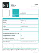
Figure 1. MAX3866 EV Kit Schematic

Evaluates: MAX3866
MAX3866 Evaluation Kit
4 _______________________________________________________________________________________
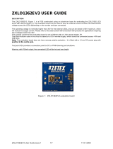
Figure 2. MAX3866 EV Kit Component Placement Guide—
Component Side
1.0"

Evaluates: MAX3866
MAX3866 Evaluation Kit
_______________________________________________________________________________________ 5
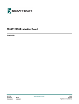
Figure 3. MAX3866 EV Kit PC Board Layout—Component Side
Figure 4. MAX3866 EV Kit—Ground Plane
1.0"
1.0"

Evaluates: MAX3866
MAX3866 Evaluation Kit
6 _______________________________________________________________________________________
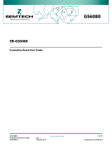
Figure 5. MAX3866 EV Kit—Power Plane Figure 6. MAX3866 EV Kit PC Board Layout—Solder Side
1.0"1.0"

Evaluates: MAX3866
MAX3866 Evaluation Kit
_______________________________________________________________________________________ 7
Figure 7. MAX3866 EV Kit—Bond Diagram
1.0"
HF23Z

Maxim cannot assume responsibility for use of any circuitry other than circuitry entirely embodied in a Maxim product. No circuit patent licenses are
implied. Maxim reserves the right to change the circuitry and specifications without notice at any time.
8
_____________________Maxim Integrated Products, 120 San Gabriel Drive, Sunnyvale, CA 94086 408-737-7600
© 1999 Maxim Integrated Products Printed USA is a registered trademark of Maxim Integrated Products.
Evaluates: MAX3866
MAX3866 Evaluation Kit
Maxim cannot assume responsibility for use of any circuitry other than circuitry entirely embodied in a Maxim product. No circuit patent licenses are
implied. Maxim reserves the right to change the circuitry and specifications without notice at any time.
8
_____________________Maxim Integrated Products, 120 San Gabriel Drive, Sunnyvale, CA 94086 408-737-7600
© 1999 Maxim Integrated Products Printed USA is a registered trademark of Maxim Integrated Products.
NOTES
Maxim cannot assume responsibility for use of any circuitry other than circuitry entirely embodied in a Maxim product. No circuit patent licenses are
implied. Maxim reserves the right to change the circuitry and specifications without notice at any time.
8
_____________________Maxim Integrated Products, 120 San Gabriel Drive, Sunnyvale, CA 94086 408-737-7600
© 1999 Maxim Integrated Products Printed USA is a registered trademark of Maxim Integrated Products.
-
 1
1
-
 2
2
-
 3
3
-
 4
4
-
 5
5
-
 6
6
-
 7
7
-
 8
8


Ask a question and I''ll find the answer in the document
Finding information in a document is now easier with AI
Related papers
-
Maxim MAX31782 Quick start guide
-
-
-
-
-
Maxim MAX1455 User manual
-
-
-
-
Other documents
-
Analog Devices MAX34407EVKIT# Operating instructions
-
 HiB MAXIM Datasheet
-
 Zetex Semiconductors PLC ZXLD1362EV3 User manual
-
Philips SA5223 User manual
-
 Semtech EB-GS12190 Evaluation Board User guide
-
 Semtech EB-GS6080 Evaluation Board User guide
-
 Semtech GS2993 User manual
-
-
 Semtech GS2984 User guide
-
 Semtech EB-UHD-SDI Evaluation Board Kit User guide


