
SoftSurface
Installation & User’s Guide
Document Version 1.0.1, January 2019
SoftSurface Version 1.04
TelosAlliance.com

User Warnings and Cautions
The installation and service instructions in this manual are for use by qualied personnel only. To avoid electric
shock, do not perform any servicing other than that contained in the operating instructions unless you are qualied
to do so. Refer all servicing to qualied personnel.
This instrument has an autoranging line voltage input. Ensure the power voltage is within the specied range of 100-
240VAC. The ~ symbol, if used, indicates an alternating current supply.
This symbol, wherever it appears, alerts you to the presence of uninsulated, dangerous voltage inside the
enclosure – voltage which may be sufcient to constitute a risk of shock.
This symbol, wherever it appears, alerts you to important operating and maintenance instructions. Read the manual.
CAUTION: HAZARDOUS VOLTAGES
The instrument power supply incorporates an internal fuse. Hazardous voltages may still be present on some of the
primary parts even when the fuse has blown. If fuse replacement is required, replace fuse only with same type and
value for continued protection against re.
WARNING:
The product’s power cord is the primary disconnect device. The socket outlet should be located near the device and
easily accessible. The unit should not be located such that access to the power cord is impaired. If the unit is incorporated
into an equipment rack, an easily accessible safety disconnect device should be included in the rack design.
To reduce the risk of electrical shock, do not expose this product to rain or moisture. This unit is for indoor use only.
This equipment requires the free ow of air for adequate cooling. Do not block the ventilation openings on the rear
and sides of the unit. Failure to allow proper ventilation could damage the unit or create a re hazard. Do not place
the units on a carpet, bedding, or other materials that could interfere with any panel ventilation openings.
If the equipment is used in a manner not specied by the manufacturer, the protection provided by the equipment
may be impaired.
USA CLASS A COMPUTING DEVICE INFORMATION TO USER.
WARNING:
This equipment generates, uses, and can radiate radio-frequency energy. If it is not installed and used as directed
by this manual, it may cause interference to radio communication. This equipment complies with the limits for a
Class A computing device, as specied by FCC rules, part 15, subpart j, which are designed to provide reasonable
protection against such interference when this type of equipment is operated in a commercial environment.
Operation of this equipment in a residential area is likely to cause interference. If it does, the user will be required to
eliminate the interference at the user’s expense. Note: objectionable interference to TV or radio reception can occur
if other devices are connected to this device without the use of shielded interconnect cables. FCC rules require the
use of shielded cables.

CANADA WARNING:
“This digital apparatus does not exceed the Class A limits for radio noise emissions set out in the radio interference
regulations of the Canadian department of communications.”
“Le présent appareil numérique n’émet pas de bruits radioélectriques dépassant les limites applicables aux appareils
numériques (de Class A) prescrites dans le règlement sur le brouillage radioélectrique édicté par le ministère des
communications du Canada.”
CE CONFORMANCE INFORMATION:
This device complies with the requirements of the EEC council directives:
♦ 93/68/EEC (CE MARKING)
♦ 73/23/EEC (SAFETY – LOW VOLTAGE DIRECTIVE)
♦ 89/336/EEC (ELECTROMAGNETIC COMPATIBILITY)
Conformity is declared to those standards: EN50081-1, EN50082-1.
Trademarks, Patents, and Licenses
Axia is a trademark of TLS Corp. All other trademarks are the property of their respective holders.
All versions, claims of compatibility, trademarks, etc. of hardware and software products not made by The Telos
Alliance which are mentioned in this manual or accompanying material are informational only. The Telos Alliance
makes no endorsement of any particular product for any purpose, nor claims any responsibility for operation or
accuracy. We reserve the right to make improvements or changes in the products described in this manual which
may affect the product specications, or to revise the manual without notice.
This document and its content are copyrighted by TLS Corporation and may not be copied, reproduced, or
distributed in any form without expressed written permission.
Patent information can be found at www.TelosAlliance.com/legal
Updates
Axia SoftSurface features and operations are determined largely by software. The Telos Alliance strives to provide
the most stable and feature-rich software available. We encourage you to check for software updates from time to
time by visiting our website or by contacting us directly.
Feedback
We welcome feedback on any aspect of our products or this manual. In the past, many good ideas from users have
made their way into software revisions or new products. Please contact us with your comments or suggestions.

We support you…
By Phone/Fax
You may reach our Telos Support Team in emergencies by calling +1 216-622-0247. For billing questions or other
non-emergency technical questions, call +1 216-241-7225 between 9:00 AM to 5:00 PM USA Eastern Time,
Monday through Friday.
By Email
Non-emergency technical support is available at Support@TelosAlliance.com.
By Web
The Axia Web site has a variety of information that may be useful for product selection and support. The URL is
https://www.telosalliance.com/Axia .
Service
You must contact Telos Alliance before returning any equipment for factory service. We will need your unit’s serial
number, located on the back of the unit. We will issue a return authorization number, which must be written on the
exterior of your shipping container. Please do not include cables or accessories unless specically requested by the
Technical Support Engineer. Be sure to adequately insure your shipment for its replacement value. Packages without
proper authorization may be refused. US customers, please contact Telos Alliance Technical Support at +1-216-622-
0247. All other customers should contact local representative to make arrangements for service.
Warranty
For the latest Telos Alliance warranty, visit: telosalliance.com/warranty
Register your product
Register your product today to get the full benets of our warranty, support, and product updates.
telosalliance.com/product-registration/
The Telos Alliance
1241 Superior Ave. Cleveland, OH 44114 USA
+1 (216) 241-7225
For Telos Support:
24/7 telephone: +1 (216) 622-0247
Email: [email protected]
Web: telosalliance.com/support-request

Chapter One: What is SoftSurface?. . . . . . . . . . .1
Introduction . . . . . . . . . . . . . . . . . . . . . . 1
SoftSurface Interface . . . . . . . . . . . . . . . . .1
Channel Section . . . . . . . . . . . . . . . . . . 2
Control section . . . . . . . . . . . . . . . . . . 3
Chapter Two: Installation and Setup . . . . . . . . . . 7
Installation . . . . . . . . . . . . . . . . . . . . . . . 7
StudioEngine setup . . . . . . . . . . . . . . . . . .7
SoftSurface Setup . . . . . . . . . . . . . . . . . . . 8
Chapter Three: Using SoftSurface . . . . . . . . . . . 11
Using SoftSurface for Element remote control . . . . 11
Using SoftSurface with StudioEngine . . . . . . . .11
Source Prole Conguration . . . . . . . . . . . 12
Show Proles. . . . . . . . . . . . . . . . . . . .14
StudioEngine Setup . . . . . . . . . . . . . . . . . . 15
Conguring an IP address . . . . . . . . . . . . .15
HTML user interface. . . . . . . . . . . . . . . .16
Program and Monitor Sources. . . . . . . . . . .16
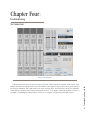
Chapter Four: Troubleshooting . . . . . . . . . . . . . 18
No Connection. . . . . . . . . . . . . . . . . . . . . 18
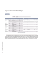
Diagnostic information with StudioEngine . . . . . . 19
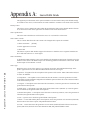
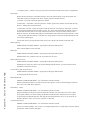
Appendix A: Source Prole Details . . . . . . . . . . .20
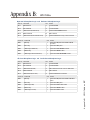
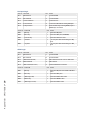
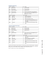
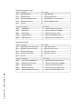
Appendix B: GPIO Tables. . . . . . . . . . . . . . . .26
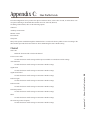
Appendix C: Show Prole Details . . . . . . . . . . . 30
Channel . . . . . . . . . . . . . . . . . . . . . . . . 30
Individual headphone section . . . . . . . . . . . 31
Record Mode . . . . . . . . . . . . . . . . . . . .32
Auxillary send & return . . . . . . . . . . . . . . . . 32
Monitor section . . . . . . . . . . . . . . . . . . . .32
Sources for External 1 & 2 . . . . . . . . . . . . 33
Control Room Monitor Options . . . . . . . . . . 33
Control Room Headphone Options . . . . . . . . 33
Studio Monitor Options . . . . . . . . . . . . . . 34
Record mode. . . . . . . . . . . . . . . . . . . . . . 34
Group start . . . . . . . . . . . . . . . . . . . . . . . 34
Appendix D: StudioEngine. . . . . . . . . . . . . . . .36
Fader Channels . . . . . . . . . . . . . . . . . . . .36
Return and monitor output. . . . . . . . . . . . . . . 36
Program and Monitor Output . . . . . . . . . . . . . 36
V-Mixer and V-Mode . . . . . . . . . . . . . . . . .37
Stream statistics . . . . . . . . . . . . . . . . . . . . 38
Options . . . . . . . . . . . . . . . . . . . . . . . .38
Network . . . . . . . . . . . . . . . . . . . . . . . . 38
System . . . . . . . . . . . . . . . . . . . . . . . . . 39
Diagnostics . . . . . . . . . . . . . . . . . . . . . .39
Appendix E: Warranty . . . . . . . . . . . . . . . . . .40
Table of Contents


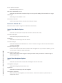
Creating the Most Exciting and Engaging
Audio Experiences Imaginable
Congratulations on your new Telos Alliance product!
The gang here at Telos is committed to shaping the future of audio by delivering innovative, intuitive
solutions that inspire our customers to create the most exciting and engaging audio experiences imaginable.
We’re grateful that you have chosen audio tools from Telos® Systems, Omnia® Audio, Axia® Audio,
Linear Acoustic®, 25-Seven Systems®, and Minnetonka Audio®. We’re here to help you make your work
truly shine. We hope that you enjoy your Telos Alliance product for many years to come and won’t hesitate
to let us know if we can help in any way.
The Telos Alliance


1: What is SoftSurface? • 1
Chapter One:
What is SoftSurface?
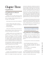
Introduction
Axia SoftSurface is a Windows application that can
be used in either of two ways:
1) As a remote control for an Axia Element control
surface, or
2) As a stand-alone mixing surface controlling an
Axia StudioEngine.
SoftSurface software requires a monitor with a
minimum resolution of 1280x1024. It can function on
Windows XP and Windows 7, 32-bit or 64-bit versions.
SoftSurface provides channel controls similar to an Axia
Element surface.
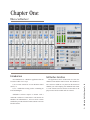
SoftSurface Interface
The application can be divided into two areas: the
channel section and the control section. The channel sec-
tion’s onscreen width can vary based on the amount of
channels you wish to display; the minimum fader count
is 4. The control section is xed in size and what is dis-
played varies based on which tabs are selected.
SoftSuface

1: What is SoftSurface? • 2
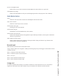
Channel Section
Figure 1-1: Onscreen faders
The number of faders displayed is dened by the
“Faders visible” option in the control section. If the num-
ber of visible faders is less than the active faders, the
scroll bar and Left/Right arrow buttons under the chan-
nel section allows the user to access those other faders by
scrolling left or right. The scroll bar has numbers on it to
indicate which ranges of faders are displayed.
Figure 1-2: Channel controls
The OFF button indicates an OFF state when “il-
luminated” orange. Pressing the button will engage the
OFF state.
The ON button indicates an ON state when “illumi-
nated” red. Pressing the button will engage the ON state.
If the source loaded to the channel has Fader Start en-
abled, the ON and OFF states are controlled by the fader
position. The ON button will only engage the ON state if
the fader is above the bottom position.
The TALK button will “illuminate” blue when
pressed and the appropriate source is loaded to the chan-
nel. The TALK function is an IFB (interrupted feedback),
also known as Talkback, and opens an audio channel
from the operator microphone to the dedicated return
audio for the source.
The Preview (PRVW) button illuminates blue when
the channel is in the preview mix (also known as a cue
mix). Pressing the button assigns the channel to the mix.
NOTE: mouse left click is a momentary press of the
button when the pointer is over the button. A mouse
right click is a press and hold of the button which the
pointer was resting above.
Figure 1-3: Fader control
The fader controls the audio gain of the source load-
ed to the channel. If the prole loaded to the channel has
Fader Start enabled, the channel automatically turns ON
when the fader is raised from its lowest position. Once
the fader is in the ON state, the ON and OFF buttons
may be used to control it. Fader in the lowest position is
always OFF state for the channel.

1: What is SoftSurface? • 3
Figure 1-4: Bus assignment buttons
Above the fader are four mix channel buttons and an
option button. The mix channel buttons represent Pro-
gram buses 1, 2, 3 and 4 and are represented with the
same number on the button. For example, will be
“illuminated” blue when the channel is feed- ing the
Program 1 mix.
The OPTION button opens other functions that can
be applied to the channel. These functions are found in
the Control section of the application. The Source Select
function is one option that is available; it allows the user
to load an audio source to the channel. When a source
is loaded, the name of that source will appear above the
channel. The top area of the channel shows the channel
number in the top left, the source name, and may also
show a status indication above or below the name based
on some state operation.
Examples of these additional displays:
Figure 1-5: Channel status displays
“Source Waiting” indicates that a source is waiting for
Channel-1 to turn OFF before loading.
The blue “X” on Channel-2 indicates that the source
is loaded but in “Listen Only” mode. This means that
some other control surface has ownership of the source
(or that there is a possible error in source ownership ad-
vertisement information).
The blue “O” on Channel-3 indicates that this is the
Operator mic channel, and that this channel is the source
audio in Talkback being sent to another destination. The
destination is indicated by a…
Blue “T” on Channel-4, which indicates that this
channel is the receiving end of talkback audio.
Control section
Figure 1-6: Assigning a source
When the Option button is pressed on a channel, the
top half of the control section will change to display the
channel source select options. The 6 icons represent dif-
ferent options that are available for a channel.
Source select allows the user to load a source to a
fader. First column shows the name of the source, 2nd
column shows the type of source, the 3rd column shows
the Livewire system name given to the source, and the
4th column shows ownership information of the source.
Highlighting a source and pressing the select button will
load the source to a channel.

1: What is SoftSurface? • 4
Feed to Source is the unique mix-minus that has been
generated for the source. This mix-minus (backfeed) can
be changed from the SoftSurface control interface. This
option is only valid for phone or codec sources.
Equalizer provides the ability to modify the fre-
quency response. This is three bands with adjustable
center frequencies.
Microphone processing provides the option to add/
adjust a noise gate, a compressor, and a de-esser. This
option is only valid for microphone, phone, or codec
sources.
Pan option provides the ability to adjust the stereo
presence of a source between the Left and Right chan-
nels. Also provided is a mode control and inverse polar-
ity. The mode function allows the user to select the ste-
reo channels from the source or one channel and create
a dual mono source.
Aux send option allows sending a channel’s output
to any of 4 auxiliary mix buses, beyond the 4 program
mixes. The control provides gain adjustment and pre- or
post-channel fader conguration.
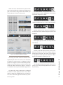
Figure 1-7: Options screens
Those are the options available through the Chan-
nel Options button. While the Option function is
enabled, there are condence meters present in the top
right corner which show presence of audio levels from
the source (and returning to the source, if the appropriate
source type is selected).
Figure 1-8: Meters, clock and timer section

1: What is SoftSurface? • 5
When none of the channels have the Options button
selected, the top half of the control section displays Pro-
gram 1 and 2 meters, along with the time and date (pro-
vided by the host PC) and a count up timer.
Figure 1-9: Connecting to Element or Engine
On startup, the control section will default to show-
ing the Setup tab in the lower section, if no connections
are dened or no auto-connect is congured. If the ap-
plication is congured to connect automatically, then the
default view will have the lower section set to the main
monitor tab. (More about this in Chapter 2, which cov-
ers installation and setup of the SoftSurface application.)
The Setup tab is where connections are congured,
the number of faders displayed on the screen, and an
option to change the conguration port is presented, in
cases where some other application installed on your PC
also uses port 80.
The Main Monitor view provides control of the
monitor speakers, operator headphones, external moni-
tor speakers, and preview volume.
Show Proles tab shows the proles that have been
congured and allow the user to select a show and load it.
Monitor options provide control over dimming val-
ues and control of the channel feeding the monitors and
headphone.
Meter options provide control over the presentation
of the meters.
Auxiliary Send and Return provides control of the
nal AUX send mix as well as two auxiliary returns as
dened in the Show Prole. The returns can be assigned
to a program bus. These options are dened in a Show
Prole and controlled as needed by the user.
The Headphone (HP) processing tab shows the fre-
quency curve of the processing and allows for control of
the processing.

1: What is SoftSurface? • 6
At the bottom of the control section is a status lamp
and two functional buttons. The status lamp provides in-
dication on the preview to operator headphone option.
There are three options: OFF, SPLIT, and STEREO.
There is a Talk to Monitor 2 button which, when en-
gaged, routes the operator microphone to the Monitor 2
source allowing communication with anyone monitor-
ing that source.
A Show Prole may have a Record Mode option en-
abled. If enabled, this button is used to enter and exit the
record mode.
Below this is the Show Prole status information,
which indicates the name of the Show loaded to the sur-
face.

2: Installation and Setup • 7
Chapter Two:
Installation and Setup
SoftSurface can be installed on Windows machines
with a minimum monitor resolution of 1280x1024. The
computer needs a static IP address within the network
scheme of the Axia LAN. If you are not clear on the IP
address to use, please contact your network administra-
tor. If you are the administrator, please call Axia support
if you need help resolving this issue. The computer also
needs a network connection to the Axia LAN.
If you will be using SoftSurface to remote-control
an Axia Element, the PowerStation paired with that Ele-
ment needs to be version 1.1.3 or higher; if your Element
is paired with a StudioEngine and Element Power Sup-
ply /GPIO, the PS/GPIO needs to be version 2.5-series
or higher. If you are using SoftSurface in stand-alone
mode, you will need an Axia StudioEngine, version
2.5.4e or higher.
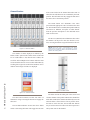
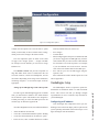
System Requirements
Windows XP or later
Video Resolution 1280x1024
Static IP
PowerStation 1.1.3 (or higher)
Element PS/GPIO 2.5 (or higher)
StudioEngine 2.5.4e (or higher)
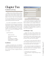
Installation
Navigate to and double click on the SoftSurface
Windows Installer Package and follow any on-screen in-
structions. A status bar will indicate the process comple-
tion. If the process appears to be stuck three quarters of
the way, check to see if there is a Register window hid-
den from view.
Figure 2-1: Registration screen
Enter the values requested. Once completed, the sta-
tus bar’s progress will continue and installation of Soft-
Surface is nished. If you’re using the SoftSurface as a
remote control for an Element, make sure the Element
is already congured and proceed to SoftSurface Setup
(next page) for setup of the SoftSurface. If you plan to
use SoftSurface in stand-alone mode, you need to con-
gure the Axia StudioEngine.
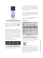
StudioEngine setup
Connect power and a network connection to the
StudioEngine. The network connection needs to come
from an approved network managed switch (see www.
AxiaAudio.com/switches/) with the appropriate congu-
ration. If assistance is needed with the conguration of
the network switch, please contact Axia support.
Also required is an Axia Audio Node which pro-
vides audio input and output and network sync source. If
you’re not familiar with Axia audio nodes, please refer
to the documentation that comes with the product.
After power has been applied, the StudioEngine will
boot; once completed you will use the front display and
rotary knob to give the device an IP address. This will
prompt the device to reboot when done.
• Press the knob (it acts as a button too)
• Rotate the knob until “4. Engine IP settings” is high-
lighted
• Press the knob to select

2: Installation and Setup • 8
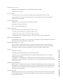
• Rotate the knob to highlight the “Net Addr” eld
• Press the knob to select
• Rotate the knob to move the cursor. Press the knob
to highlight the character under the cursor. While
highlighted, you can rotate the knob to edit the value.
Press the knob when the desired value is shown. Con-
tinue this process until the desired IP value is shown.
When done, select the check mark to exit editing.
• Adjust the net mask if required for your network.
255.255.255.0 is likely a suitable netmask value in
most installations.
• Adjust the gateway if required for your network. You
may leave this blank.
• When the IP values have been entered, select the
[OK]
If a change was made, the system should ask for a
reboot, conrm for reboot. If not, you may select “6.
System” to select a restart option.
Now, open a web browser with access to the Axia
LAN and type the IP address of your StudioEngine.
The rst order of business is to make sure the Pro-
gram and Monitor channels have unique numbers in
your network. These numbers equate to audio streams
within your network. If another device is generating a
network stream with the same number, this will cause
problems with your audio.
Select the Program and Monitor link. Authentica-
tion is requested; the default username is user with no
password.
Review the channel numbers and change as needed.
Note that all StudioEngines come with the same de-
fault numbers. For this reason it is suggested that you
change these numbers if you plan to add additional
StudioEngines to the network.
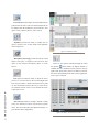
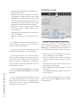
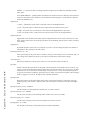
SoftSurface Setup
Figure 2-2: Specifying a connection
SoftSurface offers the ability to connect to an Ele-
ment for remote control, or to assume dedicated con-
trol of a standalone StudioEngine. If connecting to a
StudioEngine, you will need to dene the number of fad-
ers to be enabled with the “Engine fader count” setting.
• Select the device you are connecting to. Select “Ele-
ment” if connecting to a PowerStation.
• Move the computer mouse over the “IP Address”
text box to type the IP address of the device you will
control.
• Move the mouse over the “Name” text box to give a
logical name to the connection.
• Press the Add button to add the settings to your con-
nection list.
• Use the Connect button to establish a connection to
the desired device.
You can also use the Save button to save changes
made to a previous item, or Delete to remove a congu-
ration from the list.

2: Installation and Setup • 9
The Faders Visible control is used to dene the
width of the SoftSurface displayed onscreen. After set-
ting a value and pressing the Apply button, you need to
close and restart the application.
Use the Connect Automatically option to connect to
a device when the application starts without user input.
A web server port setting is available if you need to
change the port to access the application conguration
HTML interface. In most cases port 80 is suitable. If
there is another application using port 80, this option al-
lows you to change the SoftSurface port.
When using SoftSurface to remote-control single or
multiple installed Element control surfaces, dene and
save the settings in the setup section for quick access to
those devices. Select the radio button for Element under
“Connect To” and add the IP address of your Element-PS/
GPIO device(s) and/or PowerStation(s) into the connec-
tion list. Once added, select the device in the connec-
tion list and press Connect. More information on remote
control is found in Chapter 3.
Using SoftSurface in stand-alone mode is an easy
way to save on countertop space in a small production
suite or voice over booth. Select the Engine radio button
under “Connect To”, select the amount of Engine faders,
and type in the IP address of a dedicated StudioEngine.
Press the Add button and consider selecting the Auto-
matic Connection option to immediately setup the con-
nection when the application starts. Chapter 3 covers
topics for stand-alone mode.


3: Using SoftSurface • 11
Chapter Three:
Using SoftSurface
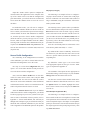
Using SoftSurface for Element
remote control
SoftSurface can act as a remote control to an existing
Element surface. This requires either PowerStation ver-
sion 1.1.3 (or higher) or Element-PS/GPIO version 2.5.0
(or higher) with a StudioEngine.
In the setup tab of the control section of SoftSurface,
• Select the “Element” option under “Connect To:”
• Enter the IP address of either the PowerStation or
Element-PS/GPIO
• Press the Connect button
You may also consider entering in a name and press-
ing the Add button to enter the connection into your con-
nection list which appears in the Setup section.
SoftSurface provides access to the channels in the
Element surface as well the monitoring section. The
functions you would have at the channel are available
remotely on the SoftSurface. The user of the SoftSur-
face may turn channels ON and OFF, adjust the gain
of a channel, change the assignment to Program mixes,
as well as adjust the channels per the Options function.
However, some Element options are not currently repre-
sented in SoftSurface; modules not available for control
via SoftSurface are the Call Control Module, Intercom
module, or SmartSwitch accessory modules.
The Element control surface will change as you
make changes in SoftSurface. As a channel is turned on
from the SoftSurface, Element’s ON lamp for the same
channel will light up.
If a fader is moved with SoftSurface, the correspond-
ing Element motorized faders will move. If motorized
faders are not installed, the Element control surface
will provide an indication in the Status area above the
fader, showing that the physical fader position does not
match the channel’s actual output value. The channel
number will be replaced with either a downward or up-
ward arrow, which indicates the direction the physical
fader must move in order to reach actual output value. If
someone were to move the physical fader at this time, no
volume change would occur until fader position matches
the value established by SoftSurface. Once the logical
and physical fader values match, the channel number re-
appears and control is given back to the physical fader.
The SoftSurface channel Options button will provide
control of the various options available to the user of the
SoftSurface, but will not change the video output of the
remote controlled Element as if the option button was
pressed. The Options buttons on the control surface and
the SoftSurface are independent of each other.
TIP: In the unlikely event of hardware failure within an
Element console, you can use SoftSurface in Stand-alone
remote control mode for the duration of time it may take
to resolve the hardware issue. Refer to the next chapter
on using the SoftSurface in stand-alone mode.
Using SoftSurface with StudioEngine
SoftSurface can act as a control surface for an Axia
StudioEngine, even if there is no hardware control sur-
face present. This requires a StudioEngine, version
2.5.4e (or higher) which is not associated with any other
Element.
In the setup tab of the control section of SoftSurface,
• Select the Engine option under “Connect To:”
• Select a value under the Engine fader count (the
amount of channels you wish this “soft” control sur-
face to have)
• Enter the IP address of the StudioEngine
• Press the Connect button
If SoftSurface will always be connecting to this En-
gine for use in Stand-alone mode, consider selecting the
“Connect Automatically” option so that when the appli-
cation starts, it connects without user input.

3: Using SoftSurface • 12
Adjust the “Faders visible” option to congure the
desired width of the application on the computer desk-
top. If the visible value is less than the congured En-
gine fader number, you will use the lower scroll bar and
arrows under the channel section to move the view of
the faders.
In Stand-alone mode, you will need to congure
Source Proles and Show Proles for the user of the sur-
face. To do this you will need to open a browser and type
in the IP address of the PC that SoftSurface is installed
on, and then proceed to Source Prole conguration.
(From the same PC you may also type 127.0.0.1 in the
browser, which is a loopback address for the PC.) When
selecting a link for the rst time, authentication may be
required. The default username and password is the
same as other Axia devices: Username: user, Password:
(no password).
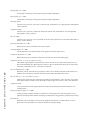
Source Prole Conguration
First connecting to the conguration user interface
of the SoftSurface, you will see various links to the left
hand side and conguration view in the center.
First step is to select the Conguration link; this
opens a view of the Show Prole list and provides ac-
cess to the Source Proles conguration.
Next, select the Source Prole link. At rst there
will be no sources shown in the center, only the Add
New Source link. You will need to dene the sources
that will be used on the SoftSurface. These denitions
will determine how the sources are treated and how the
studio will perform when the sources are used.
Select the Add New Source link. If you are familiar
with Element Source Prole conguration, you should
be able to get going on your own. If you have some ques-
tions on some of the details of Source proles, refer to
Appendix A – Source Prole Details; this will lead you
through some examples to get you started. After that you
should be able to build the remainder on your own and
refer to Appendix-A for additional options on the proles.
CD player (Line type)
The following is an example of how to congure a
CD player Source Prole. It assumes that a CD player
has been connected to an Axia Audio Node (either An-
alog or AES/EBU) using the instructions found in the
Node’s product manual.
The “Primary Source” option is where you dene the
Livewire Channel that is unique to the source. Select the
Browse button next to the text eld. A pop up will list
sources advertised on the network. Find the source for
your CD audio and select the Channel Number link. If
you do not see the desired source, it’s probably not set
up correctly; refer to the Node manual for correct setup
procedures for node sources.
Enter in a user friendly name in 10 characters or less
in the Source prole name eld, i.e.: “CD 1”.
By default all the “Source availability” check boxes
are checked. If you desire that this source not be avail-
able on a specic channel, deselect the channel’s cor-
responding box.
By default the “Source type” is set to Line which
is the appropriate option for this type of source. Other
types are explained in Appendix-A.
The remainder of the options are also appropriate in
their default setting, so the next step is to press the Save
Changes button at the bottom of the screen.
You have now created a Source Prole which can be
loaded to a channel as described in section 1-2-2. Press
the Options button of a channel, highlight the source
shown in the Control section, and press the Select but-
ton to do so.
Your Microphone (Operator Mic)
The following is an example of how to congure a
Source Prole for the user’s microphone. It assumes that
a microphone has been connected to an Axia audio node
with a microphone input or the output of a microphone
preamp is connected to an Axia audio node that accepts
the output signal from the preamp. Begin rst by click-
ing Add a new source.
Page is loading ...
Page is loading ...
Page is loading ...
Page is loading ...
Page is loading ...
Page is loading ...
Page is loading ...
Page is loading ...
Page is loading ...
Page is loading ...
Page is loading ...
Page is loading ...
Page is loading ...
Page is loading ...
Page is loading ...
Page is loading ...
Page is loading ...
Page is loading ...
Page is loading ...
Page is loading ...
Page is loading ...
Page is loading ...
Page is loading ...
Page is loading ...
Page is loading ...
Page is loading ...
Page is loading ...
Page is loading ...
Page is loading ...
Page is loading ...
-
 1
1
-
 2
2
-
 3
3
-
 4
4
-
 5
5
-
 6
6
-
 7
7
-
 8
8
-
 9
9
-
 10
10
-
 11
11
-
 12
12
-
 13
13
-
 14
14
-
 15
15
-
 16
16
-
 17
17
-
 18
18
-
 19
19
-
 20
20
-
 21
21
-
 22
22
-
 23
23
-
 24
24
-
 25
25
-
 26
26
-
 27
27
-
 28
28
-
 29
29
-
 30
30
-
 31
31
-
 32
32
-
 33
33
-
 34
34
-
 35
35
-
 36
36
-
 37
37
-
 38
38
-
 39
39
-
 40
40
-
 41
41
-
 42
42
-
 43
43
-
 44
44
-
 45
45
-
 46
46
-
 47
47
-
 48
48
-
 49
49
-
 50
50


Ask a question and I''ll find the answer in the document
Finding information in a document is now easier with AI
Related papers
-
Telos Alliance Z/IP ONE Quick start guide
-
-
-
-
Telos Alliance 11 Quick start guide
-
-
-
-
-
Other documents
-
 Axia Element Installation & User Manual
-
 Axia Fusion Installation and User Manual
-
 Telos Z/IP ONE User manual
-
 Axia Fusion Quick Start Installation Manual
-
TALLY LIGHTS 418770 User guide
-
 Axia Analog Node Owner's manual
-
 Telos NX12 User manual
-
 Telos NX12 User manual
-
Miranda EdgeVision User manual
-
Western Digital WDBACB0010HBK - Elements Play User manual


