Watts 7100643 Installation guide

Category
Sanitary ware
Type
Installation guide

This manual is also suitable for

Installation, Operation
and Maintenance Manual
Under Counter Water Filtration System
Model PWDWHCUC1
IOM-WQ-PWDWHCUC1
Table of Contents
Operational Parameters...................................3
Contents of
PWDWHCUC1 ...............................3
Tools Recommended for Installation .........................3
How To Use Quick-Connect Fittings For Tubing Connections ......3
Blue Tube Connection - Angle Stop Valve .....................4
Blue Tube Connection - Faucet Hose ........................4
System Module Mounting .................................4
System Start up.........................................4
Annual Maintenance .....................................4
Parts List / Unit Drawing ..................................5
Performance Data Sheet .................................5
Limited Warranty ........................................6
PWDWHCUC1
PURE WATER
WARNING
!
Please read carefully before proceeding with
installation. Your failure to follow any attached
instructions or operating parameters may lead to the
product’s failure.
Keep this Manual for future reference.
WARNING
!
Do not use with water that is microbiologically unsafe or of
unknown quality without adequate disinfection before or
after the system.
The PWDWHCUC1 is certied to NSF/ANSI 42 for
reduction of aesthetic chlorine, taste and odor,
NSF/ANSI 53 for the reduction of cysts, and NSF/
ANSI 372 for lead free compliance.
2
Introduction
Thank you for your purchase of a Watts water treatment
system.
Your new water treatment system contains a heavy duty
sediment, cyst and chlorine reducing filter block. The
PWDWHCUC1 water filtration provides clean, clear, great tasting
water with a higher flow and gal-lon rating than other similar
systems.
System Maintenance
Just because you cannot taste it, does not mean that it is not there.
Many contaminants in the drinking water are undetectable to the
taste. Additionally, over time if you do not replace the filter element,
other bad tastes and odors will be apparent in your drinking water.
This is why it is important to change out your filter at the recom-
mended intervals as indicated in this system manual. When replacing
the filter element, pay special attention to any cleaning instructions.
Should you have any further questions please refer to our website at
www.watts.com/purewater or call our customer service department
at 1-800-244-1299.
With proper installation and maintenance, this system will provide
you with high quality water for years to come. If you have any ques-
tions or concerns, please contact our Customer Service department
at 1-800-244-1299 or refer to our on-line troubleshooting at
www.watts.com/purewater.
Model Number:____________________Serial Number: __________________________ Date of Purchase:___________ Date of Install:______________
Installed by: ____________________________
Filter Replacement Date
If you are unsure about installing your Watts water filter, contact
a Watts representative or consult a professional plumber.
Test the water periodically to verify that the system is performing
satisfactorily. Discard small parts remaining after the installation.
Failure to install the system correctly voids the warranty.
Handle all components of the system with care. Do not drop,
drag or turn components upside down.
Be sure the floor under the water filter system is clean, level
and strong enough to support the unit.
IMPORTANT
CAUTION
!
NOTICE
3
Operating Temperatures Maximum 100°F (37.8°C) Minimum 40°F (4.4°C)
Operating Pressure
Maximum 125psi
(689 kpa)
Minimum 25psi
(172 kpa)
pH Parameters Maximum 10 Minimum 5
Flow Rate
1.6 GPM @ 60psi
Operational Parameters
Contents of Under Counter System
1 Filtration System
1 Filter - Attached
1 Parts Bag (blue tubing, brass insert, brass nut, QC stem
adapter, QC union, delrin sleeve, mounting screws)
Tools Recommended for Installation
√ Phillips bit for electric drill
√ Sharp Knife or Scisors
1/2" Adjustable
Wrench
√ Electric Drill
How to use the Quick-Connect fittings
To make a connection, the tube is simply pushed into the fitting.
Place a piece of tape
1
2" from end of tube to indicate how far the
tube should be inserted. The unique patented Quick-Connect lock-
ing system holds the tube firmly in place without deforming it or
restricting flow
Cut the tube square. It is essential that the outside diameter be free of score marks
and that burrs and sharp edges be removed before inserting into fitting.
Fitting grips before it seals. Ensure tube is pushed into the tube stop.
Push the tube into the fitting, to the tube stop. The collet (gripper) has stainless
steel teeth which hold the tube firmly in position while the O-ring provides a perma-
nent leak proof seal.
P
ull on the tube to check that it is secure. Always test the system for leaks
following installation and before use, and periodically during use.
T
o disconnect, ensure the system is depressurized before removing the tube. Push
in collet squarely against face of fitting. With the collet held in this position, the tube
can be removed. Do not reconnect. Quick-Connect fitting can be reused only on
a new connection or after existing tube ends are recut free of score marks, burrs
and damage.
Check to confirm that you have all parts. Inspect all parts for
signs of damage, cracks, kinks, wear or breaks. DO NOT USE if
damages in any way. Contact If any of the items are missing
please contact Watts Customer Service for replacement parts.
System is intended to be installed on the cold water line
ONLY. Do not use with hot water supply.
• Do not install if your water lines are susceptible to water
hammer.
• System to be used with municipal or well water sources
properly treated and tested on regular basis to insure
suitable and non-adverse water conditions, including
bacteriological safe quality.
4
Blue Tube Connection- Angle Stop Valve
Do not use with hot water supply. Hot water will severely
damage your system, will not filter properly, and can result in
leaks and property damage. Water supply line to the system
must be from the cold water supply only.
Step A - Turn off the cold water
supply to the faucet by
turning the angle stop
valve completely off.
Step B - Open cold water sink
faucet to relieve pressure.
Step C - Place a small container
under the cold water
angle stop valve to catch
any runoff water. Discon-
nect the cold water faucet
supply hose from the cold
water angle stop valve.
Step D - Locate the blue 3/8” tube
in the parts bag. Remove
a brass nut, plastic delrin
sleeve and brass insert
from the parts bag. To
assemble, place the brass
nut on the blue tube first
(Open end out), then the
sleeve and then push
the brass insert all the way into the end of the tube. (See
Picture).
Step E - Insert the assembled blue tube into the open fitting of the
cold water angle stop valve and simply tighten using an
adjustable wrench. DO NOT OVER TIGHTEN.
STEP 1
Blue Tube Connection- Faucet Hose
Step A - Locate the threaded 3/8” male stem
adapter fitting in the parts bag. Thread the stem
adapter on to the supply hose attached to the
faucet and tighten with an adjust-able wrench.
Step B - Locate the 3/8”x3/8” Quick Connect
union in the parts bag. Push the union on to the
3/8” stem adapter fitting attached to the faucet hose
until fully seated.
Step C - Connect the open end of the 3/8” blue
tube to the open end of the 3/8”x3/8” Quick con-
nect union fitting by pushing the tube into the
adapter until fully seated.
STEP 2
STEP 3
System Module Mounting
- Wood Surface
Step A – Determine best location for
the filtration system to be mounted
and spliced into the 3/8” blue tubing.
Using the mounting holes on the
bracket, mark the location for the
mounting screws on the cabinet wall
under the sink (Make sure to leave
enough room to remove the filter during
STEP 4
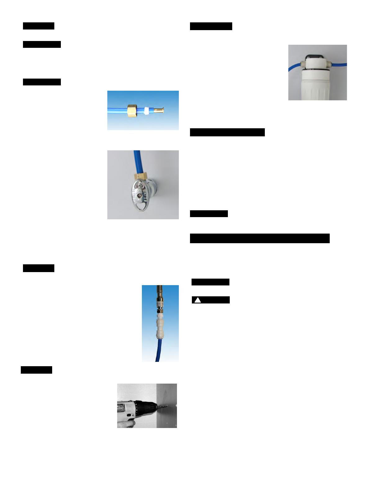
Blue Tube Connection - Filtration System
Step A - After mounting the system,
determine where and cut the
3/8” blue tubing into two parts
in order to connect it to the
filtration system.
Step B - Connect the 3/8” blue tube
coming from the angle stop
valve into the left side of the
filtration system (IN), by pushing
the tubing firmly into the quick
connect fitting. Connect the
3/8” blue tube coming from the faucet supply hose into
the right side of the filtration system (OUT), by pushing the
tubing firmly into the quick connect fitting.
System Start Up
Step A– Slowly turn on water. Check for signs of leaks or damage at all
locations including water supply connection, at cold water faucet hose
connection, at quick connect fittings, at angle stop valve connection and at
filter module and cartridges. Inspect connections, lines and filter module/
cartridges at least every six months thereafter for signs of leaks or damage.
Turn water off immediately and replace if leaking, weeping, cracked, damaged
or corroded.
Step B – Run 5 gallons of water through the unit in order to flush out the
normal black carbon fines (it will “sputter” until the air is purged out) from the
unit. Initially, the water may appear cloudy which is due to tiny air bubbles and
it will clear up shortly. Close the faucet when finished.
Check frequently over the next 24 hours to ensure no leaks are present
NOTICE
NOTICE
NOTICE
Maintenance
Ordering Code: EDP# 7100643 Includes: (1) Carbon Block Cyst Filter
NOTICE At least every 12 months, you must change the filter with a
new Watts filter.
Step B – Open the cold water faucet handle to relieve the water pressure
Step C – Remove filter from lid by turning it to the left, then pull-
ing the filter down out of the lid. Properly dispose of old filter.
Do not reuse. Cannot be recycled.
Step D – Remove plastic wrapping and cap from new filter.
Step E – To install new filter cartridge, with the filter label facing
approximately 45 degrees to the left, push the filter
into the lid and hand twist it to the right until the filter
locks in and the label on filter is facing the front.
Step F – Follow System Start Up procedure.
filter changes, approximately 2” below filter). In the parts bag, locate
the two self tapping screws. Using an electric drill with a Phillips bit,
screw them into the cabinet at the marked location. Hang the system
on the screws using the mounting holes in the bracket
Annual Filter Change Out
Step A – Turn off incoming water supply to the filtration unit.
NOTICE
!
WARNING
No one who has a compromised or weak immune system
should change filters due to possible exposure to germs and bacteria.
Always wear gloves and thoroughly wash hands immediately after changing
filter.
Routine Maintenance
Step A - Regularly check for any leaks or damaged parts or connections.
Step B
- Make sure system installation has adequate clearance at all
times with nothing touching filter, tubes or connections.
Step C - Regularly test water supply and output to confirm water
condition and filter performance.
5
Parts List
IteM # OrderIng cOde descrIPtIOn
1
7300767
3/8" Brass Insert (not shown)
2
7300768
3/8" Delrin Sleeve (not shown)
3
7300769
3/8" Brass Nut
4
7300067
3/8" Blue Tubing
5
7300770
3/8" QC Union
6
7300771
3/8" QC Stem Adapter
7
7300766
System Head Assembly
8
7100643
15" HC Carbon Filter
Under Counter System
5
3
6
4
7
8
2
1
To Loosen To Tighten
WATTS
8716 W Ludlow Drive Suite #1
Peoria, AZ 85381
PWDWHCUC1
GENERAL USE CONDITIONS:
1: System to be used with municipal or well water sources treated and tested on regular basis to insure bacteriological safe quality. DO NOT
use with water that is micro biologically unsafe or of unknown quality without adequate disinfection before or after the system. Systems certified
for cyst reduction may be used on disinfected waters that may contain filterable cysts.
2: Operating Temperature: Maximum 100
o
F (38
o
C) Minimum 40
o
F (4.4
o
C)
3: Operating Water Pressure: Minimum 25-psi (172kpa)
4: Maximum flow Rate:
5: Rated Capacity (Chlorine):
Maximum 125
-psi (689kpa)
1.6 gpm (6.06 lpm)
10000 Gallons (37,854 liters)
RECOMMENDED REPLACEMENT PARTS AND CHANGE INTERVAL:
Depending on incoming feed water conditions
replacement time frame may vary.
Description Part Number Change time Frame
PWCBHCUC1 7100643 10000 gallons of water
Performance Data Sheet
The PWDWHCUC1 is certied to NSF/ANSI 42 for
reduction of aesthetic chlorine, taste and odor,
NSF/ANSI 53 for the reduction of cysts, and NSF/
ANSI 372 for lead free compliance.
WARNING
!
The PWDWHCUC1 system has been tested according to NSF/ANSI 42, 53, for reduction of the substances listed below. The concentration of
the indicated substances in water entering the system was reduced to a concentration less than or equal to the permissible limit for water
leaving the system, as specied in NSF/ANSI 42.
While testing was performed under standard laboratory conditions, actual performance may vary.
Testing parameters: Flow rate 1.6 gpm pH 7.6 gpm Water pressure: 60 psi.
Cyst Reduction Flow Reduction Influent Effluent 1 Effluent 2
Influent Avg. 370000 count/L Eighth Cycle 130000 <25 <25
Effluent Avg. <25 count/L 25% 210000 <25 <25
Percent Reduction >99.98 % 50% 333000 <25 <25
Maximum Effluent <25 count/L 75% 810000 <25 <25
IOM-WQ-
PWDWHCUC1 1551 299803 © 2015 Watts
USA: Tel. (800) 224-1299 www.Watts.com/PureWater
Canada: Tel. (888) 208-8927 www.Watts.ca/PureWater
A Watts Water Technologies Company
LIMITED WARRANTY: Cer tain Watts Pure Water products come with a limited warranty from Watts Regulator Co. O ther products may have no warranty or are covered by the original manufacturer’s
warranty only. For specic product warranty information, please visit www.watts.com or the published literature that comes with your product. Any remedies stated in such war-
ranties are exclusive and are the only remedies for breach of warranty. EXCEPT FOR THE APPLICABLE PRODUCT WARRANTY, IF ANY, WATTS MAKES NO OTHER WARRANTIES, EXPRESS OR
IMPLIED. TO THE FULLEST EXTENT PERMITTED BY APPLICABLE LAW, WATTS HEREBY SPECIFICALLY DISCLAIMS ALL OTHER WARRANTIES, EXPRESS OR IMPLIED, INCLUDING BUT NOT LIMITED
TO THE IMPLIED WARRANTIES OF MERCHANTABILITY AND FITNESS FOR A PARTICULAR PURPOSE, AND IN NO EVENT SHALL WATTS BE LIABLE, IN CONTRACT, TORT, STRICT LIABILITY OR UNDER
ANY OTHER LEGAL THEORY, FOR INCIDENTAL, INDIRECT, SPECIAL OR CONSEQUENTIAL DAMAGES, INCLUDING, WITHOUT LIMITATION, LOST PROFITS OR PROPERTY DAMAGE, REGARDLESS OF
WHETHER IT WAS INFORMED ABOUT THE POSSIBILITY OF SUCH DAMAGES.
WARNING: This product contains chemicals known
to the State of California to cause cancer and birth
defects or other reproductive harm.
For more information: www.watts.com/prop65
  • Page 1 1
  • Page 2 2
  • Page 3 3
  • Page 4 4
  • Page 5 5
  • Page 6 6

Watts 7100643 Installation guide

Category
Sanitary ware
Type
Installation guide
This manual is also suitable for

Ask a question and I''ll find the answer in the document

Finding information in a document is now easier with AI