Watts PWMB10M5 Installation guide

Type
Installation guide

This manual is also suitable for

IOM-WQ-PWDWLCV2
PWDWLCV2
Installation, Operation
and Maintenance Manual
2-Stage LCV Under Counter System
Model PWDWLCV2
Table of Contents
Maintenance Record . . . . . . . . . . . . . . . . . . . . . . . . . . . . . . . . . . . . . 2
Operational Parameters. . . . . . . . . . . . . . . . . . . . . . . . . . . . . . . . . . . 3
Contents of LCV System . . . . . . . . . . . . . . . . . . . . . . . . . . . . . . . . . . 3
Tools Recommended For Installation . . . . . . . . . . . . . . . . . . . . . . . . 3
Drill / Punch a Hole for Watts Top Mount Faucet . . . . . . . . . . . . . . . . 3
Standard Faucet Installation. . . . . . . . . . . . . . . . . . . . . . . . . . . . . . . . 4
Drinking Water Module Mounting. . . . . . . . . . . . . . . . . . . . . . . . . . . . 5
Adapt-A-Valve™ Installation . . . . . . . . . . . . . . . . . . . . . . . . . . . . . . . 5
Start Up. . . . . . . . . . . . . . . . . . . . . . . . . . . . . . . . . . . . . . . . . . . . . . . 5
Filter Change . . . . . . . . . . . . . . . . . . . . . . . . . . . . . . . . . . . . . . . . . . . 6
Parts Listing . . . . . . . . . . . . . . . . . . . . . . . . . . . . . . . . . . . . . . . . . . . 7
Performance Data Sheet . . . . . . . . . . . . . . . . . . . . . . . . . . . . . . . 8-9
Limited Warranty . . . . . . . . . . . . . . . . . . . . . . . . . . . . . . . . . . . . . . . 12
WARNING
!
Please read carefully before proceeding with
installation. Your failure to follow any attached
instructions or operating parameters may lead to the
product’s failure.
Keep this Manual for future reference.
PENSER
SÉCURITÉ
AVANT
TOUT
WARNING
!
Do not use with water that is microbiologically unsafe or of
unknown quality without adequate disinfection before or
after the system.
If you are unsure about installing your WATTS water filter, contact
a WATTS representative or consult a professional plumber.
Test the water periodically to verify that the system is performing
satisfactorily.
Discard small parts remaining after the installation.
Failure to install the system correctly voids the warranty.
Handle all components of the system with care. Do not drop,
drag or turn components upside down.
Be sure the floor under the water filter system is clean, level
and strong enough to support the unit.
IMPORTANT
CAUTION
!
NOTICE
System tested and certifi ed by WQA against
NSF/ANSI Standard 53 for the reduction of the
claims specifi ed on the performance data sheet
and NSF/ANSI Standard 372 for lead free.
Watts Pure Water
8716 W Ludlow Drive Suite #1, Peoria, AZ 85381, 1-(800)-224-1299
2
Thank you for your purchase of a
state of the art Watts Pure Water
Treatment system.
PWDWLCV2 Water Treatment System:
Watts Pure Water PWDWLCV2 water treatment system contains a
heavy duty lead, cyst and VOC filter block. This specialty formulated
block is capable of reducing lead, cryptosporidium, Giardia, Ent-
amoeba as well as harmful Volatile Organic Chemicals. It is estimated
that VOC’s are present in one-fifth of the nation’s water supplies.
These water contaminants can enter ground water from a variety of
sources including localized use of herbicides and pesticides, gasoline
or oil spills, leaking underground fuel tanks, septic system cleaners,
and chemicals used in the dry-cleaning industry.
System Maintenance
Just because you can not taste it, does not mean that it is not there.
Many contaminants in the drinking water are undetectable to the
taste. Additionally, over time if you do not replace the filter element,
other bad tastes and odors will be apparent in your drinking water.
This is why it is important to change out your filter at the recom-
mended intervals as indicated in this system manual. When replac-
ing any of the filter elements, pay special attention to any cleaning
instructions. Should you have any further questions please refer to
our website at www.watts.com/purewater or call our customer
service department at 1-800-244-1299.
Maintenance Record
This system has been designed to fit under most kitchen sinks.
Please read carefully before proceeding with installation.
DATE OF PURCHASE DATE OF INSTALL INSTALLED BY
Notes:
NOTICE
Operational Parameters
Installation needs to comply with state and local plumbing regula-
tions. This system is intended to be installed on the cold supply line
only.
Contents of Under Counter System
1 LCV Unit
2 Filters
1 Parts Bag
1 Faucet Assembly
If any of the items are missing, please contact Watts prior to install-
ing.
Tools Recommended For Installation
A small knife
Variable speed drill
1
8" (3mm),
1
4" (6.4 mm) and
7
16" (11.0mm) drill bits
1
1
4" hole saw (for porcelain sinks) or 1
1
4" hole punch (for stainless
steel sinks)
1
2" and
5
8" open-end wrenches (or adjustable wrenches)
Phillips screwdriver
3
MAXIMUM MINIMUM
Operational Temperature 100°F (37.8°C) 40°F (4.4°C)
Operating Pressure 85psi (5.98 kg/cm²) 20psi (1.406 kg/cm²)
pH Parameters 10 5
Flow Rate 0.5 GPM @ 60 psig
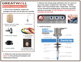
Drill a Hole for the Faucet in a Porcelain Sink
Most sinks are predrilled with 1½" or 1¼" diameter hole that
you can use for your RO faucet. (if you are already using it for a
sprayer or soap dispenser, see Step 2).
Porcelain sinks are extremely hard and can crack or chip easily.
Use extreme caution when drilling. Watts accepts no responsi-
bility for damage resulting from the installation of faucet.
Step A – Determine desired location for
the RO faucet on your sink
and place a piece of masking
tape on over where the hole is
to be drilled. Mark the center
of the hole on the tape.
Step B – Using a variable speed drill
set on the slowest speed, drill
a
1
8“ pilot hole through both
porcelain and metal casing
of sink at the marked center
of the desired location. Use
lubricating oil or liquid soap
to keep the drill bit cool (If drill
bit gets hot it may cause the
porcelain to crack or chip).
Step C – Using a 1¼" hole saw, pro-
ceed to drill the large hole.
Keep drill speed on the slow-
est speed and use lubricating
oil or liquid soap to keep the
hole saw cool during cutting.
Step D – Make sure the surroundings
of the sink are cooled before
mounting the faucet to the
sink after drilling and remove
all sharp edges.
STEP 1
Punch a Hole for the Faucet in a Stainless
Steel Sink
If mounting faucet to a Stainless Steel
Sink you will need a 1¼" Hole Punch.
The faucet opening should be centered
between the back splash and the edge
of the sink, ideally on the same side as
the vertical drain pipe.
Step A – Drill a ¼" pilot hole. Use a
1
2"
Hole Punch and an adjustable
wrench to punch the hole in the
sink. Change to the 1¼" Hole
Punch to enlarge the hole
The faucet can now be installed.
OR
NOTICE
NOTICE
NOTICE
4
STEP 2
Step a – Under the sink - on to the threaded faucet stem in order
first slide on the plastic spacer (Item 7), the washer (Item
8), the slotted washer (Item 9), and lastly secure with nut
(Item 10).
Step D – Locate the blue 1/4” tube in the faucet parts bag. Remove
a brass nut (Item 13), plastic sleeve (Item 12) and insert
(Item 11) from the parts bag. To assemble, place the brass
nut on the blue tube first, then the sleeve (small tapered
end of sleeve must point to the end of tube) and then push
the insert all the way into the end of the tube.
Step E – Insert the blue tube into the end of the faucet shank and
use a wrench to tighten the brass nut securely.
DO NOT overtighten nut.
4
5
6
7
8
9
10
11
13
12
3
1
2
NOTICE
5
STEP 3
Drinking Water Module Mounting
Step A – Determine best location for
the Drinking Water system to
be mounted to allow for future
system maintenance. The
parts bag has 2 self tapping
screws. Using an electric drill
with a Phillips bit, screw them
into the cabinet wall 6" apart
and 16" from the bottom of the
cabinet.
Do not cut any Drinking Water system tubes at this time
Start Up Instructions
Step A– Turn on the incoming cold water at the angle stop valve.
Turn the knob on the Adapt-A-Valve™ by turning coun-
terclockwise. Check the system for leaks and tighten any
fittings as necessary. (Check frequently over the next 24
hours to ensure no leaks are present).
If you have connected your RO system to a refrigerator / ice
maker, make sure the ice maker is off (do not allow water to flow
to the ice maker) until flushing is complete and the tank has
been allowed to fill completely. Connection from the RO to the
ice maker system should have an in-line valve installed before
the ice maker so it can easily be closed to prevent water flowing
to the ice maker during start up and periodic maintenance. Your
RO tank must be allowed to fill up fully in order for the ice maker
system to work properly.
Step B – Turn faucet handle to the open position to start the flow
of water through the unit. Run 7 gallons of water through
the unit in order to flush out the normal black carbon fines
(it will “sputter” until the air is purged out) from the unit.
Initially, the water may appear cloudy which is due to tiny
air bubbles and it will clear up shortly. Close the faucet.
Step C – Check for leaks. If you have any leaks, shut off the water
supply to your system, repair and restart unit.
Adapt-A-Valve™ Installation
Verify contents prior to installation:
( 1 ) - Plastic Adapt-a-Valve™ & Black Collet
( 1 ) - Brass Adapter no washer
( 1 ) - Brass Adapter with black washer
( 1 ) - White rubber washer
Water supply line to the system must be from the cold water
supply line only. Hot water will severely damage your system.
Do not use Teflon tape with the Adapt-A-Valve™.
For
3
8" Configuration
For
1
2" Configuration
Step A - Turn off the cold water supply to the faucet by turning the
angle stop valve completely off.
Step B - Open cold water sink faucet to relieve pressure.
Step C - Choosing the configuration that fits your plumbing, at-
tach the Adapt-A-Valve™ as illustrated in the four photos
above.
STEP 4
Hot
Supply
Cold
Supply
Hot
Supply
Cold
Supply
(With Brass Fittings)
* Insert White Washer
(Without Brass Fittings)
1
2" Configuration
NOTICE
NOTICE
6
Filter Change
Order filter by calling Watts at 1-800-224-1299
Watts recommends changing the filter element every 6 months.
Use Watts replacement cartridge only. Other filters may look the
same, but only filters by Watts are manufactured to fit your LCV filter
unit in order to ensure proper reduction of water contaminants.
A. Turn off incoming water supply to the LCV unit by turning the
KNOB on the Adapt-A-Valve™ clockwise. Note: There will be
water in the filter housing. Lift the faucet handle to relieve the
water pressure.
B. Remove filter housing from lid by turning it to the left, as shown in
Figure D.
C. Remove used filter cartridge and discard.
Do not discard filter-housing O-ring.
D. Clean inside of filter housing with warm soapy water and rinse to
remove soap
E. Lubricate O-ring with water-soluble lubricant (i.e. K-Y Jelly
®
or
Silicone lubricant).
Do not use Petroleum based lubricants such as Vaseline
®
.
F. Seat O-ring in groove in filter housing and insert new filter car-
tridges into filter housing.
G. Screw filter housing onto lid as shown in Figure D.
H. Turn on water supply to filter unit by turning knob on
Adapt-A-Valve™ counterclockwise
I. Check system for leaks.
To Loosen To Tighten
Figure D
Replacement
Filters Pack
MODEL FREQUENCY DESCRIPTION
PWFPKLCV 6 Months
PWMB10M5 (5-micron sediment filter) &
PWCB10LCV (1 micron carbon filter)
Water conditions may require more frequent cartridge replacement
NOTICE
NOTICE
NOTICE
7
ITEM EDP DESCRIPTION
1 7300068 ADAPT-A-VALVE™
2 7300031 ELBOW - 1/4" C X 1/4" M
3 7300081 FILTER HOUSING - LID - 1/4" PORTS
4 7300044 FILTER HOUSING - BOWL - 10" - WHITE
5 7300060 O-RINGS FOR FILTER HOUSING
6 7100331 SEDIMENT FILTER
7 7100451 LEAD, CYST, VOC Carbon Block
8 7100188 FAUCET - CHROME
9 7300066 1/4" GREEN TUBING
10 7300065 1/4" BLUE TUBING
Parts List
MAIN WATER SUPPLY
SHUT-OFF VALVE
CARBON
BLOCK
SEDIMENT
FILTER
1/4” GREEN TUBE
FEED WATER
STANDARD FAUCET
ADAPT-A-VALVE
1
TO
KITCHEN
SINK
2
3
4
3
4
2
8
5 5
6 7
1/4” BLUE TUBE
9
10
8
GENERAL USE CONDITIONS:
1: System to be used with municipal or well water sources treated and tested on regular basis to insure bacteriological safe quality. DO
NOT use with water that is micro biologically unsafe or of unknown quality without adequate disinfection before or after the system.
Systems certified for cyst reduction may be used on disinfected waters that may contain filterable cysts.
2: Operating Temperature: Maximum 100
o
F (37.8
o
C) Minimum 40
o
F (4.4
o
C)
3: Operating Water Pressure: Maximum 85psi (5.98 kg/cm
2
) Minimum 20psi (1.406 kg/cm²)
4: Maximum flow Rate: 0.50 gpm (1.89 lpm)
5: Rated Capacity: 600 Gallons (2,200 liters)
RECOMMENDED REPLACEMENT PARTS AND CHANGE INTERVAL:
Note: Depending on incoming feed water conditions replacement time frame may vary.
Description Part Number Change time Frame
Stage 1: Sediment filter 7100331 6 Months or 600 gallons of water
Stage 2: Lead, Cyst, VOC Carbon block 7100451 6 Months or 600 gallons of water
This system has been tested according to NSF/ANSI Standard 53 for the reduction of the substances listed below. The concentration
of the indicated substances in water entering the system was reduced to a concentration less than or equal to the permissible limit for
water leaving the system, as specified in NSF/ANSI 53. Testing performed under standard laboratory conditions, actual performance
may vary.
Substance
Percent
Reduction
Influent Challenge
Concentration
(mg/L unless noted)
Maximum Permissible
Product Water
Concentration
ALACHLOR* >98% 0.050 0.001
ATRAZINE* >97% 0.100 0.003
BENZENE* >99% 0.081 0.001
BROMODICHLOROMETHANE (TTHM)* >99.8% 0.300 +/- 0.30 0.015
BROMOFORM (TTHM)* >99.8% 0.300 +/- 0.30 0.015
CARBOFURAN (Furadan)* >99% 0.190 0.001
CARBON TETRACHLORIDE* 98% 0.078 0.0018
CHLORDANE 0.04 +/- 0.10 0.002
CHLOROBENZENE (Monochlorobenzene)* >99% 0.077 0.001
CHLOROFORM (TTHM)* >99.8% 0.300 +/- 0.30 0.015
CRYPTOSPORIDIUM (see Cyst) 99.99% minimum 50,000/mL 99.95%
CYST 99.99%
minimum 50,000/mL 99.95%
CHLOROPICRIN 0.015 0.0002
2, 4-D* 98% 0.110 0.0017
DBCP (see Dibromochloropropane)* >99% 0.052 0.00002
1,2-DCA (see 1,2-DICHLOROETHANE)* 95% 0.088 0.0048
1,1-DCE (see 1,1-DICHLOROETHYLENE)* >99% 0.083 0.001
DIBROMOCHLOROMETHANE
(TTHM;Chlorodibromomethane)*
>99.8% 0.052 0.00002
DIBROMOCHLOROPROPANE (DBCP)* >99% 0.004 +/- 0.10 0.0002
o-DICHLOROBENZENE (1,2 Dichlorobenzene)* >99% 0.080 0.001
p-DICHLOROBENZENE (para-Dichlorobenzene)* >98% 0.040 0.001
1,2-DICHLOROETHANE (1,2-DCA)* 95% 0.088 0.0048
1,1-DICHLOROETHYLENE (1,1-DCE)* >99% 0.083 0.001
CIS-1,2-DICHLOROETHYLENE* >99% 0.170 0.0005
TRANS-1,2- DICHLOROETHYLENE* >99% 0.086 0.001
1,2-DICHLOROPROPANE (Propylene Dichloride)* >99% 0.080 0.001
CIS-1,3- DICHLOROPROPYLENE* >99% 0.079 0.001
DINOSEB* 99% 0.170 0.0002
EDB (see ETHYLENE DIBROMIDE)* >99% 0.044 0.00002
ENDRIN* 99% 0.006 +/- 0.10 0.002
Watts Pure Water
8716 W Ludlow Drive Suite #1
Peoria, AZ 85381
1-(800)-224-1299
Performance Data Sheet
PWDWLCV2
9
Substance
Percent
Reduction
Influent Challenge
Concentration
(mg/L unless noted)
Maximum Permissible
Product Water
Concentration
ENTAMOEBA 99.99%
minimum 50,000/mL 99.95%
ETHYLBENZENE* >99% 0.088 0.001
ETHYLENE DIBROMIDE (EDB)* >99% 0.044 0.00002
FURADAN (see CARBOFURAN)* >99% 0.19 0.001
HALOACETONITRILES (HAN)*
BROMOCHLOROACETONITRILE 98% 0.022 0.0005
DIBROMOACETONITRILE 98% 0.024 0.0006
DICHLOROACETONITRILE 98% 0.0096 0.0002
TRICHLOROACETONITRILE 98% 0.015 0.0003
HALOKETONES (HK):*
1,1-DICHLORO-2-PROPANONE 99% 0.0072 0.0001
1,1,1-TRICHLORO-2-PROPANONE 96% 0.0082 0.0003
GIARDIA LAMBLIA (see Cyst) 99.99%
minimum 50,000/mL 99.95%
HEPTACHLOR* >99% 0.025 0.00001
HEPTACHLOR EPOXIDE* 98% 0.0107 0.0002
HEXACHLOROBUTADIENE
(Perchlorobutadiene)*
>98% 0.044 0.001
HEXACHLOROCYCLOPENTADIENE* >99% 0.060 0.000002
LEAD pH 6.5 99% 0.15 +/- 10% 0.010
LEAD pH 8.5 99% 0.15 +/- 10% 0.010
HEPTACHLOR (H-34, HEPTOX) 0.08 +/- 0.10 0.0004
HEPTACHLOR EPOXIDE 0.004 +/- 0.10 0.0002
HEXACHLOROCYCLOPENTADI 0.15 +/- 0.10 0.05
LINDANE* >99% 0.055 0.00001
METHOXYCHLOR* >99% 0.050 0.0001
METHYLBENZENE (see TOLUENE)* >99% 0.015 +/- 0.20 0.005
MONOCHLOROBENZENE
(see CHLOROBENZENE)*
>99% 0.077 0.001
PCE (see TETRACHLOROETHYLENE)* >99% 0.081 0.001
PENTACHLOROPHENOL* >99% 0.096 0.001
PERCHLOROBUTADIENE
(see HEXACHLOROBUTADIENE)*
>98% 0.044 0.001
PROPYLENE DICHLORIDE
(see 1,2 -DICHLOROPROPANE)*
>99% 0.080 0.001
POLYCHLORINATED BIPHENYLS (PCBs, Aroclor 1260) 0.01 +/- 0.10 0.0005
SIMAZINE* >97% 0.120 0.004
SILVEX (see 2,4,5-TP)* 99% 0.270 0.0016
STYRENE (Vinylbenzene)* >99% 0.150 0.0005
1,1,1-TCA
(see 1,1,1 - TRICHLOROETHANE)*
95% 0.084 0.0046
TCE (see TRICHLOROETHYLENE)* >99% 0.180 0.0010
1,1,2,2- TETRACHLOROETHANE* >99% 0.081 0.001
TETRACHLOROETHYLENE* >99% 0.081 0.001
TOLUENE (Methylbenzene)* >99% 0.078 0.001
TOXOPLASMA
minimum 50,000/mL 99.95%
2,4,5-TP (Silvex)* 99% 0.270 0.0016
TRIBROMOACETIC ACID* 0.042 0.001
TOXAPHENE 0.015 +/- 0.10 0.003
1,2,4 TRICHLOROBENZENE (Unsymtrichlorobenzene)* >99% 0.160 0.0005
1,1,1-TRICHLOROETHANE (1,1,1-TCA)* 95% 0.084 0.0046
1,1,2-TRICHLOROETHANE* >99% 0.150 0.0005
TRICHLOROETHYLENE (TCE)* >99% 0.180 0.0010
TRIHALOMETHANES (TTHM) (Chloroform; Bromoform;
Bromodichloromethane; Dibromochloromethane)
>99.8% 0.300 0.015
Unsym-Trichlorobenzene (see 1,2,4-
TRICHLOROBENZENE)*
>99% 0.160 0.0005
Vinylbenzene (see STYRENE)* >99% 0.150 0.0005
XYLENES >99% 0.070 0.001
10
11
IOM-WQ-PWDWLCV2 1830 EDP# 7100101 © 2018 Watts
USA: T: (800) 224-1299 • F: (978) 794-1848 • Watts.com/PureWater
Canada: T: (905) 332-4090 • F: (905) 332-7068 • Watts.ca/PureWater
Latin America: T: (52) 81-1001-8600 • Watts.com/PureWater
LIMITED WARRANTY: Certain Watts Pure Water products come with a limited warranty from Watts Regulator Co. Other products may have no warranty or are covered by the original manufacturer’s
warranty only. For specific product warranty information, please visit www.watts.com or the published literature that comes with your product. Any remedies stated in such warranties are exclusive and
are the only remedies for breach of warranty. EXCEPT FOR THE APPLICABLE PRODUCT WARRANTY, IF ANY, WATTS MAKES NO OTHER WARRANTIES, EXPRESS OR IMPLIED. TO THE FULLEST EXTENT
PERMITTED BY APPLICABLE LAW, WATTS HEREBY SPECIFICALLY DISCLAIMS ALL OTHER WARRANTIES, EXPRESS OR IMPLIED, INCLUDING BUT NOT LIMITED TO THE IMPLIED WARRANTIES OF
MERCHANTABILITY AND FITNESS FOR A PARTICULAR PURPOSE, AND IN NO EVENT SHALL WATTS BE LIABLE, IN CONTRACT, TORT, STRICT LIABILITY OR UNDER ANY OTHER LEGAL THEORY, FOR
INCIDENTAL, INDIRECT, SPECIAL OR CONSEQUENTIAL DAMAGES, INCLUDING, WITHOUT LIMITATION, LOST PROFITS OR PROPERTY DAMAGE, REGARDLESS OF WHETHER IT WAS INFORMED ABOUT
THE POSSIBILITY OF SUCH DAMAGES.
  • Page 1 1
  • Page 2 2
  • Page 3 3
  • Page 4 4
  • Page 5 5
  • Page 6 6
  • Page 7 7
  • Page 8 8
  • Page 9 9
  • Page 10 10
  • Page 11 11
  • Page 12 12

Watts PWMB10M5 Installation guide

Type
Installation guide
This manual is also suitable for

Ask a question and I''ll find the answer in the document

Finding information in a document is now easier with AI