Page is loading ...

Page 1
INSTALLATION, OPERATION AND MAINTENANCE MANUAL
DELUXE PLUS
PREMIER 25
ULTRA 5
RO-TFM-4SV
RO-TFM-5SV
PUR-TEK
Refer to enclosed warranty for operating parameters to ensure proper use with your water supply.
Watts Premier, Inc. 8716 W Ludlow Drive Suite #1 Peoria, AZ 85381
Phone: 800-752-5582 www.premierH2o.com Fax: 623-866-5666
Save manual for future reference
MODELS
Warning
Please read carefully before proceeding with installation. Your failure to follow any attached instructions
or operating parameters may lead to the product’s failure.
System tested and certied by NSF International against NSF/
ANSI Standard 58 for the reduction of the claims specied on the
performance data sheet.
Manual Edition: 09/13/10
P/N 199348
EPA / ETV Test veried performance.
Physical removal of microbial
contamination agents in drinking water.

Page 2
This page has been left blank intentionally.

Page 3
Thank you for your purchase of a state of the art Watts Premier Reverse Osmosis (RO) water treatment system. Water
quality concerns are becoming more of a focus for the public. You may have heard about contaminants in the drinking water,
such as Arsenic, Chromium, Cryptosporidium or Giardia. There may also be some local water issues such as high levels of
Lead and Copper. This Watts Premier water treatment system has been designed and tested to provide you with high quality
drinking water for years to come. The following is a brief overview of the system.
Your Reverse Osmosis System:
Osmosis is the process of water passing through a semi permeable membrane in order to balance the concentration of
contaminants on each side of the membrane. A semi permeable membrane is a barrier that will pass some particles like clean
drinking water, but not other particles like arsenic and lead.
Reverse osmosis uses a semi permeable membrane; however, by applying pressure across the membrane, it concentrates
contaminants (like a strainer) on one side of the membrane, producing crystal clear water on the other. This is why RO
systems produce both clean drinking water and waste water that is ushed from the system. This reverse osmosis system also
utilizes carbon block ltration technology, and can therefore provide a higher quality drinking water than carbon ltration
systems alone.
Your system is a four or ve stage RO which is based upon separate treatment segments within the one complete water
ltration system. These stages are as follows:
Stage 1 – Sediment lter, recommended change 6 months.
The rst stage of your RO system is a ve micron sediment lter that traps sediment and other particulate matter
like dirt, silt and rust which affect the taste and appearance of your water.
Stage 2 and 3 – Carbon lters, recommended change 6 months.
The second and third stages each contain a 5 micron carbon block lter. This helps ensure that chlorine, chloramines
and other materials that cause bad taste and odor are greatly reduced.
Stage 4- Membrane, recommended change 2-5 years.
Stage four is the heart of the reverse osmosis system, the RO membrane. This semi permeable membrane will
effectively take out TDS & Sodium and a wide range of contaminants such as Percholate, Chromium, Arsenic,
Copper, Lead as well as Cysts, such as Giardia and Cryptosporidium. Because the process of extracting this high
quality drinking water takes time, your RO water treatment system is equipped with a storage tank.
Stage 5- Carbon in-line lter, recommended change 6 - 12 months.
The nal stage is an in-line granular activated carbon (GAC) lter. This lter is used after the water storage tank,
and is used as a nal polishing lter.
Note: Filter & Membrane life may vary based upon local water conditions and/or use patterns.
System Maintenance
Just because you can not taste it, does not mean that it is not there. Contaminants such as Lead, Chromium and Arsenic are
undetectable to the taste. Additionally, over time if you do not replace the lter elements, other bad tastes and odors will
be apparent in your drinking water.
It is important to change out your lters at the recommended intervals as indicated in this system manual. When replacing
the lter elements, pay special attention to any cleaning instructions. Should you have any further questions please refer to
our web site at www.premierH2o.com or call our customer service department at 1-800-752-5582.

Page 4
With proper installation and maintenance, this system will provide you with high quality water for years
to come. All of Premier’s water enhancement products are rigorously tested by independent laboratories
for safety and reliability. If you have any questions or concerns, please contact our customer service
department at 1-800-752-5582 (outside USA 480-675-7995) or refer to our on-line troubleshooting guide
at www.premierH2o.com.
Table of Contents
Operational Parameters ........................................................................................................................ 5
Contents of Reverse Osmosis System .................................................................................................. 5
Tools Recommended For Installation .................................................................................................... 5
Drill a Hole for the Faucet in a Porcelain Sink ....................................................................................... 6
Punch a Hole for the Faucet in a Stainless Steel Sink .......................................................................... 6
Watts Premier Standard Faucet Installation .......................................................................................... 7
Adapt-a-Valve Installation ..................................................................................................................... 8
Drain Saddle Installation........................................................................................................................ 8
Drill hole and Connect 3/8” Black Tube from Faucet to the Drain Saddle ............................................. 9
Green Tube Connection ........................................................................................................................ 9
Reverse Osmosis Module Mounting...................................................................................................... 9
Red 1/4” Tube Connection (From Faucet) .......................................................................................... 10
Tank Tee Installation ........................................................................................................................... 10
Blue Tube Connection (From System) ................................................................................................ 10
Blue Tube Connection (From Faucet) ..................................................................................................11
Final Filter Installation...........................................................................................................................11
Start up Instructions............................................................................................................................. 12
Six Month Maintenance ....................................................................................................................... 13
Annual Maintenance ........................................................................................................................... 14
Membrane Replacement .................................................................................................................... 15
Check Air Pressure in the Tank ........................................................................................................... 16
Procedure for Extended Non-Use (More than 2 months) .................................................................... 16
Trouble Shooting ................................................................................................................................ 17
5 Stage Reverse Osmosis System (Diagram) ..................................................................................... 18
California Certication ......................................................................................................................... 19
Performance Data Sheet ..................................................................................................................... 20
Arsenic Fact Sheet .............................................................................................................................. 21
Other Products from Watts Premier ............................................................................................... 22-24
Warranty Registration ..................................................................................................................... 25-26
Service Record .................................................................................................................................... 27
Limited Warranty ................................................................................................................................. 28
** Before installation, please take a moment to ll out the warranty card on page 25.

Page 5
Do not use with water that is micro biologically unsafe or of unknown quality without adequate disinfection
before or after the system. System is intended to be installed on the cold water line only.
1 Tank – Blue or White
1 Module – Blue or White (Filters Pre-Installed)
1 Parts Bag – With a 6” or 10” Final Filter
1 Faucet Bag
1 Manual
5 Stage RO System has 3 vertical bowls. 4 Stage RO System has 2 bowls.
If any of the items are missing please contact Premier prior to installing.
Tools Recommended For Installation
√ 1 1/4" Hole Saw Bit for Faucet opening
√ Round Knock out Punch for Stainless Sinks 1/2” & 1¼”
√ Adjustable Wrench
√ Sharp Knife
√ 1 / 2" & 5/8" Open End Wrenches
√ Phillips Screw Driver and bit
√ Needle Nose Pliers – Adjustable Pliers
√ Electric Drill
√ 1/8", 1/4" & 3/8" Drill Bits
Contents of Reverse Osmosis (RO) System
Operational Parameters
Operating Temperatures: Maximum 100°F (37.8°C) Minimum 40°F (4.4°C)
Operating Pressure: Maximum 85 psi (6.0 kg/cm
2
) Minimum 40 psi (2.80 kg/cm
2
)
pH Parameters: Maximum 11 Minimum 2
Iron: Maximum 0.2 ppm
TDS (Total Dissolved Solids) < 1800 ppm
Turbidity < 5 NTU
Hardness: Recommended hardness not to exceed 10 grains per gallon, or 170ppm. System will
operate with hardness over 10 grains but the membrane life may be shortened. Addition of a water
softener may lengthen the membrane life.
Copper Tubing: Reverse Osmosis water should not be run through copper tubing as the purity of
the water will leach copper causing an objectional taste in water and pin holes may form in the tubing.
Watts Premier supplies speciality lters (part number 107008) that can be used if copper tubing
follows the Reverse Osmosis unit. Be sure to follow any state or local regulations during installation.
Water Pressure: The operating water pressure in your home should be tested over a 24 hour
period to attain the maximum pressure. If the incoming water pressure is above 85 psi a pressure
regulator is recommended and if over 100 psi then a pressure regulator is required. Should you
need a gauge to check your water pressure, see page 23 (item no. 261003).

Page 6
Make sure the surroundings of the sink are cooled before mounting the
faucet to the sink after drilling and remove all sharp edges.
Step 3
Step 4
Determine desired location for the RO faucet on your sink and place
a piece of masking tape over where the hole is to be drilled. Mark the
center of the hole on the tape.
Step 1
Using a variable speed drill set on the slowest speed, drill a
1
/
8
“ pilot
hole through both porcelain and metal casing of sink at the marked
center of the desired location. Use lubricating oil or liquid soap to keep
the drill bit cool (If drill bit gets hot it may cause the porcelain to crack
or chip).
Using a 1 ¼” hole saw, proceed to drill the large hole. Keep drill speed
on the slowest speed and use lubricating oil or liquid soap to keep the
hole saw cool during cutting.
Step 2
Drill a Hole for the Faucet in a Porcelain Sink
Punch a Hole for the Faucet in a Stainless Steel Sink
Drill a ¼” pilot hole. Use a
1
/
2
” Hole Punch and an adjustable wrench to
punch the hole in the sink. Change to the 1 ¼” Hole Punch to enlarge
the hole.
Step 5
The faucet can now be installed.
If mounting faucet to a Stainless Steel Sink you will need a 1/2” &
1 ¼” Hole Punch. The faucet opening should be centered between
the back splash and the edge of the sink, ideally on the same side
as the vertical drain pipe.
Note:
Note:
Most sinks are pre drilled with 1 ½” or 1 ¼” diameter hole that you can use for your
RO faucet. (If you are already using it for a sprayer or soap dispenser, see step 1)
Porcelain sinks are extremely hard and can crack or chip easily.
Use extreme caution when drilling. Watts Premier accepts no responsibility for
damage resulting from the installation of faucet. Diamond tip bit recommended.

Page 7
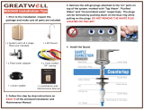
Remove nut (item 11) and blue tubing (item 12) from faucet (Leave the nut and plastic delrin
sleeve (item 10) on the blue tube).
Feed both the red and black tubing through the pre drilled hole in the sink/counter until faucet
is seated.
Step 6
Under the sink - on to the threaded faucet stem in order rst slide on the rubber gasket (item
6), the slotted washer (item 7), the white spacer with the open end UP (item 8), the hex nut
washer (item 9), and lastly secure with nut (item 11).
Step 8
Make sure the plastic delrin sleeve (item 10) is on the end of the blue tube, push the white
plastic insert (item 13) into the end of blue tubing with the delrin sleeve, insert the blue tube
(item 12) into the faucet stem and secure with nut (item 11).
Note:
DO NOT overtighten nut.
WATTSPremier Standard Faucet Installation - Part# 116001
Step 7
Step 9

Page 8
Adapt-a-Valve Installation - Part# 134007
Turn off the cold water supply to the faucet by turning the angle stop valve completely off.
Step 10
Step 11
Attach the adapt-a-valve as illustrated in the three photos above, choosing the conguration
that ts your plumbing. (When attaching the adapt-a-valve to straight pipe threads, use Teon
tape on the threads without the rubber washer.)
Caution:
Water supply line to the system must be from the cold water supply line only.
Hot water will severely damage your system.
Conguration for 3/8”
compression ttings
Conguration for 1/2”
compression ttings
Hot
Supply
Cold
Supply
Drain Saddle ts standard 1 ¼” – 1 ½” drain pipes
Drain Saddle Installation - Part# 164016
Step 12
Step 13
Step 14
The drain saddle must be mounted at least 1 ½” above the nut of the
P-trap or cross bar from the garbage disposal to insure proper drainage.
Assemble the drain saddle around the drain pipe at the best available
location. Using Phillips screw driver tighten screws evenly and securely
on both sides of the drain saddle. Keep the plastic compression nut off
at this time.
The small square black foam gasket with a circle cut out of the middle
must be applied to the inside of the drain saddle. Remove sticky tape
backing and stick to the drain saddle as shown.
1 Black compression nut 1 Semicircle bracket with opening
2 Screws 1 Foam gasket
2 Nuts for screws 1 Semicircle bracket
Gather the pieces of the drain saddle
Caution:
Do not over tighten the screws. It may crack the drain saddle.
If you have a garbage disposal, do not install the drain saddle near it.
Installation of the drain saddle must be either above the garbage disposal, or
if a second sink drain is available, install it above the cross bar on the second
drain. Installation of the drain saddle near a garbage disposal may cause
the drain line to plug. If no other installation of drain line is available, Watts
Premier offers drain line installation kit (part number 164020) that can be used
with garbage disposals.
Caution:

Page 9
Drill hole and Connect 3/8” Black Tube from Faucet to the Drain Saddle
Measure the 3/8” black tube from faucet to the drain saddle on the
drain pipe and make a straight cut to the correct length.
Slip black tube through black compression nut. Insert black tube
into the opening in the drain saddle and hand tighten the black nut,
and add 1/4 turn with a wrench.
The black 3/8” drain tube must be as SHORT and STRAIGHT as possible to the drain
saddle, making a downward slope from faucet to drain saddle to allow for proper
drainage. This is a gravity fed line and if there is any bend or dip in the tube, the rinse
water will not ow into the drain properly. Water may back up and come out the air
gap hole in the back of the faucet.
Step 17
IMPORTANT:
Step 16
Reverse Osmosis Module Mounting
Step 20 Determine best location for the RO module to be mounted to allow
for future system maintenance. The parts bag has 2 self tapping
screws. Using an electric drill with a Phillips bit, screw them into
the cabinet wall 6” apart and 16” from the bottom of the cabinet.
Do not cut any RO system tubes at this timeNote:
Step 19
Green Tube Connection
Step 18
Adapt-a-Valve - Part # 560070
Locate green tube from the RO Module. Remove a brass nut, plastic
sleeve and brass insert from the parts bag. To assemble, place the
brass nut on the green tube rst, then the sleeve (small tapered end
of sleeve must point to the end of tube) and then push the brass
insert all the way into the end of the tube. (See Picture)
Insert the green tube into the ¼” opening on the adapt-a-valve until
it stops. Slide the brass nut and sleeve down and thread onto the
male pipe threads. Use a ½” wrench to securely tighten the nut.
With the drain saddle secured onto the drain pipe, using a 1/4”
drill bit installed in your electric drill, insert the drill bit through the
opening in the drain saddle and drill through the drain pipe.
Step 15
Caution:
It is very important to keep the drill centered to prevent
damage of the drain saddle while drilling.

Page 10
Thread the brass tee (supplied in the parts bag) onto the brass
connection on the top of the tank and tighten using an adjustable
wrench.
Step 1
Step 2
Teon tape must be applied in a clockwise direction. Wrap 5 to 7
turns around the male pipe threads (MPT) on the Stainless Steel
tting on top of the tank.
Tank Tee Installation - Part# 131023
Do not apply Teon tape to the tee’s compression tting
threads. If taped, it will leak.
Caution:
Blue Tube Connection (From System)
Position the RO storage tank in a desired location. You may stand it
upright or lay it on its side (using the black plastic stand included).
Step 2
Step 1
Locate the blue tube from the RO module. Measure the tube from
the unit over to the storage tank and cut it to desired length. Remove
a brass nut, plastic sleeve and brass insert from the parts bag. To
assemble, place the brass nut on the tube rst, then the sleeve (small
tapered end of sleeve must point to the end of tube) and then insert
the brass insert all the way into the end of the tube. (See Picture)
Step 1
Red 1/4” Tube Connection (from faucet)
Using the white plastic union found in the parts bag, determine where
the 1/4” red tubing from the faucet and the 1/4” red tubing from the
RO membrane housing would join together comfortably. Cut red tube
from RO faucet to length leaving a straight cut edge. Insert the red
tube from RO faucet in one end of the white plastic union and the
red tube from RO membrane housing in the other end. Use a 5/8”
wrench to tighten both of the white plastic nuts securely.
Push the assembled blue tube into the brass tank tee until it stops.
Slide brass nut and plastic sleeve down until you can thread nut
onto the tee. Use a wrench to securely tighten the brass nut while
continuing to push the tube into the tee.
Step 3

Page 11
Remove the seal caps from both ends of the nal lter.
Cut the blue tubing between the RO faucet and the storage tank at
a desired location to splice in the in-line nal lter.
Step 1
Thread the two white plastic connectors into the nal lter and tighten
with a wrench.
Do not overtighten these connectors as it may damage them
or the nal lter.
Note:
A connection to a refrigerator / ice maker may be tee’d into this blue tube and should
be spliced in between the nal lter and the RO faucet.
Watts Premier offers an ice maker install kit part # 500010 (See Page 22).
Note:
Final Filter Installation
Step 2
With directional ow arrow on the lter pointing towards the faucet,
insert blue tubing from faucet into the tting on the nal lter (make
sure tube is pushed all the way into the tting). Tighten with a 5/8”
wrench securely. Repeat this step to connect the blue tube from the
tank into inlet side of the nal lter.
Step 3
Step 4
Step 1
Blue Tube Connection (From Faucet)
Step 2
Locate the blue tube from the RO faucet. Measure the tube from the
faucet over to the storage tank and cut it to desired length. Remove
a brass nut, plastic sleeve and brass insert from the parts bag. To
assemble, place the brass nut on the tube rst, then the sleeve (small
tapered end of sleeve must point to the end of tube) and then insert
the brass insert all the way into the end of the tube. (See Picture)
Push the assembled blue tube into the open brass tank tee until it
stops. Slide brass nut and plastic sleeve down until you can thread
nut onto the tee. Use a wrench to securely tighten the brass nut
while continuing to push the tube into the tee.

Page 12
Start up Instructions
Register by phone, fax, mail or internet. Watts Premier uses this information only to provide
you with a lter change reminder service. Pre-lters should be changed every 6 months and
the nal in-line lter annually. You may register your system via our web site at
www.premierH2o.com or call 1-800-752-5582 (within USA only) / FAX#: 450-675-7995.
For Warranty card Please see page 25-26.
If you have connected your RO system to a refrigerator / ice maker, make sure the ice maker
is off (do not allow water to ow to the ice maker) until ushing (Step 5) is complete and the
tank has been allowed to ll completely. Connection from the RO to the ice maker system
should have an in-line valve installed before the ice maker so it can easily be closed to prevent
water owing to the ice maker during start up and periodic maintenance. Your RO tank must
be allowed to ll up fully in order for the ice maker system to work properly.
After the Tank has lled, open the RO Faucet to ush the tank completely. You will know that
the tank is empty when the ow rate from the RO faucet is down to a trickle. Repeat this step
two more times. The fourth tank can be used for drinking.
Don’t Forget To Register!
Open the RO faucet and leave it open until water begins to trickle out (it will come out
slowly).
Step 4
Turn on the incoming cold water at the angle stop valve. Open the needle valve on the brass
Adapt-a-Valve by turning counter clockwise. Check the system for leaks and tighten any ttings
as necessary. (Check frequently over the next 24 hours to ensure no leaks are present).
Step 3
Step 2
Note:
Step 1
Close the RO faucet allowing the storage tank to ll with water. It may take 4 to 6 hours to
ll the tank completely depending on the production capability of the membrane, local water
temperature and water pressure.
Flushing of the tank 3 times is only necessary during the initial startup and after replacing the
membrane.
During the ll period you may hear water trickling due to the Reverse Osmosis Process.
Note:
Note:
Congratulations!
You have completed the installation of new your Reverse Osmosis system.
Please Follow the Startup Instructions.
The ushing process should take about a day to complete.

Page 13
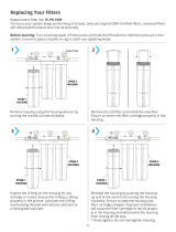
6 Month System Maintenance
Step 1
Step 3
Let system sit for one minute after the tank is empty to let the system depressurize before
attempting to remove lter housings.
Items needed:
√ Stage 1 - Sediment Filter (part #: 104017)
√ Stage 2 & 3 - Carbon Block Filter (part #: 101009-White End Caps)
Note:
The lter wrench pictured (Part # 164003) may be purchased from Watts Premier to aid with
twisting off lter housings but is not required.
Turn off the incoming water supply to the RO by turning the needle valve on the adapt-a-valve
clockwise until it stops.
Open the RO Faucet and allow water to drain from the tank until it is completely empty.
Step 2
Note:
Water may be saved in a container for drinking or to rinse system parts.
For more leverage you may leave the RO module attached to wall of
cabinet. If you are unable to access the module while it is mounted,
remove it prior to changing lters. Starting with the closest housing
(Stage 1), remove it by turning it clockwise (left), empty water, then
discard lter. Continue on to the 2
nd
housing (Stage 2) and 3
rd
housing
(Stage 3).
Step 4
Clean the lter housings (bowls) with a mild soap solution and rinse
with water. Check O-rings and lubricate with water soluble lubricant.
KY Jelly® or other water based lubricants may be used. Petroleum
based lubricants (such as Vaseline®) must not be used.
Step 5
Before re-installing the lter bowls back on to the system, check O-
rings to make sure they are still in place. *
Caution:
Note:
If you own a four stage system it will not have the third stage.
A four stage system has two vertical housings instead of three.
Insert a new sediment lter (cloth like appearance) into the 1st lter
housing which is the one on the water inlet side (green tubing from
the adapt-a-valve) of the RO system and re-install housing.
Step 6
Insert the new Carbon Block lter (White end caps & plastic netting)
into the second and third lter bowls and re-install housings.
Step 7
Step 8
Turn water supply on to the unit by turning the needle valve on the
adapt-a-valve counter clock wise.
Open the RO faucet and leave it open until water begins to trickle out
(it will come out slowly).
Step 10
Step 9
Close the RO faucet allowing the storage tank to ll with water. It
may take 4 to 6 hours to ll the tank completely depending on the
production capability of the membrane, local water temperature and
water pressure.
*Order lters by calling 1-800-752-5582 or buy online at www.premierH2o.com.
*
Loosen

Page 14
Annual Maintenance
Step 1
√ Stage 1 - Sediment Filter (part #: 104017)
√ Stage 2 & 3 - Carbon Block Filter (part #: 101009-White end caps)
√ Stage 5 - 10” Final Polishing lter (part # 560010)
√ 1/2 Cup of hydrogen peroxide or common household bleach.
*Order lters by calling 1-800-752-5582 or buy online at www.premierH2o.com.
Note:
Sanitizing of unit is recommended.
Perform steps 1 through 5 in the Six Month System Maintenance (Page 13).
Note:
If not sanitizing the system skip to step 8.
Step 3
Step 4
Step 5
Step 6
Remove the RO membrane from its housing and rest in a clean sanitary place. (Refer to
“Membrane Replacement” section on page 15 for directions on removing the membrane).
Replace cap onto empty membrane housing and re-connect green tubing.
Step 2
Leaving the lters out, replace stage 2 and 3 empty lter housings (hand tight) onto unit.
Measure & pour either 1/2 cup of hydrogen peroxide or common household bleach into the
1st lter housing (Stage 1) and hand tighten onto unit.
With the RO faucet in the closed position turn on the incoming water supply to the system by
turning the adapt-a-valve counter clockwise. Wait 1 minute for the unit to pressurize. Turn
on the RO faucet and let the water run for 30 seconds. Turn off the RO faucet and let the unit
rest for 2 minutes. Finally, open the RO faucet and let the water run for 5 more minutes.
Turn off the incoming water supply to the system by turning the adapt-a-valve clockwise
until it stops. Keep the RO faucet open until the storage tank is completely drained.
Open the membrane housing and re-install the RO membrane while making sure not to kink
the O-rings. (Refer to “Membrane Replacement” section on page 15 for directions on
installing the membrane). Tighten the cap back on the housing and reconnect green tubing.
Step 7
Remove lter housings Stage 1, 2 and 3 and empty of water.
Before re-installing the lter bowls back on to the system , check O-rings to make sure
they are still in place and lubricate with water soluble lubricant.
Caution:
Insert the new sediment lter (cloth like appearance) into the 1
st
lter housing which is the one
on the water inlet side (green tubing from the adapt-a-valve) of the RO system and
re-install housing.
Step 8
Insert the new Carbon Block lter (White End Caps) into the 2nd and 3rd housing and
re-install housing.
Step 9
Step 11
Follow Steps 8 through 10 in the Six Month System Maintenance (Page 13) for startup
directions.
Tip:
This is a good time to check the air pressure in your storage tank. For instructions
please see page 16.
Step 10
The nal in-line lter is located on the blue tube between the storage tank and the RO faucet.
Remove it by loosening the compression ttings on both ends of the lter and replace with
new lter. (Discard used nal lter after santizing)
Note:
The arrow on the nal lter must be pointing towards the RO faucet / away from the
RO storage tank.

Page 15
Membrane Replacement
Use a 5/8” wrench to remove the Green Tube tting on the left side
of the horizontal membrane housing (end with one elbow).
Step 1
Step 2
Step 3
Step 4
Step 5
Note:
This reverse osmosis system contains a replaceable component (the RO membrane) which is critical to the efciency of
the system. Replacement of this reverse osmosis membrane should be with one of identical specications as dened by
Watts Premier to assure the same efciency and contaminant reduction performance.
Membranes have a life expectancy between 2 and 5 years, depending on the incoming water conditions and
the amount the RO system is used. This reverse osmosis membrane is critical for effective reduction of total
dissolved solids (TDS). The product water should be tested periodically to verify that the system is performing
satisfactorily.
Normally, a membrane would be replaced during a semiannual or annual lter change. However, if at any time
you notice a reduction in water production or an unpleasant taste in the reverse osmosis water, it could be time
to replace the membrane. Watts Premier recommends replacing the membrane when TDS reduction falls below
75%.
A water sample may be sent to Watts Premier for a free diagnosis of your membrane
performance. To send a water sample, use two (2) clean containers and ll ½ cup of tap water
in one container and ½ cup of reverse osmosis water in 2nd container. Clearly label each
sample. Send the samples to the address listed on the cover of this manual attention “Water
Samples”. Watts Premier will test the water and mail or call you with the results.
Note:
Step 1
Turn off the incoming water supply to the RO by turning the needle
valve on the adapt-a-valve clockwise until it stops.
Open the RO Faucet and allow water to drain from the tank until it
is completely empty.
Step 2
Removing the membrane:
Installing the membrane:
Follow the Start Up Instructions on page 12.
Remove the cap from the membrane housing by turning it counter
clockwise to loosen.
A double sided wrench may be purchased from Premier to aid with
loosening the cap / lter housings. (Part # 164003)
Remove membrane housing from the holding clips. Using a pair of
pliers, grip the PVC tube of the RO membrane and pull rmly on the
membrane to remove from the housing and discard.
Lubricate the O-rings on the new membrane with a water soluble
lubricant such as KY Jelly ®. Insert the end with the two black
O-rings rst into the housing.
Once membrane has been inserted into the housing you must take
your thumbs and give a rm push to properly seat the membrane.
Replace membrane housing cap and tighten.
After replacing membrane housing into clips, attach the green tube
to the elbow on cap using 5/8” wrench.
Step 6
Step 7
Loosen

Page 16
Once all water in the tank is purged, check air pressure using an air pressure gauge, it should
read between 5 - 7 PSI. (Digital air pressure gauge is recommended)
Check Air Pressure in the Tank
Important:
Step 3
Check air pressure only when tank is empty of water!
Step 1
Turn off the incoming water supply to the RO by turning the needle
valve on the adapt-a-valve clockwise until it stops. (Follow the green
tube away from the RO system to nd the adapt-a-valve.)
Open the RO Faucet and allow water to drain from the tank until
it is completely empty.
Step 2
Check air pressure in the storage tank when you notice a decrease in available water from
the RO system. Air can be added with a bicycle pump using the schrader valve that is located
on the lower side of the tank behind the blue plastic cap.
Tip:
When water from the RO faucet slows to a trickle, with the faucet still in the open position, you
may add air to the tank to purge any left over water, this will ensure that the tank is completely
empty.
Procedure for Extended Non-Use (More than 2 months)
Turn off the water supply by turning the “T” on the adapt-a-valve clockwise until it stops and
open the RO faucet to empty the storage tank (Save a few ounces of RO water). Once the
storage tank is empty, remove the membrane and place it in a sealed plastic bag with the RO
water saved earlier and store in your refrigerator.
For restart, reinstall membrane (See page 15 for membrane installation procedure) and follow
startup procedure on page 12.
Step 4
Follow startup procedure on page 12.

Page 17
TROUBLE SHOOTING
Problem Cause Solution
1. Low/Slow Production Low Water Pressure Assure a minimum of 40 psi incoming water pressure.
Premier sells a booster pump if home water pressure is
low. Make sure water supply is turned on and Adapta
Valve is all the way open.
Crimps in tubing Check tubing and straighten or replace as necessary.
Clogged pre-lters Replace pre-lters.
Fouled membrane Replace membrane and ow restrictor.
2. Milky colored Water Air in system Air in the system is a normal occurrence with initial
start up of the RO system. This milky look will
disappear during normal use within 1-2 weeks. If
condition reoccurs after lter change, drain tank 1 to 2
times.
3. Water constantly Low water pressure See #1 Above
running, unit will not
shut off Crimp in supply tube Check tubing and straighten or repair as necessary.
High water pressure Check incoming water pressure to make sure it does
not exceed 80 psi. A pressure relief valve may be
necessary.
High pressure in Tank Empty storage tank of water. Set tank air pressure
between 5-7 psi. See previous page.
Low Pressure in Tank Use a Digital Air Gauge for best results. The empty
tank pressure should be 5-7 psi. See page 16.
4. Noise / Water from faucet Crimp or restriction Check tubing and straighten or repair as necessary.
vent hole or noise from in drain line Straighten all drain lines. Clear blockage. Cut off any
drain. Excess tubing
Drain tube clogged Caused from dishwasher or garbage disposal.
Disconnect the 3/8” black line at the drain, clean the
3/8” black line out with a wire, then reconnect. Blowing
air through the line will not always remove the clog.
5. Small amount of water in System starting up Normally it takes 4-6 hours to ll tank. Note: low
storage tank incoming water pressure and/or temperature can
drastically reduce production rate.
Low water pressure See #1 above.
To much air in tank Tank air pressure should be 5-7 psi when empty of water.
If below 5 psi add air or bleed if above 7 psi.
Check only when tank is empty of water.
See previous page.
6. Water leaks from the blue Not properly tightened Tighten the bowl.
or white lter housing Kinked O-ring Turn off the water supply and release the pressure.
Replace the O-ring if necessary. Then lubricate it and
make sure the O-ring is seated in the lter bowl
properly before reinstalling the lter bowl.
7. Low water ow from faucet Check air pressure in tank Use a Digital Air Gauge for best results. The empty
tank pressure should be 5-7 psi. See page 16.

Page 18
Item # Part # Description
17 131012 SLEEVE-PLASTIC-1/4”
18 131017 INSERT-BRASS-1/4”
19 131021 HEX NIPPLE-BRASS-1/4
20 131023 TEE-TANK-BRASS-1/4CX1/4CX1/4F
21 134003 VALVE-SHUT OFF 1/4MPT QUICK CONNECT
22 134007 ADAPTA VALVE
22 a 146025 ADAPTA VALVE WASHER
23 a 137013 BRACKET-4SV-STEEL-WHITE
23 b 137026 BRACKET-5SV-STEEL-WHITE
24 146001 SCREW-#10-3/4” PHIL PANHEAD X 6 (Filter Lid)
25 146004 SCREW-#10-1” PHIL PANHEAD X 2 (Mem. Clip)
26 164006 CLIP-MTG-MEM-VESSEL
27 164016 DRAIN SADDLE 3/8”
28 119028 TANK STAND
29 113029 O-RING FILTER HOUSING
30 199348 MANUAL 4SV & 5SV PR-14
31 610109 GREEN TUBING 1/4”
33 610117 BLUE TUBING 1/4”
Item # Part # Description
1 a 100004 GAC-IL-6”-1/4 F
1 b 100014 GAC-IL-10”-1/4 F
2 104017 SED-SPUN-10”-5M-CTG
3 a 101009 CARBONBLOCK-10”-5M-CTG
3 b 100036 GAC 10” - 56 Cu In
4 a 110004 *MEM-18 GPD
4 b 110009 *MEM-25 GPD
5 a 113002 LID-BLACK 1/4” FPT
5 b 113005 LID-WHITE 1/4” FPT
6 a 113019 HOUSING-FILTER 10” BLUE
6 b 113021 HOUSING-FILTER 10” WHITE
7 113032 VESSEL-MEMBRANE-HOUSING
8 a 116001 FAUCET-AG-CHROME
9 a 119004 TANK-PRESURE-3 GAL-BLUE
9 b 119007 TANK-PRESURE-3 GAL WHITE
12 125017 CONNECTOR-PLASTIC-1/4CX1/4M
13 125031 ELBOW-PLASTIC-1/4CX1/8M-90
14 125034 ELBOW-PLASTIC-1/4CX1/4M-90
15 125041 UNION-PL-1/4CX1/4C
16 131002 NUT-BR-1/4C”
1
2
3 3
4
5 5 5
6
6 6
7
8
9
10
11
11
12
12
13
14
16
16
17
18
18
17
16
20
19
19
22
22
13
23
26
27
28
29
Green
Green
Green
Blue
Blue
Blue
Blue
Blue
Red
Red
Black
Black
Black
5 Stage Reverse Osmosis System
1
2
3 3
4
5 5 5
6
6 6
7
8
9
12
12
13
14
16
17
18
18
17
16
20
19 19
22
22
13
23
26
27
28
29
Green
Green
Green
Blue
Blue
Blue
Blue
Blue
Red
Red
Black
5 Stage Reverse Osmosis System
5-7 PSI
14
21
15
Red

Page 19
California Certication

Page 20
RECOMMENDED REPLACEMENT PARTS AND CHANGE INTERVALS:
Note: Depending on incoming feed water conditions replacement time frame may vary.
Description Change time Frame Cost
Sediment Pre-lter: #5m-10 6 Months $ 3.50
Carbon Pre-lter: #5MCB 6 Months $10.50
Final Carbon lter #1m-6/#1M-10 12 Months $6.75 / $9.50
R.O. Membrane: #TFM-24 2 to 5 years $64.95
Depending on water chemistry, water temperature, and water pressure Watts Premier’s R.O. Systems production and performance will vary.
Efciency rating means the percentage of the inuent water to the system that is available to the user as reverse osmosis treated water under
operating conditions that approximate typical daily usage. Recovery rating means the percentage of the inuent water to the membrane portion of
the system that is available to the user as reverse osmosis treated water when the system is operated without a storage tank or when the storage
tank is bypassed. There is an average of 4 gallons of reject water for every 1 gallon of product water produced.
REFER TO OWNER’S INSTALLATION/SERVICE MANUAL FOR FURTHER MAINTENANCE REQUIREMENTS AND WARRANTY INFORMATION.
Phone: (480) 675-7995 Fax: (623) 866-5666 Email: [email protected]
GENERAL USE CONDITIONS:
1. System to be used with municipal or well water sources treated and tested on regular basis to insure bacteriological safe quality. DO NOT use with water that
is micro biologically unsafe or unknown quality without adequate disinfection before and after the system. Systems certied for cyst reduction may be used on
disinfected water that may contain lterable cysts.
2. Operating Temperature: Maximum: 100°F (40.5°C) Minimum: 40° (4.4°)
3. Operating Water Pressure: Maximum: 100 psi (7.0kg/cm2) Minimum: 40 psi (2.8kg/cm2)
4. pH 2 to 11
5. Maximum iron present in incoming feed water supply must be less than 0.2 ppm.
6. Hardness of more than 10 grains per gallon (170 ppm) may reduce membrane life expectancy.
7. Recommend TDS (Total Dissolved Solids) not to exceed 1800 ppm.
Watts Premier Inc.
8716 W Ludlow Drive Suite #1
Peoria, AZ 85381
California Certication # 00-1452
5 SV Deluxe, CRO-TFM-5SV, Ultra 5 and Pur-Tek, Watts 25, Watts RO-4, Watts RO-5, RO-TFM-4SV, RO-TFM-5SV
System conforms to NSF Standard 58 for specic claims.
This system has been tested according to NSF/ANSI 58 for reduction of the substances listed below. The concentration of the indicated substances in water
entering the system was reduced to a concentration less than or equal to the permissible limit for water leaving the system as specied in NSF/ANSI 58. This
system has been tested for the treatment of water containing pentavalent arsenic (also known as As (V), As (+5), or arsenate) at concentrations of 0.30 mg/L or
less. This system reduces pentavalent arsenic, but may not remove other forms of arsenic. This system is to be used on water supplies containing a detectable free
chlorine residual at the system inlet or on water supplies that have been demonstrated to contain only pentavalent arsenic. Treatment with chloramine (combined
chlorine) is not sufcient to ensure complete conversion of trivalent arsenic to pentavalent arsenic, Please see the Arsenic Facts section of the Performance Data
Sheet for further information.
Avg. In. Avg. Eff. % Reduction pH Pressure Max Eff. Inf. challenge Max Allowable
(mg/L) (mg/L) mg/L concentration concentration
mg/L mg/L
Arsenic (Pentavalent) 334.62 ug/L 5.039 ug/L 98.4% 50psi 19 ug/L 0.30±10% 0.010 mg/L
Barium Reduction 10.2 0.13 98.7% 7.24 50psi 0.27 10.0±10% 2.0
Cadmium Reduction 0.031 0.0001 99.7% 7.49 50psi 0.0009 0.03±10% 0005
Chromium (Hexavalent) 0.30 0.006 98.0% 7.24 50psi 0.013 0.03±10% 0.1
Chromium (Trivalent) 0.30 0.003 99.0% 7.24 50psi 0.008 0.03±10% 0.1
Copper Reduction 3.0 0.04 98.7% 7.64 50psi 0.06 3.0±10% 1.3
Cysts 222,077#/ml 10 #/ml 99.99% 50psi 58 minimum 50,000/mL N/A
Fluoride Reduction 8.0 0.33 95.9% 7.49 50psi 0.47 8.0±10% 1.5
Lead Reduction 0.15 0.004 97.3% 7.49 50psi 0.008 0.15±10% 0.0107
Perchlorate 0.10 0.003 96.5% 7.39 50 psi 0.005 mg/L 0.10±10% 0.006
Radium 226/228 25pCi/L 5pCi/L 80.0% 7.24 50psi 5pCi/L 25pCiL±10% 5pCiL
Selenium 0.10 <0.001 99.0% 50psi <0.001 0.10±10% 0.05
TDS 760 85 88.0% 5.94 50psi 100 750±40mg/L 187
Turbidity 81 NTU 0.15 NTU 99.8% 50psi 0.28 NTU 11±1 NTU 0.5 NTU
Recovery - 18.0% Daily Production Rate - 11.0 GPD Efciency - 10.4%
* All Prices Subject to change without notice
/