Watts ZRO-4 Installation guide

Category
Sanitary ware
Type
Installation guide

Watts ZRO-4: Experience the Purity - Advanced Reverse Osmosis Technology for Your Home's Water Needs

The Watts ZRO-4 Reverse Osmosis System is a state-of-the-art water treatment solution designed to provide your household with an exceptional drinking water experience. Equipped with a 4-stage filtration process, this system effectively removes impurities, heavy metals, and contaminants, including arsenic, lead, and chlorine, leaving you with clean, refreshing water.

Installation, Operation
and Maintenance Manual
Zero Waste Reverse Osmosis System
Model PWSYS-RO-STD4-ZRO
IOM-WQ-PWSYS-RO-STD4-ZRO
Table of Contents Pages
Operational Parameters...................................3
Contents of Reverse Osmosis System........................3
Tools Recommended For Installation .........................3
Drill a Hole for the Faucet in a Porcelain Sink ...................3
Punch a Hole for the Faucet in a Stainless Steel Sink.............3
How to use Quick-Connect Fittings ..........................4
Watts Top Mount Faucet Installation .........................5
Adapt-A-Valve™ Installation ...............................5
Reverse Osmosis Module Mounting .........................5
Green Tube Connection...................................6
Black Tube Connection ...................................6
Check Air Pressure in the Tank .............................6
Tank Ball Valve Installation .................................6
Final Filter Installation.....................................6
Start up Instructions .....................................7
6-Month Maintenance ....................................8
Annual Maintenance .....................................8
Membrane Replacement ..................................9
Procedure for Extended Non-Use (More than 2 months) ..........9
Troubleshooting........................................10
Parts List .............................................11
Arsenic Facts..........................................12
Service Record ........................................13
Limited Warranty .......................................16
Model PWSYS-RO-STD4-ZRO
PURE WATER
System tested and certified by NSF International
against NSF/ANSI Standard 58 for the reduction
of the claims specified on the performance data
sheet.
Note: Do not use with water that is microbiologically unsafe or
of unknown quality without adequate disinfection before or after
the system. Systems certified for cyst reduction may be used
on disinfected waters that may contain filterable cysts.
Important
Please read the entire manual before proceeding with the
installation and startup. Your failure to follow any attached
instructions or operating parameters may lead to the product’s
failure.
Save manual for future reference.
2
Introduction
Thank you for your purchase of a state of the art Watts Reverse
Osmosis (RO) water treatment system. Water quality concerns are
becoming more of a focus for the public. You may have heard about
contaminants in the drinking water, such as Arsenic, Chromium,
Cryptosporidium or Giardia. There may also be some local water
issues such as high levels of Lead and Copper. This Watts water
treatment system has been designed and tested to provide you with
high quality drinking water for years to come. The following is a brief
overview of the system.
Your Reverse Osmosis System:
Osmosis is the process of water passing through a semi-permeable
membrane in order to balance the concentration of contaminants
on each side of the membrane. A semi-permeable membrane is a
barrier that will pass some particles like clean drinking water, but not
other particles like arsenic and lead.
Reverse osmosis uses a semi-permeable membrane; however, by
applying pressure across the membrane, it concentrates contami-
nants (like a strainer) on one side of the membrane, producing crystal
clear water on the other. This is why RO systems produce both clean
drinking water and waste water that is flushed from the system. This
reverse osmosis system also utilizes carbon block filtration technol-
ogy and can, therefore, provide a higher quality drinking water than
carbon filtration systems alone.
Your system is a 4-Stage RO which is based upon separate treat-
ment segments within the one complete water filtration system.
These stages are as follows:
Stage 1 – Sediment filter, recommended change 6 months.
The first stage of your RO system is a five-micron sedi-
ment filter that traps sediment and other particulate matter
like dirt, silt and rust which affect the taste and appear-
ance of your water.
Stage 2 – Carbon filter, recommended change 6 months.
The second stage contains a five-micron carbon block
filter. This helps ensure that chlorine and other materials
that cause bad taste and odor are greatly reduced.
Stage 3 - Membrane, recommended change 2-5 years.
Stage 3 is the heart of the reverse osmosis system, the
RO membrane. This semi-permeable membrane will ef-
fectively take out TDS, Sodium and heavy metals such as
arsenic, copper, and lead, as well as cysts, such as Giar-
dia and cryptosporidium. Because the process of making
this high quality drinking water takes time, your RO water
treatment system is equipped with a storage tank.
Stage 4 - Carbon in-line filter, recommend change 6 - 12
months.
The final stage is an in-line granular activated carbon
(GAC) filter. This filter is used after the water storage tank,
and is used as a final polishing filter.
Note: Filter & Membrane life may vary based upon local water
conditions and/or use patterns.
System Maintenance
Just because you can not taste it, does not mean that it is not there.
Contaminants such as lead, chromium and arsenic (to name a few)
are undetectable to the taste. Additionally, over time if you do not
replace the filter element, other bad tastes and odors will be appar-
ent in your drinking water.
This is why it is important to change out your filter at the recom-
mended intervals as indicated in this system manual. When replacing
the filter elements, pay special attention to any cleaning instructions.
Should you have any further questions please refer to our website
at www.watts.com or call our customer service department at
1-800-244-1299.
With proper installation and maintenance, this system will provide
you with high quality water for years to come. All of Watts water
enhancement products are rigorously tested by independent labora-
tories for safety and reliability. If you have any questions or concerns,
please contact our Customer Service department at 1-800-244-
1299 or refer to our on-line troubleshooting at www.watts.com.
3
Operating Temperatures Maximum 100°F (37.8°C) Minimum 40°F (4.4°C)
Operating Pressure
Maximum 85psi
(6.0 kg/cm2)
Minimum 40psi
(2.80 kg/cm2)
pH Parameters Maximum 11 Minimum 2
Iron Maximum 0.2 ppm
TDS (Total Dissolved Solids) < 1800 ppm
Turbidity < 5NTU
Operational Parameters
Do not use with water that is microbiologically unsafe or of
unknown quality without adequate disinfection before or after
the system. System is intended to be installed on the cold water
line only.
Contents of Reverse Osmosis (RO) System
1 Tank
1 RO Module
1 Parts Bag – With a 10" Final Filter
1 Faucet Bag
1 Manual
If any of the items are missing please contact prior to installing.
Tools Recommended for Installation
• 1¼" Hole Saw Bit for Faucet opening
Round Knockout Punch for Stainless
Sinks 1¼"
• Adjustable Wrench
• Sharp Knife
1
2" &
5
8" Open End Wrenches
• Phillips Screw Driver
• Needle Nose Pliers – Adjustable Pliers
• Electric Drill
1
8" Drill Bit
1
4" Drill Bit
3
8" Drill Bit
Hardness: Recommended hardness not to exceed 10 grains per
gallon, or 170ppm. System will operate with hardness over 10 grains
but the membrane life may be shortened. Addition of a water soft-
ener may lengthen the membrane life.
Water Pressure: The operating water pressure in your home should
be tested over a 24 hour period to attain the maximum pressure.
If the incoming water pressure is above 85psi a pressure regula-
tor is recommended and if over 100psi then a pressure regulator is
required.
Copper Tubing: Reverse Osmosis water should not be run through
copper tubing as the purity of the water will leach copper causing
an objectional taste in water and pin holes may form in the tubing.
Watts supplies speciality filters that can be used if copper tubing
follows the Reverse Osmosis unit. Be sure to follow any state or local
regulations during installation.
Drill a Hole for the Faucet in a Porcelain Sink
Note: Most sinks are predrilled with 1½" or 1¼" diameter hole
that you can use for your RO faucet. (If you are already using it
for a sprayer or soap dispenser, see Step 2).
Caution: Porcelain sinks are extremely hard and can crack or
chip easily.
Use extreme caution when drilling. Watts accepts no responsi-
bility for damage resulting from the installation of faucet.
Step A – Determine desired location for
the RO faucet on your sink
and place a piece of masking
tape on over where the hole is
to be drilled. Mark the center
of the hole on the tape.
Step B – Using a variable speed drill
set on the slowest speed, drill
a
1
8" pilot hole through both
porcelain and metal casing
of sink at the marked center
of the desired location. Use
lubricating oil or liquid soap
to keep the drill bit cool (If drill
bit gets hot, it may cause the
porcelain to crack or chip).
Step C – Using a 1¼" hole saw, pro-
ceed to drill the large hole.
Keep drill speed on the slow-
est speed and use lubricating
oil or liquid soap to keep the
hole saw cool during cutting.
Step D – Make sure the surroundings
of the sink are cooled before
mounting the faucet to the
sink after drilling and remove
all sharp edges.
STEP 1
Punch a Hole for the Faucet in a Stainless
Steel Sink
Note: If mounting faucet to a Stainless
Steel Sink, you will need a 1¼" Hole
Punch. The faucet opening should be
centered between the back splash
and the edge of the sink, ideally on the
same side as the vertical drain pipe.
Step A – Drill a ¼" pilot hole. Use a
1
2"
Hole Punch and an adjustable
wrench to punch the hole in the
sink. Change to the 1¼" Hole
Punch to enlarge the hole
The faucet can now be installed.
OR
4
How to use the Quick-Connect fittings on the RO Module
To make a connection, the tube is simply pushed into the fitting.
Place a piece of tape
1
/2" from end of tube to indicate how far the
tube should be inserted. The unique patented Quick-Connect
locking system holds the tube firmly in place without deforming it or
restricting flow.
Cut the tube square. It is essential that the outside diameter be free of score marks
and that burrs and sharp edges be removed before inserting into fitting.
Fitting grips before it seals. Ensure tube is pushed into the tube stop.
Push the tube into the fitting, to the tube stop. The collet (gripper) has stainless
steel teeth which hold the tube firmly in position while the O-ring provides a perma-
nent leak proof seal.
Pull on the tube to check that it is secure. It is a good practice to test the system
prior to leaving site and /or before use.
To disconnect, ensure the system is depressurized before removing the tube. Push
in collet squarely against face of fitting. With the collet held in this position, the tube
can be removed. The fitting can then be reused.
5
Adapt-A-Valve™ Installation
Caution: Water supply line to the system must be from the cold
water supply line only. Hot water will severely damage your
system.
Configuration for
1
2 inch valve
(using no brass fittings)
Figure 1
Configuration for
3
8 inch valve
(using brass fittings)
Figure 2
Placement diagram for Adapt-A-Valve™
Figure 3
Step A – Turn off the hot and cold water supply to the faucet by
turning the angle stop valves off.
Step B – Remove water supply line from faucet to the angle stop
valves.
Step C – Attach the Adapt-A-Valve™ as illustrated in Fig 2, Fig 3,
choosing the configuration that fits your plumbing needs
Step D – Re-attach the water supply line to the fittings attached to
the angle stop valves.
Step E – Completed Valve installation Figure: 3.
Step F – Insert Green tube into cold water Adapt-A-Valve™ until it
stops.
Step G – Insert Black tube into hot water Adapt-A-Valve™ until it
stops.
Caution: Water supply line to the system must be from the cold
STEP 3
Figure 1
Figure: 2
Figure: 3
Hot
Supply
Cold
Supply
STEP 4
Reverse Osmosis Module Mounting
Step A – Determine best location for the
RO module to be mounted to
allow for future system main-
tenance. The parts bag has 2
self-tapping screws. Using an
electric drill with a Phillips bit,
screw them into the cabinet
wall 6" apart and 16" from the
bottom of the cabinet.
Note: Do not cut any RO system tubes at this time
STEP 2
Watts Chrome Top Mount
Faucet Installation
Gather and identify the faucet pieces.
Step A - Remove faucet base and faucet spout from their respective
plastic bags. From above the sink, feed the faucet tubing
& toggle bolt down through the 1¼" mounting hole in the
sink. Ensure that the soft rubber gasket has the protec-
tive white paper removed from both sides and is uniformly
positioned in between the base of the faucet and the top of
the sink.
Step B - Align the faucet base so that the handle is on the right side
and the base is sitting flush on the sink top. Using a phillips
head screwdriver, turn the screw located down the hole
where the spout will be installed, clockwise until the toggle
bolt secures the faucet base snug onto the sink top.
Step C - Once the faucet base is securely fastened to the sink top,
insert the faucet spout into the faucet base until it is fully
seated. Turn the handle up (away from you) to the “OFF”
position.
Step D - Connect the loose end of the
3
8" blue plastic tubing from
the faucet to the
3
8" plastic fitting from the final inline filter.
MINIMUM MAXIMUM
Mounting Hole Size 1" 1
1
4"
Torque on Toggle Bolt 5 lb.in. (max)
6
STEP 5
Green Tube Connection
Step A – Locate green tube attached to the
RO Module. Insert the open end of
the green
1
4" tube into the open
1
4"
quick-connect fitting on the Adapt-
A-Valve™ making sure the tube is
pushed in all the way to the tube
stop.
Step B – Connect the green tube from the RO
module to the Adapt-A-Valve™ that
is connected to the cold water angle
stop valve. Leave enough tube so it is not kinked and cut
the tube to the desired length.
STEP 6
Black Tube Connection
Step A – Locate black tube attached to the
RO Module. Insert the open end of
the black
1
4" tube into the open
1
4"
quick-connect fitting on the Adapt-
A-Valve™ making sure the tube is
pushed in all the way to the tube
stop.
Step B – Connect the black tube from the RO
module to the Adapt-A-Valve™ that
is connected to the hot water angle
stop valve. Leave enough tube so it is not kinked and cut
the tube to the desired length.
STEP 9
Final Filter Installation
Step A – Locate
3
/8" blue tubing in parts bag. The final polishing filter
is clipped onto the top of the membrane housing. Connect
one open end of
3
/8" blue tubing to the quick-connect fitting
labeled "Faucet" located on the final polishing filter. Make
sure that the tube is pushed in all the way to the tube stop.
Step B – Connect the other end of the
3
/8" blue tubing connected to
the in-line filter to the quick-connect fitting located on the
faucet shank.
Note: A connection to a refrigerator / ice maker may be tee’d
into this blue tube and should be spliced in between the final
filter and the RO faucet.
STEP 7
Check Air Pressure in the Tank
Note: Check air pressure when tank is empty of water!
Check air pressure in the storage tank when you notice a de-
crease in available water from the RO system. Air can be added
with a bicycle pump using the schrader valve that is located on
the lower side of the tank behind the blue plastic cap.
Step A – Turn off the incoming water
supply to the RO by turning the
knob on the Adapt-A-Valve™
clockwise until it stops. (Follow
the green tube away from the
RO system to find the Adapt-A-
Valve™.)
Step B – Open the RO Faucet and allow water to drain from the tank
until it is completely empty.
Tip: When water from the RO faucet slows to a trickle, with the
faucet still in the open position, you may add air to the tank to
purge any left over water. This will ensure that the tank is com-
pletely empty.
Step C – Once all water in the tank is purged, check air pressure us-
ing an air pressure gauge, it should read between 5 - 7psi.
(Digital air pressure gauge is recommended)
Step D – Follow startup procedure on Page 7.
Step A – Teflon
®
tape must be applied
in a clockwise direction. Wrap
(4 to 8 turns) around the male
pipe threads (MPT) on the
stainless steel fitting on top of
the tank.
Step B – Thread the Quick-Connect
ball valve (supplied in the
parts bag) onto the stainless
steel connector on the tank.
Caution: Do not Teflon
®
tape the
plastic elbow threads as this may cause
leaks.
Tank Ball Valve Installation
STEP 8
Teflon
®
is a registered trademark of E.I. Dupont de Nemours & Company.
7
Start Up Instructions
Warning: To prevent the possibility of electrical shock, clean up
any water on cabinet floor and dry all water from outside of RO
unit.
Step A– Turn on the incoming cold and hot water at the angle stop
valves by turning the knob on the Adapt-A-Valve™ coun-
terclockwise. Check the system for leaks and tighten push
to be further in any fittings as necessary. (Check frequently
over the next 24 hours to ensure no leaks are present).
Note: If you have connected your RO system to a refrigerator /
ice maker, make sure the ice maker is off (do not allow water to
flow to the ice maker) until flushing is complete and the tank has
been allowed to fill completely. Connection from the RO to the
ice maker system should have an in-line valve installed before
the ice maker so it can easily be closed to prevent water flowing
to the ice maker during start up and periodic maintenance. Your
RO tank must be allowed to fill up fully in order for the ice maker
system to work properly.
Step B – Plug the 24 volt transformer power cord connector into the
RO wire harness connector (labeled Transformer).
Step C – Plug the transformer into the electrical outlet under the
sink.
Step D – Open the RO faucet and leave it open until water begins to
trickle out (it will come out slowly).
Step E – After water trickles out of the faucet, close the RO faucet
allowing the storage tank to fill with water. It may take 4 to
6 hours to fill the tank completely depending on the pro-
duction capability of the membrane, local water tempera-
ture and water pressure.
Note: Ensure Ball Valve on the RO storage tank is open.
Note: During the fill period, you may hear water trickling due to
the Reverse Osmosis Process.
Step F – After the Tank has filled, open the RO Faucet to flush the
tank completely to remove carbon particles from final filter.
You will know that the tank is empty when the flow rate
from the RO faucet is down to a trickle. Repeat this step
two more times. The fourth tank can be used for drinking.
Note: Flushing of the tank 3 times is only necessary during the
initial startup and after replacing the membrane.
Important: Your reverse osmosis system contains replaceable
treatment components that are critical for effective containment
reduction. Periodic inspection and following proper system
maintenance is critical for continued performance.
8
Step E – Clean the filter housings (bowls)
with a mild soap solution and
rinse with water. Check O-rings
and lubricate with water soluble
lubricant. KY Jelly
®
, canola oil
or other water based lubricants
may be used. Petroleum
based lubricants (such as
Vaseline
®
) must not be used.
Caution: Before re-installing the filter bowls back on to the sys-
tem, check O-rings to make sure they are still in place.
Step F – Insert a new sediment filter
(cloth like appearance) into
the 1st filter housing which is
the one on the water inlet side
(green tubing from the Adapt-
A-Valve™) of the RO system
and re-install housing.
Step G – Insert the new Carbon Block
filter (White end caps & plastic netting) into the second and
third filter bowls and re-install housings.
Do not over-tighten filter housing, overtightening may damage
O-ring(s), cause water leaks, or affect system performance.
Step H – Turn water supply on to the unit by turning the knob on the
Adapt-A-Valve™ counterclockwise.
Step I – Open the RO faucet and leave it open until water begins to
trickle out (it will come out slowly).
Step J – Close the RO faucet allowing the storage tank to fill with
water. It may take 4 to 6 hours to fill the tank completely
depending on the production capability of the membrane,
local water temperature and water pressure.
6-Month System Maintenance
Order filter by calling Watts at 1-800-224-1299
Item Needed: EDP# 7100110
Includes:
• (1) Sediment Filter • (1) Carbon Block Filter
Step A – Turn off the incoming water supply to the RO by turning the
knob on the Adapt-A-Valve™ clockwise until it stops.
Step B – Open the RO Faucet and allow water to drain from the tank
until it is completely empty.
Note: Water may be saved in a container for drinking or to rinse
system parts.
Step C – Let system sit for 10 to 15
minutes after the tank is empty
to let the system depressurize
before attempting to remove
filter housings.
Step D – For more leverage you may
leave the RO module attached
to wall of cabinet. If you are
unable to access the module
while it is mounted, remove it
prior to changing filters. Start-
ing with the closest housing
(Stage 1), remove it by turning
it clockwise (left), empty water,
then discard filter. Continue on
to the 2nd housing (Stage 2)
and 3rd housing (Stage 3).
Note: If you own a 4-Stage system, it will not have the third
stage. A 4-Stage system has two vertical housings instead of
three.
Annual Maintenance
Order filter by calling Watts at 1-800-224-1299
Item Needed: # 7100115
1/2 cup of hydrogen peroxide or household bleach.
Includes:
• (1) Sediment Filter • (1) Membrane
• (1) Carbon Block Filters • (1) Final Inline Filter
Note: Sanitizing of unit is recommended.
Step A – Perform steps A through E in the Six Month System Main-
tenance.
Note: If not sanitizing the system skip to step H.
Step B – Remove the RO membrane from its housing and rest in a
clean sanitary place. (Refer to “Membrane Replacement”
section on Page 9 for directions on removing the mem-
brane). Replace cap onto empty membrane housing and
re-connect green tubing.
Step C – Leaving the filters out, replace Stage 1 and 2 empty filter
housings (hand tight) onto unit. Measure & pour either
1
2
cup of hydrogen peroxide or common household bleach
into the 1st filter housing (Stage 1) and hand tighten onto
unit.
Step D – With the RO faucet in the closed position turn on the
incoming water supply to the system by turning the Adapt-
A-Valve™ counterclockwise. Wait 1 minute for the unit to
pressurize. Turn on the RO faucet and let the water run for
30 seconds. Turn off the RO faucet and let the unit rest for
2 minutes. Finally, open the RO faucet and let the water run
for 5 more minutes.
Step E – Turn off the incoming water supply to the system by turning
the Adapt-A-Valve™ clockwise until it stops. Keep the RO
faucet open until the storage tank is completely drained.
Step F – Open the membrane housing and re-install the RO mem-
brane while making sure not to kink the O-rings. (Refer to
“Membrane Replacement” section on Page 9 for directions
on installing the membrane). Tighten the cap back on the
housing and reconnect green tubing.
Step G – Remove filter housings Stage 1 and 2 and empty of water.
Caution: Before re-installing the filter bowls back on to the
system , check O-rings to make sure they are still in place and
lubricate with water soluble lubricant.
Step H – Insert the new sediment filter (cloth like appearance) into
the 1st filter housing which is the one on the water inlet
side (green tubing from the Adapt-A-Valve™) of the RO
system and re-install housing.
Step I – Insert the new Carbon Block filter (White End Caps) into the
2nd housing and re-install housing.
Do not over-tighten filter housing, overtightening may damage
O-ring(s), cause water leaks, or affect system performance.
Step J – The final in-line filter is located on the blue tube between
the storage tank and the RO faucet. Remove it by loosen-
ing the compression fittings on both ends of the filter and
replace with new filter. (Discard used final filter after sanitiz-
ing).
Note: The arrow on the final filter must be pointing towards the
RO faucet / away from the RO storage tank.
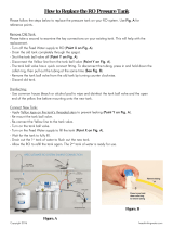
This is a good time to check the air pressure in your storage
tank. For instructions please see Page 9.
Step K – Follow Steps H through J in the Six Month System Mainte-
nance (Page 8) for startup directions.
9
Membrane Replacement
This reverse osmosis system contains a replaceable component (the
RO membrane) which is critical to the efficiency of the system.
Replacement of this reverse osmosis membrane should be with one
of identical specifications as defined by Watts to assure the same
efficiency and contaminant reduction performance.
Membranes have a life expectancy between 2 and 5 years, de-
pending on the incoming water conditions and the amount the
RO system is used. This reverse osmosis membrane is critical for
effective reduction of total dissolved solids (TDS). The product water
should be tested periodically to verify that the system is performing
satisfactorily.
Normally, a membrane would be replaced during a semiannual or
annual filter change. However, if at any time you notice a reduction
in water production or an unpleasant taste in the reverse osmosis
water, it could be time to replace the membrane. Watts recommends
replacing the membrane when TDS reduction falls below 75%.
Note: A water sample may be sent to Watts for a free diagno-
sis of your membrane performance. To send a water sample,
use two (2) clean containers and fill ½ cup of tap water in one
container and ½ cup of reverse osmosis water in 2nd container.
Clearly label each sample. Send the samples to the address
listed on the cover of this manual attention “Water Samples”.
Watts will test the water and mail or call you with the results.
Step A – Turn off the incoming water
supply to the RO by turning
the knob on the Adapt-A-
Valve™ clockwise until it
stops.
Step B – Open the RO Faucet and
allow water to drain from
the tank until it is completely
empty.
Removing the Membrane
Step A – Use a
5
8" wrench to remove the Green Tube fitting on the
left side of the horizontal membrane housing (end with one
elbow).
Step B – Remove the cap from the membrane housing by turning it
counterclockwise to loosen.
Note: A double sided wrench may
be purchased from Watts to aid with
loosening the cap / filter housings.
Step C – Remove membrane housing
from the holding clips. Using
a pair of pliers, grip the PVC
tube of the RO membrane and
pull firmly on the membrane to
remove from the housing and
discard.
Installing the Membrane
Step A – Lubricate the O-rings on the new membrane with a water
soluble lubricant such as KY Jelly ®. Insert the end with the
two black O-rings first into the
housing.
Step B – Once membrane has been
inserted into the housing you
must take your thumbs and
give a firm push to properly
seat the membrane. Replace
membrane housing cap and
tighten.
Step C – After replacing membrane
housing into clips, attach the
green tube to the elbow on
cap using
5
8" wrench.
Step D – Follow the Start Up Instruc-
tions on Page 7.
Procedure for Extended Non-Use
(More than 2 months)
Turn off the water supply by turning the knob on the Adapt-A-
Valve™ clockwise until it stops and open the RO faucet to empty
the storage tank (Save a few ounces of RO water). Once the storage
tank is empty, remove the membrane and place it in a sealed plastic
bag with the RO water saved earlier and store in your refrigerator.
For restart, reinstall membrane (See Page 9 for membrane installa-
tion procedure) and follow startup procedure on Page 7.
10
PROBLEM CAUSE SOLUTION
1. Low/slow production Excessive air pressure in tank Relieve pressure at schrader valve on tank (set to 7psi with
the tank empty)
Pump not operating Wiring connection broken (plug 110 AC wall, plug back in at
wall and/or reconnect the 24 VAC wire harness connectors)
Replace pump if needed
Fouled membrane Replace membrane
Plugged pre-filters Replace filters
Crimped tubing Check tubes to make sure they are not kinked
Angle stop or water line valve not fully opened Ensure valves are opened by turning valve handle counter-
clockwise until it stops
2. Milky colored water Air in the system Air in the system is a normal occurrence with initial start
up of the RO system. This milky look will disappear during
normal use within 1-2 weeks. If condition reoccurs after filter
changes, drain tank 1 to 2 times.
3. Faucet Dripping Needs adjustment see page 12
4. Pump short cycles Ball valve on tank closed Open the ball valve on the top of the tank
Blue tube blocked between the tank and RO system Faulty
pressure switch
Remove kinked/damaged section and replace if necessary
Call for technical support
5. Bowl leaks at the top after changing the filters Damaged/Dry O-ring Lubricate with water soluble lubricant or replace O-ring as
necessary (Do not use Vaseline® or other petroleum based
lubricants)
6. Pump constantly running Electrical fault Faucet left on Call for technical support. Close faucet and let tank fill for 2
to 3 hours.
Plugged pre-filters Replace filters
Troubleshooting
11
Parts List
COLD-WATER
SHUT-OFF VALVE
CARBON
PRE-FILTER
SEDIMENT
PRE-FILTER
TEE
FITTING
MEMBRANE HOUSING
STORAGE TANK
1/4” GREEN TUBE
FEED WATER
CARBON
POST-FILTER
FAUCET
PERMEATE
1/4” BLACK TUBE - BRINE
FLOW
RESTRICTOR
FLOW
ADAPT-A-VALVE
28
1
TO
KITCHEN
SINK
17
25
24
25
24
26
12
15
22
11
9
3
3
27 27
18
13 10
1/4” GREEN TUBE
1/4” BLUE TUBE
1/4” BLUE TUBE
18
18
21
PRESSURE
SWITCH
SELENOID
PUMP
HOT-WATER
SHUT-OFF VALVE
ADAPT-A-VALVE
1
TO
KITCHEN
SINK
1/4” BLUE TUBE
6
19
20
16
8
16
TRANSFORMER
7
23
CHECK
VALVE
4
14
2
2
5
30
1/4”-3/8” QC
ADAPTER
19
ITEM EDP DESCRIPTION
1 7300068 ADAPT-A-VALVE™
2 7300077
MOUNTING CLIP - DOUBLE - INLINE FILTER TO MEMBRANE
HOUSING
3 7300049 MOUNTING CLIP - MEMBRANE HOUSING
4 7300075 DOUBLE CHECK VALVE
5 7300015 PRESSURE SWITCH
6 7300001 BOOSTER PUMP - 1/4" QC
7 7300000 TRANSFORMER
8 7300076 SELENOID VALVE
9 7100203 TOP MOUNT FAUCET - CHROME
10 7100446 CARBON BLOCK FILTER
11 7100454 GAC POST-FILTER
12 710122 REVERSE OSMOSIS MEMBRANE
13 7100330 SEDIMENT FILTER
14 7300039 CONNECTOR - 1/4" M X 1/4" QC
15 7300029 CONNECTOR - 3/8"C X 1/4" M
ITEM EDP DESCRIPTION
16 7300034 ELBOW - 1/4" QC X 1/4" STEM
17 7300031 ELBOW - 1/4" C X 1/4" M
18 7300032 ELBOW - 1/4" C X 1/8" M
19 7300033 ELBOW - 1/4" QC X 1/8" M
20 7300036 BRASS HEX NIPPLE-BRASS - 1/4"M
21 7300073 TANK SHUT-OFF VALVE
22 7300038 TEE - MALE RUN 1/4" T X 1/4" M
23 7300025 FLOW RESTRICTOR (not shown)
24 7300044 FILTER HOUSING - BOWL - 10" - WHITE
25 7300081 FILTER HOUSING - LID - 1/4" PORTS
26 7300042 MEMBRANE HOUSING
27 7300060 O-RINGS FOR FILTER HOUSING
28 7100174 STORAGE TANK - 3 GAL WHITE
29 7300090 1/4" x 1/4" UNION
30 7300041 1/4" x 3/8" QC ADAPTOR
12
Arsenic Facts
Arsenic (As) is a naturally occurring contaminant found in many
ground waters. Arsenic in water has no color, taste or odor. It must
be measured by an arsenic test kit or lab test.
Public water utilities must have their water tested for arsenic. You
can obtain the results from your water utility contained with in your
consumer confidence report. If you have your own well, you will need
to have the water evaluated. The local health department or the state
environmental health agency can provide a list of test kits or certified
labs.
There are two forms of arsenic: pentavalent arsenic (also called As
(V), As (+5)) and trivalent arsenic (also called As (III), As (+3)). In well
water, arsenic may be pentavalent, trivalent, or a combination of
both. Although both forms of arsenic are potentially hazardous to
your health, trivalent arsenic is considered more harmful than pen-
tavalent arsenic.
RO systems are very effective at removing pentavalent arsenic. A free
chlorine residual will rapidly convert trivalent arsenic to pentavalent
arsenic. Other water treatment chemicals such as ozone and potas-
sium permanganate will also change trivalent arsenic to pentavalent
arsenic. A combined chlorine residual (also called chloramine) where
it does convert trivalent arsenic to pentavalent arsenic, may not con-
vert all the trivalent arsenic in to pentavalent arsenic. If you get your
water from a public water utility, contact the utility to find out if free
chlorine or combined chlorine is used in the water system.
This Watts reverse osmosis system is designed to remove up to 98%
of pentavalent arsenic. It will not convert trivalent arsenic to pen-
tavalent arsenic. Under laboratory standard testing conditions, this
system reduced 0.30 mg/L (ppm) pentavalent arsenic to under 0.010
mg/L (ppm) (the USEPA standard for drinking water). Actual perfor-
mance of the system may vary depending on specific water quality
conditions at the consumer’s installation. In addition to the indepen-
dent laboratory standard testing conditions Watts has conducted
additional field testing on our reverse osmosis units to determine
trivalent arsenic reduction capabilities. Based upon Watts field test-
ing, it has been determined that the RO units are capable of reducing
up to 67% of trivalent arsenic from the drinking water.
The RO membrane component of this Watts reverse osmosis system
must be maintained according to its recommended maintenance
cycle. Specific component identification and ordering information can
be found in the installation/operation manual maintenance section,
by phone at 1-800-224-1299 or online www.watts.com
13
DATE OF PURCHASE DATE OF INSTALL INSTALLED BY
DATE 1ST STAGE SEDIMENT
(6 MONTHS)
2ND STAGE CARBON
(6 MONTHS)
3RD STAGE CARBON
(6 MONTHS)
FINAL FILTER CARBON
(1 YEAR)
TFM MEMBRANE
(2 – 5 YEARS)
Notes:
Service Record
14
15
IOM-WQ-PWSYS-RO-STD4-ZRO 1145 EDP# 2915899 © 2011 Watts
USA: North Andover, MA • Tel. (800) 224-1299 www.watts.com
Canada: Burlington, ON Tel. (888) 208-8927 • www.wattscanada.ca
A Watts Water Technologies Company
LIMITED WARRANTY: Certain Watts Pure Water products come with a limited warranty from Watts Regulator Co. Other products may have no warranty or are covered by the original manufacturer’s
warranty only. For specific product warranty information, please visit www.watts.com or the published literature that comes with your product. Any remedies stated in such warranties are exclusive and
are the only remedies for breach of warranty. EXCEPT FOR THE APPLICABLE PRODUCT WARRANTY, IF ANY, WATTS MAKES NO OTHER WARRANTIES, EXPRESS OR IMPLIED. TO THE FULLEST EXTENT
PERMITTED BY APPLICABLE LAW, WATTS HEREBY SPECIFICALLY DISCLAIMS ALL OTHER WARRANTIES, EXPRESS OR IMPLIED, INCLUDING BUT NOT LIMITED TO THE IMPLIED WARRANTIES OF
MERCHANTABILITY AND FITNESS FOR A PARTICULAR PURPOSE, AND IN NO EVENT SHALL WATTS BE LIABLE, IN CONTRACT, TORT, STRICT LIABILITY OR UNDER ANY OTHER LEGAL THEORY, FOR
INCIDENTAL, INDIRECT, SPECIAL OR CONSEQUENTIAL DAMAGES, INCLUDING, WITHOUT LIMITATION, LOST PROFITS OR PROPERTY DAMAGE, REGARDLESS OF WHETHER IT WAS INFORMED ABOUT
THE POSSIBILITY OF SUCH DAMAGES.
  • Page 1 1
  • Page 2 2
  • Page 3 3
  • Page 4 4
  • Page 5 5
  • Page 6 6
  • Page 7 7
  • Page 8 8
  • Page 9 9
  • Page 10 10
  • Page 11 11
  • Page 12 12
  • Page 13 13
  • Page 14 14
  • Page 15 15
  • Page 16 16

Watts ZRO-4 Installation guide

Category
Sanitary ware
Type
Installation guide

Watts ZRO-4: Experience the Purity - Advanced Reverse Osmosis Technology for Your Home's Water Needs

The Watts ZRO-4 Reverse Osmosis System is a state-of-the-art water treatment solution designed to provide your household with an exceptional drinking water experience. Equipped with a 4-stage filtration process, this system effectively removes impurities, heavy metals, and contaminants, including arsenic, lead, and chlorine, leaving you with clean, refreshing water.

Ask a question and I''ll find the answer in the document

Finding information in a document is now easier with AI