Page is loading ...

Refer to enclosed warranty for operating parameters
to ensure proper use with your water supply.
Installation, Operation and
Maintenance Manual
3-Stage Reverse Osmosis System
Model: H2O-DWRO300
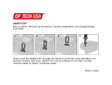
With Push-Button Filter Replacement
System tested and certified by WQA
against NSF/ANSI Standards 42 and NSF/
ANSI Standards 58 for the reduction of the
claims specified on the performance data
sheet, and NSF/ANSI Standard 372 for
Lead Free Compliance.
P/N 88005233
WARNING
!
Please read carefully before proceeding with
installation. Your failure to follow any attached
instructions or operating parameters may lead to
the product’s failure.
Keep this Manual for future reference.

Page 2
Overview
Thank you for your purchase of a state of the art Pure H2O
Reverse Osmosis (RO) water treatment system. Water quality
concerns are becoming more of a focus for the public. You
may have heard about contaminants in the drinking water
such as Arsenic, Chromium, Cryptosporidium or Giardia.
There may also be some local water issues such as high levels
of Lead and Copper. This Pure H2O water treatment system
has been designed to provide you with high quality drinking
water for years to come. The following is a brief overview of
the system.
Your Reverse Osmosis System:
Osmosis is the process of water passing through a semi-
permeable membrane in order to balance the concentration of
contaminants on each side of the membrane. A semi-permeable
membrane is a barrier that will pass only certain particles like
clean drinking water, but not other particles like arsenic and lead.
Reverse osmosis uses a semi-permeable membrane; however,
by applying pressure across the membrane, it concentrates
contaminants (like a strainer) on one side of the membrane,
producing crystal clear water on the other. This is why RO
systems produce both clean drinking water and rinse water that
is flushed from the system. This reverse osmosis system also
utilizes carbon block filtration technology, and can therefore
provide a higher quality drinking water than carbon filtration
systems alone.
Your system is a three stage Reverse Osmosis which is based
upon separate treatment segments within the one complete
water filtration system. These stages are as follows:
WARNING
!
Do not use with water that is microbiologically unsafe or of
unknown quality without adequate disinfection before or after
the system.
If you are unsure about installing your WATTS water filter, contact
a WATTS representative or consult a professional plumber.
Discard small parts remaining after the installation.
Failure to install the system correctly voids the warranty.
Handle all components of the system with care. Do not drop,
drag or turn components upside down.
Be sure the floor under the water filter system is clean, level
and strong enough to support the unit.
IMPORTANT
CAUTION
!
NOTICE
Stage 1 – Carbon Block Filter, recommended change
every 6 months.
The first stage contains a 5 micron carbon block filter. This helps
ensure that chlorine and other materials that cause bad taste
and odor are greatly reduced. It is independently tested and
verified to trap matter like dirt, silt, and rust.
Stage 2- Reverse Osmosis Membrane, recommended
change every 2-5 years.
The second stage is the heart of the reverse osmosis system,
the 50GPD (Gallons Per Day) RO membrane. This independently
tested and verified semi-permeable membrane will effectively
reduce TDS, Sodium and a wide range of contaminants such
as Chromium, Arsenic, Copper, and Lead, as well as Cysts,
such as Giardia and Cryptosporidium. Because the process of
extracting this high quality drinking water takes time, your RO
water treatment system is equipped with a storage tank.
Stage 3- Granular Activated Carbon filter, recommended
change every 12 months.
The third stage is a Granular activated carbon (GAC) filter.
This filter is used after the water storage tank, as a final
polishing filter to the product water. There is an average of
4 gallons of reject water for every 1 gallon of product water
produced. That is why the life of the GAC filter is extended to
12 months vs the 6 months Carbon block.
Note: Filter & Membrane life may vary based upon local water
conditions and/or use patterns.
System Maintenance
It is important to change filters at the recommended interval
indicated in this manual. Many contaminants are not detectable
by taste. In addition, other bad tastes and odors may become
apparent over time if filters are not replaced.
It is important to change out your filters at the recommended
intervals as indicated in this system manual. When replacing the
filter elements, pay special attention to any cleaning instructions.
Should you have any further questions please call our retail
customer service at (888) 321-0500.

Page 3
Operational Parameters
NOTICE
Installation must comply with state and local plumbing regulations.
Operating
Temperatures:
Maximum 100°F (37.8°C) Minimum 40°F
(4.4°C)
Operating Pressure: Maximum 100 psi (690 kPa) Minimum 35 psi
(341 kPa)
pH Parameters: Maximum 11 Minimum 2
Ir
on: Maximum 0.2 ppm
TDS
(Total Dissolved Solids)
< 1800 ppm
T
urbidity < 5 NTU
Hardness Maximum 10 Grains
Per Gallon *
Hardness: Recommended hardness not to exceed 10 grains per
gallon, or 170 parts per million.
* System will operate with hardness over 10 grains but the
membrane life may be shortened. Addition of a water
softener may lengthen the membrane life.
Water Pressure: The operating water pressure in your home
should be tested over a 24 hour period to attain the maximum
pressure. If the incoming water pressure is above 100 psi then a
water pressure regulator is required. A booster pump is needed
for incoming water pressure under 35psi.
NOTICE
Table of Contents
Overview ........................................2
Operational Parameters.............................3
Installation & Startup
Contents of Reverse Osmosis System..................4
Recommended Tools For Installation ...................4
Plumbing Diagram and Parts List......................5
Drill a Hole for the Reverse Osmosis Faucet..............6
How to use Quick Connect Fittings on Your RO System ....6
Faucet Installation .................................7
Adapt-a-Valve Installation ...........................8
Drain Saddle Installation ............................8
Drain Saddle Tube Connection .......................9
Tube Connections .................................9
Reverse Osmosis Module Mounting ..................10
Tank Ball Valve Installation ..........................10
Blue Tube Connection .............................10
Start up Instructions ..............................10
Maintenance & Troubleshooting
Membrane Replacement ..........................11
Changing The Filter Cartridges ......................11
Annual Sanitization ...............................12
Check Air Pressure in the Tank ......................13
Procedure for Extended Non-Use (More than 2 months) ...13
Performance Data Sheet ...........................14
Troubleshooting .................................15
Arsenic Fact Sheet ...............................15
Service Record ..................................16
Limited Warranty .................................18
Copper Tube: Reverse Osmosis water should not be run through
copper tube as the purity of the water will leach copper causing
an undesired taste in water and pin holes may form in the tube.
System is intended to be installed using the cold water supply only.
WARNING
!

Page 4
If any of the items are missing please contact retail customer
service at (888) 321-0500 prior to installing.
Contents of the Reverse Osmosis
(RO) System
Please make sure all of the items listed below are contained in the
box. If any of the items are missing please contact retail customer
service at (888) 321-0500 prior to installing.
• Tank
• Module - Carbon Block , Reverse Osmosis Membrane,
Granular Activated Carbon Filters (attached to filter head)
• Part bag - Water line tubing, Drain saddle, Adapt-a-valve
with brass adapters, drain saddle, tank ball valve, mounting
screws and Teflon™ tape
• Faucet with all assembly parts
Recommended Tools
For Installation
• 1 1/4" Diamond Tipped Hole Saw bit for faucet opening
(Counter Tops/Porcelain & Stainless Sinks)
• 1 1/4" adjustable wrench
• Phillips bit for electric drill
• 1/2" open end wrench
• Needle nose pliers
• 5/8" open end wrench
• Adjustable pliers
• Electric drill
• Sharp knife or tube cutter
• 1/8" diamond tip bit, pilot hole
• Phillips screw driver
• 1/4" drill bit for drain saddle hole

Page 5
Plumbing Diagram and Parts List
COLD WATER
ANGLE-STOP
SUPPLY
ADAPT
-A-
VALVE
TANK
GREEN-1/4" TUBE
FEED
AUTO-SHUT OFF
VALVE
DRAIN
SADDLE
BLUE 1/4" TUBE
TANK
BLUE 1/4" TUBE
FAUCET
RED 1/4" TUBE
BRINE
BLACK 3/8" TUBE
DRAIN
FAUCET
1
9
5
13
3
11
7
15
2
10
10
6
14
4
12
8
Parts List
Item Description
1 Filter Module
2 Automatic Shut off Valve
3 Storage Tank - 3 Gallons
4 Adapt-a-Valve
5 Faucet - Standard A/G Chrome
6 Tank Valve - 1/4" FPT x 1/4" C
7 Drain Saddle - 3/8 QC - Kit
8 Tank Stand
9 1/4" Green Tubing
10 1/4" Blue Tubing
11 3/8" Black Tubing - 3ft. X 1
12 1/4" Red Tubing
13 Carbon Block Filter (H2O-F12)
14 Reverse Osmosis Membrane Filter (H2O-F16)
15 Granular Activated Carbon Filter (H2O-F17)

Page 6
Step 1 - Determine desired
location for the
faucet on your sink
and place a piece of
masking tape over
where the hole is to
be drilled. Mark the
center of the hole on
the tape.
Step 2 - Using a variable
speed drill set on
the slowest speed,
drill a 1/8" pilot
hole with the 1/8th
in diamond drill
bit through both
porcelain and metal
casing of sink at the
marked center of
the desired location.
Use lubricating oil or liquid soap to keep the drill bit
cool (If drill bit gets hot it may cause the porcelain to
crack or chip).
Step 3 - Using a 1 1/4" diamond tip hole saw, proceed to drill
the large hole. Keep drill speed on the slowest speed
and use lubricating oil or liquid soap to keep the hole
saw cool during cutting.
Step 4 - After drilling, remove all sharp edges and make
sure the surroundings of the sink are cooled before
mounting the faucet.
NOTICE
NOTICE
Drill a Hole for the Reverse
Osmosis Faucet
For Marble and granite Counter-tops, we recommend contacting
a qualified contractor for drilling a hole in a marble and granite
counter-top.
Note: Most sinks are predrilled with 1½" or 1¼" diameter hole that
you can use for your Drinking Water faucet. (If you are already using
it for a sprayer or soap dispenser, see Step 1).
Porcelain sinks are extremely hard and can crack or chip easily.
Use extreme caution when drilling. Watts accepts no responsibility
for damage resulting from the installation of faucet. Diamond tip
bit recommended.
Cut the tube square. It is
essential that the outside
diameter be free of score
marks, and that burrs and
sharp edges be removed
before inserting into fitting.
Using Quick-Connect Fittings
Cutting
Make certain to push
the tubing completely
into the connector until
it comes into contact
with the internal tubing
stop. The collet (gripper) has stainless steel teeth which hold
the tube firmly in position while the O-ring provides a permanent
leak proof seal.
Pull on the tube to check that it is secure. The system must be
tested prior to leaving the site and/or before use.
Connecting
To disconnect, ensure the
system is depressurized
before removing the tube.
Push in collet squarely
against the face of the fitting. With the collet held in this position,
the tube can be removed. The fitting can then be reused.
Disconnecting
NOTICE
Or Punch a Hole for the Faucet in
a Stainless Steel Sink
If mounting faucet to a Stainless Steel Sink you will need a 1¼"
Hole Punch. The faucet opening should be centered between the
back splash and the edge of the sink, ideally on the same side as
the vertical drain pipe.
Step 1 - Drill a 1 1/4" pilot
hole. Use a 1 1/4"
Hole Punch and an
adjustable wrench
to punch the hole in
the sink.
Step 2 - The Faucet can
now be installed

Page 7
Step 1 - Remove water connector nut (Item 13) and blue
tubing (Item 14) from faucet.(Leave the plastic tube
insert and plastic delrin sleeve (Item 11 & 12) on the
blue tube).
Step 2 - Feed both the red (Item 3) and black tubing (Item 2)
through the pre-drilled hole in the sink/counter until
faucet is seated.
Step 3 - Under the sink - on to the threaded faucet stem (in
order ) first slide on the slotted metal washer (Item 6),
the plastic sleeve (Item 7) with the open end UP, the
plain washer (Item 8), the hex nut washer (Item 9) and
lastly secure with hex nut (Item 10).
Step 4 - Make sure the plastic delrin sleeve (Item 12) is on
the end of the blue tube; push the white plastic tube
insert (Item 11) into the end of blue tubing with the
delrin sleeve. Insert the blue tube (Item 14) into the
faucet stem and secure with water connector nut
with wrench (Item 13).
NOTICE
Secure the nut with a wrench but do not over tighten it.
Faucet Installation
4
STEP 2
Step A – Remove nut (Item 13) and blue tubing (Item 14) from fau-
cet. (Leave the nut and plastic delrin sleeve (Item 11 & 12)
on the blue tube).
Step B – Feed both the red and black tubing through the pre-drilled
hole in the sink/counter until faucet is seated.
Step C – Under the sink - on to the threaded faucet stem in order
first slide on the slotted washer (Item 6), the white spacer
with the open end UP (Item 7), the hex nut washer (Item 8),
the slotted washer (Item 9) and lastly secure with nut (Item
10).
Step D – Make sure the plastic delrin sleeve (Item 12) is on the end
of the blue tube; push the white plastic insert (Item 11) into
the end of blue tubing with the delrin sleeve. Insert the blue
tube (Item 14) into the faucet stem and secure with nut
(Item 13).
DO NOT overtighten nut.
1. Faucet
2. Black Drain Tube (3/8” Black)
3. Red Tube 1/4”
4. Escutcheon Plate
5. Full Circle Rubber Gasket
6. Slotted Metal Washer
7. Plastic Sleeve
8. Plain Washer
9. Hex Nut Washer
10. Hex Nut
11. Plastic Tube Insert
12. White Plastic Delrin Sleeve
13. Water Connector Nut
14. Blue Tube 1/4”
Parts List
1
2
3
4
5
6
7
8
9
10
11
12
13
14
NOTICE
1
9
3
11
5
12
7
14
2
10
4
6
13
8
Parts List
Item Description
1 Faucet
2 Black Drain Tube (3/8" Black)
3 Red Tube 1/4"
4 Escutcheon Plate
5 Full Circle Rubber Gasket
6 Slotted Metal Washer
7 Plastic Sleeve
8 Plain Washer
9 Hex Nut Washer
10 Hex Nut
11 Plastic Tube Insert
12 White Plastic Delrin Sleeve
13 Water Connector Nut
14 Blue Tube 1/4"

Page 8
If you have a garbage disposal, do not install the drain saddle near
it. Installation of the drain saddle must be either above the garbage
disposal, or if a second sink drain is available, install it above the
cross bar on the second drain. Installation of the drain saddle near
a garbage disposal may cause the drain line to plug.
Drain Saddle fits standard 1 ¼" – 1 ½" drain pipes
Drain Saddle Installation
CAUTION
!
1 Semicircle bracket with opening 2 Screws
1 Foam gasket 2 Nuts for screws
1 Semicircle bracket
Step 1 - Gather the pieces of the drain saddle
Step 1 - Turn off the cold water supply to the faucet by turning
the angle stop valve completely off.
Step 2 - Open cold water sink faucet to relieve pressure.
Step 3 - Disconnect the Faucet Line from the Cold water
supply.
Step 4 - Choose the configuration that fits your plumbing
needs and attach Adapt-a-Valve
TM
as instructed and
illustrated below.
Option 1: 3/8" Configuration (diagram to left)
a. Insert the White Rubber Washer (C) into the opening of Brass
Adapter with no washer (D)
b. Attach the female end of the Brass Adapter / White rubber
washer assembly (C&D) into the male end of the cold water
supply
c. Attach the female end of the plastic Adapt-a-Valve & Black
Collet (B) to the Brass Adapter/White Rubber Washer
Assembly (C&D)
d. Attach the female end of the Brass Adapter (A) to the male
end of the Plastic Adapt-a-Valve and black Collet (B)
e. Attach the faucet line to the Brass adapter (A)
Option 2: 1/2" Configuration (diagram to left)
a. Attach the Male end of Adapt-a-Valve and Black Collet (B)
into the Female end of the cold water supply
b. Attach the Male End of the Faucet Connection into the
Female end of the Adapt-a-Valve and Black Collet (B)
Parts List for Adapt-a-Valve
Item Description
A Brass Adapter with black washer
B Plastic Adapt-a-Valve & black collet
C White Rubber Washer
D Brass Adapter with no washer
NOTICE
NOTICE
NOTICE
Adapt-a-Valve Installation
Water supply line to the system must be from the cold water supply
line only. Hot water will severely damage your system.
Make sure that the black collet is installed into the 1/4" opening
on the Adapt-a-Valve. Don’t forget to install the white compression
washer with the 3/8" configuration. The Brass Adapters do not need
to be tightened with a wrench, only finger tight.
Do not use Teflon tape with the Adapt-a-Valve™.
D
B
Line from
Cold Water
Supply
Faucet
Connection
Faucet Line
Cold
Water
Supply
C
B
A
D
B
Line from
Cold Water
Supply
Faucet
Connection
Faucet Line
Cold
Water
Supply
C
B
A
For 1/2" Configuration
(Option 2)
For 3/8" Configuration
(Option 1)

Page 9
Rear View of 3 stage Reverse
Osmosis System
Blue Tube Connection (From FAUCET To The
Reverse Osmosis (RO) Module)
Red Tube Connection (From FAUCET To The
Reverse Osmosis (RO) Module)
Do not over tighten the screws. It may crack the drain saddle.
CAUTION
!
Step 2 - The small square black
foam gasket with a circle
cut out of the middle
must be applied to the
inside of the drain saddle.
Remove sticky tape
backing and stick to the
drain saddle as shown.
Step 3 - The drain saddle must
be installed at least 1 ½"
above the nut of the P-Trap
elbow or cross bar from the
garbage disposal to insure
proper drainage. Using the
1/4" drill bit, drill into the
drain pipe at best available
location as specified above,
for drain saddle installation.
Take extreme caution to
only drill through one side of
the drain pipe.
Step 4 - Assemble the drain saddle around the drain pipe
and align drain saddle fitting opening with the hole
drilled in the previous step - you may use a small
screwdriver to feed through the drain saddle into the
drain pipe to aid with the alignment. Using a Phillips
screw driver tighten the drain saddle bolts evenly and
securely on both sides.
Step 5 - Measure the 3/8" black
tube from faucet to the
drain saddle on the drain
pipe and make a straight
cut to the correct length.
Step 6 - Connect the black tube to
the open quick connect
fitting on the drain saddle
by pushing the tube all the way to the tube stop.
Step 1 - Locate the 1/4" BLUE tube from the RO faucet.
Position the module as indicated in the “rear view”
picture. Insert the Blue Faucet tube into the 1/4”
quick connect fitting (position A) located behind the
GAC Filter head making sure the tube is pushed in all
the way to the tube stop.
See Diagram Above.
Step 1 - Locate the 1/4" RED tube attached to the RO faucet.
Insert the end of the red tube into the 1/4” quick
connect fitting ( position B) located behind the RO
Membrane head making sure the tube is pushed in
all the way to the tube stop.
NOTICE
The black 3/8" drain tube must be as SHORT and STRAIGHT as
possible to the drain saddle, making a downward slope from faucet
to drain saddle to allow for proper drainage. This is a gravity fed
line and if there is any bend or dip in the tube, the rinse water will
not flow into the drain properly. Water may back up and come out
the air gap hole in the back of the faucet.
CARBON BLOCK
H2O-F12
RO MEMBRANE
H2O-F16
GAC
H2O-F17
MOUNTING HOLES
GREEN TUBE-FEED
BLUE TUBE-TANK
RED TUBE-DRAIN
BLUE TUBE-FAUCET
A
B
C
D

Page 10
Step 1 - Turn on the incoming
cold water at the angle
stop valve and the
Adapt-a-Valve. Check
the system for leaks
and tighten any fittings
as necessary. (Check
frequently over the next 24 hours to ensure no leaks
are present).
Step 2 - Open the RO faucet and leave it open until water
begins to trickle out (this may take a few minutes and
the water will come out slowly).
Step 3 -
Close the RO faucet allowing the storage tank to fill with
water. It may take 3 to 6 hours to fill the tank completely
depending on the production capability of the
membrane, local water temperature and water pressure.
You will know that the water tank is filled when you no
longer hear the water flow sound from the tank.
Green Tube Connection
Step 1
- Insert the open end of
the green 1/4" tube
from AUTO-SHUT OFF
VALVE into the Black
Collet of the Adapt-
a-Valve making sure
the tube is pushed in
all the way to the tube
stop. See Diagram on
the right
Reverse Osmosis Module Mounting
Step 1
- Determine best
location for the RO
module to be mounted
to allow for future
system maintenance.
Recommended best
location is 6" away
from the cabinet side
walls, and 10" from the
bottom of the cabinet for ease of installation and filter
change. The parts bag has 2 self tapping screws.
Using an electric drill with a Phillips bit, secure the
screws to the cabinet wall at locations that align with
the hole spacing on the module bracket.
Tank Ball Valve Installation
Step 1
- Teflon
™
tape must be
applied in a clockwise
direction. Wrap (7 to 12
turns) around the male
pipe threads (MPT) on
the stainless steel fitting
on top of the tank.
Step 2 - Thread the
compression tank
ball valve (supplied in
the parts bag) onto
the stainless steel
connector on the tank.
NOTICE
NOTICE
Set the blue Tank valve knob in-line with the blue tube, this is the
“open” position.
If you have connected your RO system to a refrigerator / ice maker,
make sure the ice maker is off (do not allow water to flow to the
ice maker) until flushing (Step 4) is complete and the tank has
been allowed to fill completely. Connection from the RO to the ice
maker system should have an in-line valve installed before the ice
maker so it can easily be closed to prevent water flowing to the ice
maker during start up and periodic maintenance. Your storage tank
must be allowed to fill up fully in order for the ice maker system to
work properly.
Green Tube
Adapt-a-Valve
Start up Instructions
Congratulations! You have completed the
installation of your new water filtration system.
Please Follow the Startup Instructions.
ON
Step 4
- After the storage tank has filled open the RO Faucet
to flush the tank completely. You will know that the
tank is empty when the flow rate from the RO faucet
is down to a trickle. Repeat this step two more times.
The fourth tank can be used for drinking.
The flushing process should take about a day to complete.
Blue Tube Connection (From The Tank to
Shut off Valve and from Shut off Valve to the
Reverse Osmosis Module)
Step 1
- Position tank in desired location. Stand it upright
or lay it on its side (using the black plastic stand).
Measure the blue tube (marked “TANK”) from the
RO module to the tank and cut it to length leaving a
straight, square edge.
Step 2 - To the Blue tank tube (from position C) apply the
compression fitting to the cut edge side of the
tube. Make sure the
compression fitting
threaded opening is
facing the cut end of
the tube as shown in
the figure.
Step 3 - Insert the square edge
cut end of the blue
tube into the Tank
Valve opening. Using
clockwise rotation,
tighten the compression
fitting to the Tank Valve securing the tube in place.
See Diagram to right.

Page 11
NOTICE
NOTICE
Flushing of the tank 3 times is only necessary during the initial
startup and after replacing the reverse osmosis membrane.
Flush first tank after completing the annual maintenance.
Step 1 - Place a towel under the RO module to catch any
excess water that may drip out from the filters during
the changeover.
Step 2 - To remove a filter cartridge: Push & hold the button
on the valve head above the filter. Twist filter
counter-clockwise for about 45 degree while pulling
downward (from the head). Release button and
discard old filter.
Step 3 - To install a filter cartridge: Remove the seal cap and
insert the cartridge into the filter head, push upward
and twist the filter clock-wise for about 45 degree
until you hear an audible “click” (the button does not
need to be pressed to install new filters)
Changing The Filter Cartridges
Your RO module is equipped with valve heads which will
automatically turn off the water supply to each filter when the
filter is released, thus you do not need to turn off the incoming
water supply at the Adapt-a-Valve. The RO faucet must be
off when filters are replaced. To make the removal of the filter
cartridges easier, the heads & cartridges may be swiveled up to
90 degrees as shown in the pictures to the right.
To buy replacement part(s) please visit the retail store or their
website or contact Watts retail customer service at
(888) 321-0500
This reverse osmosis system contains a replaceable component
(the RO membrane) which is critical to the efficiency of the system.
Replacement of this reverse osmosis membrane should be with
H2O-F16 as defined by Pure H2O to assure the same efficiency
and contaminant reduction performance.
Annual Maintenance -
(Sanitization Recommended See page - 12)
• Carbon Block Filter ...................... H2O-F12 (P/N # 88005217)
Capacity- 6 months / 2000 Gallons
• Granular Activated Carbon Filter
... H2O-H17 (P/N # 88005219)
Capacity- 12 months / 2000 Gallons
• Carbon Block Filter .....................H2O-F12 (PN # 88005217)
Capacity- 6 months / 2000 Gallons
• Reverse Osmosis Membrane Filter ...H2O-F16 (P/N 88005218)
Capacity- 2-5 years
Replace:Replace:
Replace:
Replace:
6 Month System Maintenance
TIP: This is a good time to check the air pressure in your storage
tank. For instructions please see page 13.
Membrane Replacement (2 - 5 Years)
Membranes have a life expectancy between 2 and 5 years,
depending on the incoming water conditions and the amount the RO
system is used. This reverse osmosis membrane is critical for effective
reduction of total dissolved solids (TDS). The product water should be
tested periodically to verify that the system is performing satisfactorily.
Normally, a membrane would be replaced during a semiannual or
annual filter change. However, if at any time you notice a reduction in
water production or an unpleasant taste in the reverse osmosis water,
it could be time to replace the membrane. Pure H2O recommends
replacing the membrane when TDS reduction falls below 75%.
A water sample may be sent to Pure H2O for a free diagnosis of
your membranes performance. To send a water sample, use 2 clean
containers and fill 1/2 cup of tap water in one container and 1/2 cup
of RO water in 2nd container. Clearly label each sample. Send the
samples to the address listed on the cover of this manual attention
“Water Samples”. Pure H2O will test the water and mail or call you
with the results.
Step 3-1
Step 3-3
Step 2
Step 3-2
Product Registration
To Register your product, please visit www.watts.com/pureh2o
and select “Register Now”. Watts is concerned for the safety of
your personal information. WATTS collects personal information
when you register with Watts. This information is stored in our
data base and we do not rent, sell, or share personal information
with other people or nonaffiliated companies. We will send you
certain types of communications such as direct mail, email, or
by telephone relating to our products or products that you have
purchased only with your prior permission. We limit access to
your personal information to those employees who will directly
provide you with services or products in order to do their jobs.
See our privacy policy at - http://www.watts.com/privacy.asp
See Terms of Use at - http://www.watts.com/terms.asp
Tubing not shown in above pictures. Do not remove the tubing
while changing the filter
NOTICE

Page 12
Point Hose
Ends Away
From Face
Dosing Syringe
With No Needle
DANGER
!
IF BLEACH GETS IN EYES: Hold eye open and rinse
slowly and gently with water for 15 - 20 minutes.
Remove contact lenses if present, after the first 5
minutes, then continue rinsing eye. Call a poison
control center or doctor for treatment advice.
NOTICE
NOTICE
Do not change your Granular Activated Carbon filter until the
sanitization has been completed. The Carbon Block and Reverse
Osmosis Membrane can be changed before the sanitization.
If you have connected your RO system to a refrigerator/ice maker,
make sure the connection has been turned off. Do not re-open the
connection until the sanitization process is complete.
Step 1 - Turn off the water supply to your RO system at the
Adapt-a-Valve and open the RO faucet to drain the
storage tank.
Step 2 - Locate the tube that runs between your filter module
and the storage tank and disconnect at both ends.
Step 3 - Drain any remaining water in the tube.
Step 4 - Hold both ends of the tube together with the ends
pointed away from your face. Using a dosing syringe
(see figure) slowly insert 1 teaspoon (5 mL) of
common household bleach into the tube.
Step 5 - While covering one end of the tube with your finger,
insert the other into the tank. Then insert the open
end into the filter module.
Step 6 - Turn the incoming water back on and let the system
fill for approximately 3 to 6 hours.
Step 7 - Turn off the incoming water and let the system sit for
1 minute.
Step 8 - Drain the system completely and then follow the
startup procedure - filling then draining three full
tanks of water.
Step 9 - Replace the Granular Activated Carbon filter once
complete.
Annual Sanitization
WARNING
!
Do not use needle syringe

Page 13
To Restart System:
Step 1
- Install the filters as shown in the 'Changing The Filter
Cartridges' section on page 11.
Step 2 - Turn on water supply to the system at the Adapt-a-
Valve. (Check frequently over the next 24 hours to
ensure no leaks are present).
Step 3 - Open the RO faucet and leave it open until water
begins to trickle out (it will come out slowly).
Step 4 - Close the RO faucet allowing the storage tank to fill
with water. It may take 3 to 6 hours to fill the tank
completely depending on the production capability
of the membrane, local water temperature and water
pressure.
Step 5 - After the Tank has filled, open the RO Faucet to flush
the tank completely. You will know that the tank
is empty when the flow rate from the RO faucet is
down to a trickle. The second tank can be used for
drinking.
NOTICE
NOTICE
NOTICE
Check air pressure only when tank is empty of water!
DO NOT FREEZE.
If you have connected your RO system to a refrigerator / ice maker,
make sure the ice maker is off (do not allow water to flow to the ice
maker) until the tank has been allowed to completely fill.
Step 1 - Turn off the incoming
water supply to the
RO.
Step 2 - Open the RO Faucet
and allow water to
drain from the tank
until it is completely
empty.
TIP:
When water from the RO faucet slows to a trickle, with the faucet still
in the open position, you may add air to the tank to purge any left
over water, this will ensure that the tank is completely empty.
Step 3 - Once all water in the tank is purged, check air
pressure using an air pressure gauge, it should read
between 5 - 7 PSI. (Digital air pressure gauge is
recommended)
Step 4 - Follow startup procedure on page 10.
Check air pressure in the storage tank when you notice a
decrease in available water from the RO system. Air can
be added with a bicycle pump using the schrader valve
that is located on the lower side of the tank behind the
blue plastic cap.
Turn off the water supply to your RO system at the Adapt-a-
Valve and open the RO faucet to drain the storage tank. Once
the storage tank is empty, remove all filter cartridges as shown
in the 'Changing The Filter Cartridges' section on page 11 (order
not important), place them into a sealed plastic bag and store in
your refrigerator.
Check Air Pressure in the Tank
Procedure for Extended Non-Use
(More than 2 months)

Page 14
Performance Data Sheet
Pure H2O
-In U.S.-Watts Regulator Co., N. Andover, MA 01845 (Watts.com)
-In Canada-Watts, Water Technologies (Canada), Inc. Toronto, ON M5J3G6 (Watts.ca)
3-Stage Reverse Osmosis System - H2O-DWRO300
Recommended Replacement Parts and Change Interval
Note: Depending on incoming feed water conditions replacement time frame may vary.
Description Model / Part Number Change Time Frame
Carbon Block Filter H2O-F12 / 88005217 6 Months or 2000 Gallons
Reverse Osmosis
Membrane
H2O-F16 / 88005218 2 to 5 years
Granular Activated Carbon
Filter
H2O-F17 / 88005219 12 Months or 2000 Gallons
Avg. In. (mg/L) Avg. Eff. (mg/L) % Reduction pH Pressure Max Eff. mg/L
Inf. challenge
concentration mg/L
Max Allowable
concentration mg/L
Arsenic (Pentavalent) .310 0.001 99.6% 7.24 50psi 0.002 0.30±10% 0.010 mg/L
Barium Reduction 9.2 0.08 99.0% 7.64 50psi 0.12 10.0±10% 2.0
Cadmium Reduction 0.031 0.0004 98.0% 7.49 50psi 0.0008 0.03±10% 0005
Chlorine 2.05 0.03 97% 7.0 - 8.0 N/A 2.4 2.0 mg/L ± 10% 2.2
Chromium (Hexavalent 0.30 0.002 99.0% 7.24 50psi 0.004 0.03±10% 0.1
Chromium (Trivalent) 0.30 0.001 99.0% 7.64 50psi 0.002 0.03±10% 0.1
Copper Reduction 3.2 0.02 99.0% 7.40 50psi 0.04 3.0±10% 1.3
Cysts 92,000/ml 3/ml 99.99% 7.44 50psi 18 minimum 50,000/mL N/A
Fluoride Reduction 8.7 0.19 97.0% 7.24 50psi 0.3 8.0±10% 1.5
Lead Reduction 0.15 0.002 98.8% 7.39 50psi 0.005 0.15±10% 0.0107
Radium 226/228 25pCi/L 5pCi/L 80.0% 7.24 50psi 5pCi/L 25pCiL±10% 5pCiL
Selenium 94.85 <0.2 97.0% 7.24 50psi <0.2 0.10±10% 0.05
TDS 770 35 95.0% 7.28 50psi 26.0 750±40mg/L 187
Turbidity 11.3 0.1 99.0% 7.43 50psi 0-1 11±1mg/L 0.5NTU
Turbidity 11.3 0.1 99.0% 7.43 50psi 0-1 11±1mg/L 0.5NTU
Recovery - 22% Daily Production Rate - 20.5 GPD Efficiency - 10.5%
GENERAL USE CONDITIONS
1. System to be used with municipal or well water sources
treated and tested on regular basis to insure bacteriological
safe quality. DO NOT use with water that is microbiologically
unsafe or unknown quality without adequate disinfection
before and after the system. Systems certified for cyst
reduction may be used on disinfected water that may contain
filterable cysts.
2: Operating Temperature: Maximum: 100°F (37.7°C) Minimum
40° F (4.4° C)
3: Operating Water Pressure: Maximum 100-psi (690 kPa)
Minimum: 35 psi (341 kPa)
4. pH 2 to 11
5. Maximum Iron present in incoming water supply must be less
than 0.2 ppm.
6. Hardness of more than 10 grains per gallon (170 ppm) may
reduce RO membrane life expectancy.
7. Recommend TDS (Total Dissolved Solids) not to exceed
1800 ppm.
This system has been tested according to NSF/ANSI 58 for reduction of the substances listed below. The concentration of the indicated
substances in water entering the system was reduced to a concentration less than or equal to the permissible limit for water leaving the
system as specified in NSF/ANSI 58 and 42. This system has been tested for the treatment of water containing pentavalent arsenic (also
known as As (V), As (+5), or arsenate) at concentrations of 0.30 mg/L or less. This system reduces pentavalent arsenic, but may not
remove other forms of arsenic. This system is to be used on water supplies containing a detectable free chlorine residual at the system
inlet or on water supplies that have been demonstrated to contain only pentavalent arsenic. Treatment with chloramine (combined
chlorine) is not sufficient to ensure complete conversion of trivalent arsenic to pentavalent arsenic, Please see the Arsenic Facts section
of the Performance Data Sheet for further information.
While testing was performed under standard laboratory conditions, actual performance may vary. Depending on water chemistry, water
temperature, and water pressure the systems production and performance will vary. Efficiency rating means the percentage of the
influent water to the system that is available to the user as reverse osmosis treated water under operating conditions that approximate
typical daily usage. Recovery rating means the percentage of the influent water to the membrane portion of the system that is available
to the user as reverse osmosis treated water when the system is operated without a storage tank or when the storage tank is bypassed.
There is an average of 4 gallons of reject water for every 1 gallon of product water produced.

Page 15
Troubleshooting
Arsenic Fact Sheet
Problem Cause Solution
1. Low/Slow Production • Low Water Pressure
• Crimps in tubing
• Clogged Carbon Block Filter
• Fouled Reverse Osmosis Membrane
• Assure a minimum of 35 psi incoming water pressure. Watts sells a booster pump
if home water pressure is low. Make sure water supply is turned on and feed water
valve is all the way open.
• Check tubing and straighten or replace as necessary.
• Replace Carbon Block Filter.
• Replace membrane.
2. Milky colored Water • Air in system • Air in the system is a normal occurrence with initial start up of the RO system. This
milky look will disappear during normal use within 1-2 weeks. If condition reoccurs
after filter change, drain tank 1 to 2 times.
3. Water constantly running, unit will
not shut off
• Low water pressure
• Crimp in supply tube
• High water pressure
• High pressure in Tank
• Low Pressure in Tank
• See #1 Above
• Check tubing and straighten or repair as necessary
• Check incoming water pressure to make sure it does not exceed 100 psi. A pressure
regulator will be required (not included with the system).
• Empty storage tank of water. Set tank air pressure between 5-7 psi. See previous
page.
• Use a Digital Air Gauge for best results. The empty tank pressure should be 5-7 psi.
See page 13.
4. Water from faucet vent hole or noise
from drain
• Crimp or restriction in drain line
• Drain tube clogged
• Check tubing and straighten or repair as necessary. Straighten all drain lines. Clear
blockage. Cut off any excess tubing from the drain line and reinstall the drain line per
the instructions. Check for leaks
• Caused from dishwasher or garbage disposal. Disconnect the 3/8" black line at the
drain, clean the 3/8" black line out with a wire, then reconnect . Check for leaks.
blowing air through the line will not always remove the clog.
5. Small amount of water in storage
tank
• System starting up
• Low water pressure
• Too much air in tank
• Normally it takes 3 hours to fill tank. Note: low incoming water pressure and/or
temperature can drastically reduce production rate.
• See #1 above.
• Tank air pressure should be 5-7 psi when empty of water. If below 5 psi add air or
bleed if above 7 psi. Check only when tank is empty of water. See previous page.
6. Low water flow from faucet • Check air pressure in tank • Use a Digital Air Gauge for best results. The empty tank pressure should be 5-7 psi.
See page 13.
Arsenic (As) is a naturally occurring contaminant found in many ground waters. Arsenic in water has no color, taste or odor. It must be
measured by an arsenic test kit or lab test.
Public water utilities must have their water tested for arsenic. You can obtain the results from your water utility contained within your
consumer confidence report. If you have your own well, you will need to have the water evaluated. The local health department or the
state environmental health agency can provide a list of test kits or certified labs.
There are two forms of arsenic: pentavalent arsenic (also called As (V), As (+5)) and trivalent arsenic (also called As (III), As (+3)). In well
water, arsenic may be pentavalent, trivalent, or a combination of both. Although both forms of arsenic are potentially hazardous to your
health, trivalent arsenic is considered more harmful than pentavalent arsenic.
RO systems are very effective at removing pentavalent arsenic. A free chlorine residual will rapidly convert trivalent arsenic to pentavalent
arsenic. Other water treatment chemicals such as ozone and potassium permanganate will also change trivalent arsenic to pentavalent
arsenic. A combined chlorine residual (also called chloramine) where it does convert trivalent arsenic to pentavalent arsenic, may not
convert all the trivalent arsenic in to pentavalent arsenic. If you get your water from a public water utility, contact the utility to find out if
free chlorine or combined chlorine is used in the water system.
This Pure H2O reverse osmosis system is designed to remove up to 98% of pentavalent arsenic. It will not convert trivalent arsenic to
pentavalent arsenic. Under laboratory standard testing conditions, this system reduced 0.30 mg/L (ppm) pentavalent arsenic to under
0.010 mg/L (ppm) (the USEPA standard for drinking water). Actual performance of the system may vary depending on specific water
quality conditions at the consumer’s installation. In addition to the independent laboratory standard testing conditions Pure H2O has
conducted additional field testing on our reverse osmosis units to determine trivalent arsenic reduction capabilities. Based upon Pure
H2O field testing, it has been determined that the RO units are capable of reducing up to 67% of trivalent arsenic from the drinking
water.
This reverse osmosis system contains a replaceable component critical to the efficiency of the system. Replacement of the reverse
osmosis component should be with one of identical specifications, as defined by the manufacturer, to ensure the same efficiency and
contaminant reduction performance. Specific component identification and ordering information can be found in the maintenance
section of this manual, by phone at (888) 321-0500.

Page 16
Service Record
Date of Purchase:__________ Date of Install:___________ Installed by:_____________
NOTES:
Model Number:__________ Serial Number:___________
Date Carbon Block Filter
H2O-F12
(6 months)
Reverse Osmosis Membrane
H2O-F16
(2-5 years)
Granular Activated Carbon Filter
H2O-F17
(12 months)

IOM-WQ-H2O-DWRO300 1917 EDP# 88005433 © 2019 Watts
USA: Tel: (978) 689-6066 • Fax: (978) 975-8350 • Watts.com
Canada: Tel: (905) 332-4090 • Fax: (905) 332-7068 • Watts.ca
Latin America Tel: (52) 81-1001-8800 • Watts.com
Limited Warranty
What Your Warranty Covers:
Watts warrants your H2O-DWRO300 (excluding replaceable filters) to be free from defects in material and workmanship under normal
usage for a period of one year from the date of original purchase. If any part of this system is found to be defective within the warranty
period, return the system after obtaining a return authorization from Watts (see below), and Watts will repair, or at Watts’ option, replace
the system at no charge.
How to Obtain Warranty Service:
To obtain warranty service, call 888-321-0500 for a return authorization number. Then, ship your system to our factory, freight and
insurance prepaid, with proof of the date of original purchase. Please include a note stating the warranty problem. Watts will repair, or
at Watts’ option, replace the system and ship it back to you at no charge.
What this Warranty Does Not Cover:
This warranty does not cover defects resulting from improper installation (installation contrary to Watts printed instructions), abuse,
misuse, misapplication, improper maintenance, neglect, alteration, accidents, casualties, fire, flood, freezing, environmental factors,
water pressure spikes, adverse water conditions or other events or conditions beyond Watts’ control.
This warranty will be void if defects occur due to failure to observe the following conditions:
1. The system must be hooked up to a potable municipal or well cold water supply.
2. The pH of the water must not be lower than 2 or higher than 11.
3. The incoming water pressure must be between 35 and 100 pounds per square inch.
4. Incoming water to the system cannot exceed 100 degrees F (38 degrees C.)
5. The hardness of the water should not exceed 10 grains per gallon, or 170 ppm.
6. Maximum incoming iron must be less than 0.2 ppm.
7. Incoming TDS/Total Dissolved Solids not to exceed 1800 ppm. This warranty does not cover any equipment that is relocated from
the site of its original installation.
This warranty does not cover any charges incurred due to professional installation.
Other Conditions:
If Watts chooses to replace the system, Watts may replace it with reconditioned equipment. Parts used in repairing or replacing the
system will be warranted for 90 days from the date the system is returned to you or for the remainder of the system’s original warranty
period, whichever is longer. This warranty is not assignable or transferable.
Limitations and Exclusions:
THE WARRANTY SET FORTH HEREIN IS GIVEN EXPRESSLY AND IS THE ONLY WARRANTY GIVEN BY WATTS WITH RESPECT TO
THE SYSTEM. WATTS MAKES NO OTHER WARRANTIES, EXPRESS OR IMPLIED. WATTS HEREBY SPECIFICALLY DISCLAIMS
ALL OTHER WARRANTIES, EXPRESS OR IMPLIED, INCLUDING THE IMPLIED WARRANTIES OF MERCHANTABILITY OR FITNESS
FOR A PARTICULAR PURPOSE. The warranty remedy described above shall constitute the sole and exclusive remedy for breach of
warranty, and Watts shall not be responsible for an incidental or consequential damages, including travel expense, telephone charges,
loss of revenue or profits, loss of time, inconvenience, loss of use of the equipment, or loss or damage caused by this system and its
failure to function properly. This warranty sets forth all of Watts responsibilities regarding this system.
Your Rights Under State Law:
Some states do not allow the exclusion or limitation of incidental or consequential damages and some states do not allow limitations
on how long implied warranties may last. Therefore, the above limitations or exclusions may not apply to you. This warranty gives
you specific legal rights and you may also have other rights, which vary from state to state. SO FAR AS IS CONSISTENT WITH
APPLICABLE STATE LAW, ANY IMPLIED WARRANTIES THAT MAY NOT BE DISCLAIMED, INCLUDING IMPLIED WARRANTIES OF
MERCHANTABILITY OR FITNESS FOR A PARTICULAR PURPOSE ARE LIMITED IN DURATION TO ONE YEAR FROM THE DATE OF
ORIGINAL PURCHASE.

Page 25
Paso 1 - Retire la tuerca conectora de agua (elemento 13)
y tubo azul (elemento 14) del grifo. (Deje el inserto
de plástico para tubo y manguito Delrin de plástico
[elemento 11 y 12] en el tubo azul).
Paso 2 - Coloque los tubos rojo (elemento 3) y negro
(elemento 2) en el orificio previamente perforado en
el lavabo/mostrador hasta que el grifo se asiente.
Paso 3 - Debajo del lavabo - sobre el vástago roscado (en
orden): primero deslice la arandela ranurada de
metal (elemento 6), el manguito plástica (elemento
7) con el extremo abierto hacia ARRIBA, la arandela
simple (elemento 8), la arandela de la tuerca
hexagonal (elemento 9), y por último asegure con la
tuerca hexagonal (elemento 10).
Paso 4 - Asegúrese de que el manguito Delrin de plástico
(elemento 12) esté en el extremo del tubo azul;
empuje el inserto de plástico blanco para tubo
(elemento 11) en el extremo del tubo azul con el
manguito Delrin. Inserte el tubo azul (elemento
14) en el vástago del grifo y fíjelo con la tuerca del
conector de agua con la llave (elemento 13).
AVISO
Asegure la tuerca con una llave, pero no la apriete demasiado.
Instalación del grifo
4
STEP 2
Step A – Remove nut (Item 13) and blue tubing (Item 14) from fau-
cet. (Leave the nut and plastic delrin sleeve (Item 11 & 12)
on the blue tube).
Step B – Feed both the red and black tubing through the pre-drilled
hole in the sink/counter until faucet is seated.
Step C – Under the sink - on to the threaded faucet stem in order
first slide on the slotted washer (Item 6), the white spacer
with the open end UP (Item 7), the hex nut washer (Item 8),
the slotted washer (Item 9) and lastly secure with nut (Item
10).
Step D – Make sure the plastic delrin sleeve (Item 12) is on the end
of the blue tube; push the white plastic insert (Item 11) into
the end of blue tubing with the delrin sleeve. Insert the blue
tube (Item 14) into the faucet stem and secure with nut
(Item 13).
DO NOT overtighten nut.
1. Faucet
2. Black Drain Tube (3/8” Black)
3. Red Tube 1/4”
4. Escutcheon Plate
5. Full Circle Rubber Gasket
6. Slotted Metal Washer
7. Plastic Sleeve
8. Plain Washer
9. Hex Nut Washer
10. Hex Nut
11. Plastic Tube Insert
12. White Plastic Delrin Sleeve
13. Water Connector Nut
14. Blue Tube 1/4”
Parts List
1
2
3
4
5
6
7
8
9
10
11
12
13
14
NOTICE
1
9
3
11
5
12
7
14
2
10
4
6
13
8
Lista de piezas
Elemento Descripción
1 Grifo
2 Tubo de drenaje de color negro (de 3/8" color negro)
3 Tubo rojo de 1/4"
4 Planchuela
5 Junta circular de goma
6 Arandela ranurada de metal
7 Manguito de plástico
8 Arandela simple
9 Arandela para tuerca hexagonal
10 Tuerca hexagonal
11 Inserto de plástico para tubo
12 Manguito Delrin de plástico blanco
13 Tuerca conectora de agua
14 Tubo azul de 1/4"

Page 32
Performance Data Sheet
Pure H2O
-In U.S.-Watts Regulator Co., N. Andover, MA 01845 (Watts.com)
-In Canada-Watts, Water Technologies (Canada), Inc. Toronto, ON M5J3G6 (Watts.ca)
3-Stage Reverse Osmosis System - H2O-DWRO300
Recommended Replacement Parts and Change Interval
Note: Depending on incoming feed water conditions replacement time frame may vary.
Description Model / Part Number Periodo para el cambio
Carbon Block Filter H2O-F12 / 88005217 6 meses o 2000 galones
Reverse Osmosis
Membrane
H2O-F16 / 88005218 De 2 a 5 años
Granular Activated Carbon
Filter
H2O-F17 / 88005219 12 meses o 2000 galones
GENERAL USE CONDITIONS
1. System to be used with municipal or well water sources
treated and tested on regular basis to insure bacteriological
safe quality. DO NOT use with water that is microbiologically
unsafe or unknown quality without adequate disinfection
before and after the system. Systems certified for cyst
reduction may be used on disinfected water that may contain
filterable cysts.
2: Temperatura de operación: Máxima: 100 °F (37.7 °C);
Mínima: 40 °F (4.4 °C)
3: Operating Water Pressure: Maximum 100-psi (690 kPa)
Minimum: 35 psi (341 kPa)
4. pH 2 to 11
5. Maximum Iron present in incoming water supply must be less
than 0.2 ppm.
6. Hardness of more than 10 grains per gallon (170 ppm) may
reduce RO membrane life expectancy.
7. Recommend TDS (Total Dissolved Solids) not to exceed
1800 ppm.
This system has been tested according to NSF/ANSI 58 for reduction of the substances listed below. The concentration of the indicated
substances in water entering the system was reduced to a concentration less than or equal to the permissible limit for water leaving the
system as specified in NSF/ANSI 58 and 42. This system has been tested for the treatment of water containing pentavalent arsenic (also
known as As (V), As (+5), or arsenate) at concentrations of 0.30 mg/L or less. This system reduces pentavalent arsenic, but may not
remove other forms of arsenic. This system is to be used on water supplies containing a detectable free chlorine residual at the system
inlet or on water supplies that have been demonstrated to contain only pentavalent arsenic. Treatment with chloramine (combined
chlorine) is not sufficient to ensure complete conversion of trivalent arsenic to pentavalent arsenic, Please see the Arsenic Facts section
of the Performance Data Sheet for further information.
Aunque se realizaron pruebas en condiciones estándar de laboratorio, el rendimiento real puede variar. La producción y el rendimiento
de los sistemas estará en función de la composición química del agua, la temperatura del agua y la presión del agua. La capacidad
nominal de eficiencia se refiere al porcentaje del agua de entrada al sistema que está disponible para el usuario como agua tratada por
ósmosis inversa en condiciones de funcionamiento que se aproximan al uso diario típico. La capacidad nominal de recuperación se
refiere al porcentaje del agua de entrada a la porción de membrana del sistema que está disponible para el usuario como agua tratada
por ósmosis inversa cuando el sistema se opera sin un tanque de almacenamiento o cuando se deriva el tanque de almacenamiento.
Hay un promedio de 4 galones de agua de rechazo por cada galón de agua producida.
Entrada prom.
(mg/l)
Eficiencia prom.
(mg/l)
% de reducción pH Presión Efi. máx. mg/l
Concentración de
desafío de entrada mg/l
Concentración máxima
permitida mg/l
Arsénico (pentavalente) .310 0.001 99.6 % 7.24 50 psi 0.002 0.30 ± 10 % 0.010 mg/l
Reducción de bario 9.2 0.08 99.0 % 7.64 50 psi 0.12 10.0 ± 10 % 2.0
Reducción de cadmio 0.031 0.0004 98.0 % 7.49 50 psi 0.0008 0.03 ± 10 % 0005
Cloro 2.05 0.03 97 % 7.0 a 8.0 N/C 2.4 2.0 mg/l ± 10 % 2.2
Cromo (hexavalente) 0.30 0.002 99.0 % 7.24 50 psi 0.004 0.03 ± 10 % 0.1
Cromo (trivalente) 0.30 0.001 99.0 % 7.64 50 psi 0.002 0.03 ± 10 % 0.1
Reducción de cobre 3.2 0.02 99.0 % 7.40 50 psi 0.04 3.0 ± 10 % 1.3
Quistes 92,000/ml 3/ml 99.99 % 7.44 50 psi 18 mínimo 50,000/ml N/C
Reducción de fluoruro 8.7 0.19 97.0 % 7.24 50 psi 0.3 8.0 ± 10 % 1.5
Reducción de plomo 0.15 0.002 98.8 % 7.39 50 psi 0.005 0.15 ± 10 % 0.0107
Radio 226/228 25 pCi/l 5p Ci/l 80.0 % 7.24 50 psi 5pCi/l 25 pCi/l ± 10 % 5 pCiL
Selenio 94.85 <0.2 97.0 % 7.24 50 psi <0.2 0.10 ± 10 % 0.05
TDS (sólidos
disueltos totales)
770 35 95.0 % 7.28 50 psi 26.0 750 ± 40 mg/l 187
T
urbidez 11.3 0.1 99.0 % 7.43 50 psi 0-1 11 ± 1 mg/l 0.5 NTU
Turbidez 11.3 0.1 99.0 % 7.43 50 psi 0-1 11 ± 1 mg/l 0.5 NTU
Recuperación; 22 % diaria Tasa de producción: 20.5 GPD Eficiencia: 10.5 %

Page 41
Schéma de plomberie et liste des pièces
ROBINET D’ARRÊT
D’ÉQUERRE D’EAU
FROIDE (ALIMENTATION)
ADAPT
-A-
VALVE
RÉSERVOIR
TUYAU VERT D’ALIMENTATION
DE 1⁄4 PO (6 MM)
VANNE D’ARRÊT
AUTOMATIQUE
PURGEUR
D’EAU
TUYAU BLEU DU RÉSERVOIR
DE 1⁄4 PO (6 MM)
TUYAU BLEU
DU ROBINET
DE 1⁄4 PO
(6 MM)
TUBE ROUGE DE
SAUMURE DE
1⁄4 PO (0,635 CM)
TUBE NOIR
D’ÉVACUATION
DE 3/8 PO
(10 MM)
ROBINET
1
9
5
13
3
11
7
15
2
10
10
6
14
4
12
8
Liste des pièces
Pièce Description
1 Module de filtre
2 Vanne d’arrêt automatique
3 Réservoir - 3 gallons (11,35 litres)
4 Adapt-A-Valve
5 Robinet - Standard A/G chromé
6
Vanne de réservoir - 1⁄4 po (0,63 cm) FPT x 1⁄4
(0,63 cm) C
7 Purgeur d’eau - 3/8 QC - T
rousse
8 Support de réservoir
9 Tube vert de 1⁄4 po (0,63 cm)
10 Tube bleu de 1⁄4 po (0,63 cm)
11 Tube noir de 3/8 po (10 mm) - 3 pi (0,95 cm) X 1
12 Tube rouge de 1⁄4 po (0,63 cm)
13 Filtre à bloc de charbon (H2O-F12)
14 Reverse Osmosis Membrane Filter (H2O-F16)
15 Granular Activated Carbon Filter (H2O-F17)
/