Page is loading ...

System Tested and certified by WQA
against NSF/ANSI Standard 58 for the
reduction of the claims specified on the
performance data sheet and NSF/ANSI
Standard 372 for lead free.
INSTALLATION, OPERATION AND MAINTENANCE MANUAL
Refer to enclosed warranty for operating parameters to ensure proper use with your water supply.
Reverse Osmosis System
Models: RO-TFM-4SV-W50
RO-TFM-5SV-W50
WARNING
!
Read this Manual BEFORE using this equip-
ment.
Failure to read and follow all safety and use
information can result in death, serious per-
sonal injury, property damage, or damage to
the equipment.
Keep this Manual for future reference.
WARNING
!
Do not use with water that is microbiologically unsafe or of
unknown quality without adequate disinfection before or
after the system.
199348
Watts Premier
www.premierh2o.com
8716 W. Ludlow Drive Suite #1
Peoria, AZ 85381
USA: Tel. (800) 752-5582
Canada: Tel. (905) 332-4090
Manual Edition: 08/08/2017
WARNING
!
Discard small parts remaining after the installation.
NOTICE
If you are unsure about installing this product, consult a
professional plumber or call a WATTS representative.
Failure to follow instructions and install correctly may result
in leaks, property damage and/or product not performing
correctly, and voids warranty.
Handle all system parts and components carefully. Do not
drop, drag, or turn components upside down.
Be sure floor under the system is clean, level and strong
enough to support the unit, and that the Module is mounted
to a surface strong enough to support its weight.

Page 1
Overview
Thank you for your purchase of the Premier Reverse Osmosis (RO) water treatment system. This Premier water
treatment system has been designed and tested to provide you with high quality drinking water when installed,
maintained and used in accordance with the instructions in this Manual, and any requirements of local, state and federal
law. Failure to do so could result in personal injury, property damage or damage to the equipment. This Manual should
be considered a permanent part of your system and should be kept available for easy reference by any user.
If this system or any of its parts becomes damaged or needs repair, turn off the water supply, stop using the system and
contact an experienced service individual immediately.
If on-product labels or this Manual are misplaced, damaged or illegible, or if you require additional copies, please
contact Watts for these items at no charge.
If you are ever uncertain about a particular task or the proper method of operating this system, consult this Manual,
contact a licensed plumber, or contact Watts at 800-752-5582
Your Reverse Osmosis System:
Osmosis is the process of water passing through a semi permeable membrane in order to balance the concentration of
contaminants on each side of the membrane. A semi permeable membrane is a barrier that will allow clean drinking
water through, but will reduce the passage of containments such as arsenic or lead*. This reverse osmosis system also
utilizes carbon block filtration technology, and can therefore provide a higher quality drinking water than carbon filtration
systems alone.
*This product cannot effectively reduce the trivalent form of Arsenic. Please read the Arsenic Fact Sheet and
Data Performance Sheet in the back of this manual for additional information.
The Stages of Filtration
Your system is a four or five stage (4SV or 5SV) RO which is based upon separate treatment segments within the one
complete water filtration system. These stages are as follows:
Stage 1: Sediment filter, recommended change 6 months.
The first stage of your RO system is a five micron sediment filter that traps sediment and other
particulate matter like dirt, silt and rust which affect the taste and appearance of your water.
Stage 2 & 3: Carbon filters, recommended change 6 months.
The second and third stages each contain a 5 micron carbon block filter. This helps ensure that
chlorine and other materials that cause bad taste and odor are greatly reduced.
Note: Four stage unit only has one carbon block pre-filter.
Stage 4: Membrane, recommended change 2-5 years.
Stage four is the heart of the reverse osmosis system, the RO membrane. This semi permeable
membrane will effectively reduce TDS & Sodium and a wide range of contaminants such as Percholate,
Chromium, Arsenic, Copper, Lead as well as Cysts, such as Giardia and Cryptosporidium (See Data
Performance Sheet for more information). Because the process of extracting this high quality drinking
water takes time, your RO water treatment system is equipped with a storage tank.
Stage 5: Carbon in-line filter, recommended change 6 - 12 months.
The final stage is an in-line granular activated carbon (GAC) filter. This filter is used after the water
storage tank, and is used as a final polishing filter.
Note: Filter & Membrane life will vary based upon local water conditions and/or use patterns.

Page 2
Table of Contents
Overview ...............................................................................................................................................................................................................1
Before Installation
Operational Parameters .........................................................................................................................................................................................3
Contents of Under Counter Filter ............................................................................................................................................................................ 3
System Diagram .................................................................................................................................................................................................. 4
Tools Recommended For Installation .....................................................................................................................................................................6
Using Quick-Connect Fittings ................................................................................................................................................................................. 6
Installation
Step 1. Adapt-A-Valve
TM
Installation ...................................................................................................................................................................... 7
Step 2. Drill a Hole for the Faucet in a Sink ..........................................................................................................................................................8
Step 3. Faucet Installation ....................................................................................................................................................................................8
Step 3A. Standard Faucet Installation ..................................................................................................................................................................9
Step 3B. Watts Top Mount Faucet Installation ...................................................................................................................................................10
Step 4. Blue Tube to In-line GAC Filter................................................................................................................................................................11
Step 5. Green Tube Connection ..........................................................................................................................................................................11
Step 6. Reverse Osmosis Module Mounting ........................................................................................................................................................ 11
Step 7. Drain Saddle Installation ......................................................................................................................................................................... 12
Step 8. Red Tube Connection ...........................................................................................................................................................................13
Step 9. Tank Ball Valve Installation .....................................................................................................................................................................13
Step 10. Blue Tube Connection From Tank ......................................................................................................................................................... 13
Step 11. Ice maker Connection ........................................................................................................................................................................... 13
Operation
Startup ................................................................................................................................................................................................................14
Maintenance
Maintenance ........................................................................................................................................................................................................ 15
Membrane Replacement ...................................................................................................................................................................................... 18
Replacing the Faucet Battery ...............................................................................................................................................................................19
Check Air Pressure in the Tank ............................................................................................................................................................................ 19
Procedure for Extended Non-Use (More than 2 months) .....................................................................................................................................19
Technical & Warranty Information
Troubleshooting ...................................................................................................................................................................................................20
Performance Data Sheet ...................................................................................................................................................................................... 22
Service Record ....................................................................................................................................................................................................25
Limited Warranty .................................................................................................................................................................................................26
Before Installation

Page 3
Operational Parameters
NOTICE
System must be installed, maintained and used in accordance with the instructions in this
Manual, and any plumbing or other requirements of local, state and federal law.
WARNING
!
Do not use with water that is microbiologically unsafe or of unknown quality, without adequate
disinfection before or after the system.
Maximum Minimum
Operating Temperature: 100°F (37.8°C) 40° F (4.4°C)
Operating Pressure: 100 psi (7.03 kg/cm²) 40 psi (2.81 kg/cm²)
pH Parameters: 11 4
Iron 0.2 ppm
TDS (Total Dissolved Solids) < 1800 ppm
Turbidity < 5 NTU
Hardness 10 gpg (170 ppm)*
*System can operate with hardness over 10 grains but the membrane life will be shortened. Addition of a water
softener may lengthen the membrane life.
NOTICE
To avoid excessive pressure that can cause leaks, flooding, and property damage:
Water Pressure: The operating water pressure of your home MUST be tested over a 24-hour period
to measure the maximum pressure. Contact a qualified professional to conduct proper testing. If the
incoming water pressure is 85 psi or above, a pressure regulator MUST be installed.
Copper Tubing: Reverse Osmosis water should not be run through copper tubing as the purity of the
water will leach copper causing an objectional taste in water and pin holes may form in the tubing.
Premier supplies speciality filters that can be used if copper tubing follows the Reverse Osmosis unit. Be
sure to follow any state or local regulations during installation.
Contents of Under Counter Filter
Please make sure all of the items listed below are contained in the box. If any of the items are missing please
contact Watts Premier at 800-752-5582 prior to installing.
1 Tank
1 RO Module (Filters Pre-Installed)
1 Parts Bag
1 Faucet Bag/Box
1 Manual

Page 4
System Diagram
COLD WATER
ANGLE STOP
(SUPPLY)
ADAPT-A-VALVE
SEDIMENT
PRE-FILTER
CARBON
PRE-FILTER
CARBON
PRE-FILTER
2 3
20
20
20
555
1717
8
TANK
AUTO SHUT-OFF VALVE
21
FLOW
MEMBRANE HOUSING
6
4
1
GAC FINAL
INLINE FILTER
10
10
10
18
18
15
TANK
VALVE
THIRD FILTER BOWL
ON FIVE-STAGE ONLY
WTM
AIR-GAP
FAUCET
OPTION
BLACK - 3/8”
TUBE - DRAIN
3/8”
DRAIN
SADDLE
16
11
11
12
13
22
1414
9
3
7
19
RED - 1/4”
TUBE - BRINE
BLUE - 3/8”
TUBE - FAUCET
BLUE - 1/4”
TUBE - FAUCET
303-STYLE
AIR-GAP FAUCET
OPTION
7
BLACK - 3/8”
TUBE - DRAIN
RED - 1/4”
TUBE - BRINE
FLOW
RESTRICTOR
(IN RED TUBE)

Page 5
Key Part # Description
1 560010 GAC In-Line Filter - 10” (1/4” FPT)
1 ALT 560005 GAC In-Line Filter - 6” (1/4 FPT)
2 104017 Sediment Filter - 10” (5 micron)
3 101009 Carbon Block Filter- 10” (5 micron)
4 560018 50 GPD Reverse Osmosis Membrane
5 500017 Housing - White - (1/4” FPT)
6 500075 Membrane Housing (with Elbows)
7 116001 303-Style Faucet
7 ALT 116094 Top-Mount Faucet
8 119007 Storage Tank
9 125017 Adapting Connector - 1/4” C x 1/4” MPT
9 ALT 400031 Adapting Connector - 3/8” C x 1/4” MPT
10 125031 Elbow - 1/4” C x 1/8” MPT
11 125034 Elbow - 1/4” C x 1/4” MPT
12 125063 Tee - 1/4” MPT x 1/4” C x 1/4” C
13 125041 Union Connector 1/4” C x 1/4” C
14 131021 Brass Hex Nipple - 1/4” MPT x 1/4” MPT
15 134039 Tank Valve - 1/4” FPT x 1/4” C
16 560080 Adapt-A-Valve Kit
17 164006 Clip - Membrane to Bracket
18 164010 Double Clip - Membrane to In-Line Filter
19 164056 Drain Saddle - 3/8” QC
20 113029 O-Ring for Filter Housing (560045 FOR 3-PACK)
21 134003 Automatic Shut-Off-Valve
22 622055 Flow Restrictor (500mL - Green)
NOTE: Parts may vary depending on model

Page 6
Power Tools:
Electric Drill
Drill/Driver Bits
Phillips Driver Bit
1/8” Diamond-tip Drill Bit (for pilot hole)
1-1/4” Diamond-tip hole saw bit for
faucet opening (Counter Tops/Porcelain &
Stainless Sinks)
3/8” Drill Bit (for drain saddle hole)
Wrenches:
1 1/4” Adjustable Wrench
1/2” Open End Wrench
5/8” Open End Wrench
Other Tools:
Needle Nose Pliers
Adjustable Pliers
Sharp Knife
Phillips Screw Driver
Using Quick-Connect Fittings
Cutting
Cut the tube square. It is essential that the outside diameter be free of score marks and
that burrs and sharp edges be removed before inserting into fitting.
Connecting
Make certain to push the tubing completely into the connector until it comes into contact
with the internal tubing stop. The collet (gripper) has stainless steel teeth which hold the
tube firmly in position while the O-ring provides a permanent leak proof seal.
Pull on the tube to check that it is secure.
NOTICE
Always test the system and all connections for leaks prior to
concluding installation and before use.
Disconnecting
To disconnect, ensure the system is depressurized before removing the tube. Push in
collet squarely against the face of the fitting. With the collet held in this position, the tube
can be removed. The fitting can then be reused.
Tools Recommended For Installation
Installation

Page 7
Step A: Turn off the cold water supply to the faucet by turning the angle stop valve completely off.
Step B: Open cold water sink faucet to relieve pressure.
Step C: Choosing the configuration that fits your plumbing, attach the Adapt-A-Valve™ as illustrated in the
diagrams above.
NOTICE
Make sure that the black collet is installed in to the 1/4” opening on the Adapt-a-valve
TM
. Don’t
forget to install the white compression washer with the 3/8” configuration. The Brass Adapters
do not need to be tightened with a wrench, only finger tight.
D
B
Line from
Cold Water
Supply
Faucet
Connection
Faucet Line
Cold
Water
Supply
C
B
A
D
B
Line from
Cold Water
Supply
Faucet
Connection
Faucet Line
Cold
Water
Supply
C
B
A
Step 1. Adapt-A-Valve
TM
Installation
NOTICE
Water supply line to the system must be from the cold water supply line only. Hot water will
severely damage your system.
NOTICE
Do not use Teflon tape with the Adapt-A-Valve™.
For 1/2” Configuration
Parts List for Adapt-A-Valve
TM
Item Description
A Brass Adapter with black washer
B Plastic Adapt-A-Valve
TM
& black collet
C White Rubber Washer
D Brass Adapter with no washer
For 3/8” Configuration

Page 8
Step 2. Drill a Hole for the Faucet in a Sink
Note: Some sinks have predrilled 1 ¼” or 1 ½” holes that are suitable for installation of your Drinking Water
faucet. If so, please Skip to step Step 3.
NOTICE
Drilling a hole in a sink or countertop for faucet installation is entirely out of the control of Watts.
Watts accepts no responsibility for damage resulting from installing
faucet in any surface including marble countertop or a porcelain
sink.
For Marble countertops, porcelain sinks and other surfaces: ALWAYS
use a qualified contractor for drilling a hole in a marble counter-top,
porcelain sink and other surfaces because they can crack and chip
easily when drilling the hole.
NOTICE
Always use a diamond-tip drill bit and hole saw.
Step A: Determine desired location for the faucet on your sink and place a piece
of masking tape over where the hole is to be drilled. Mark the center of
the hole on the tape.
Step B : Using a variable speed drill set on the slowest speed, drill a 1/8“ pilot hole
through both porcelain and metal casing of sink at the marked center of
the desired location. Use lubricating oil or liquid soap to keep the drill bit
cool (If drill bit gets hot it may cause the porcelain to crack or chip).
Step C: Using a 1-1/4” diamond-tip hole saw, proceed to drill the large hole. Keep
drill speed on the slowest speed and use lubricating oil or liquid soap to
keep the hole saw cool during cutting.
Step D: After drilling, remove all sharp edges and make sure the surroundings of
the sink are cooled before mounting the faucet
Step 3. Faucet Installation
Step A: Choose the faucet installation instructions (Step 3A or 3B) that matches the faucet included with your
unit

Page 9
Step 3A. Standard Faucet Installation
NOTE: A 1” to 1-1/4” mounting hole is required for the faucet installation
Parts List for Faucet
Item Description
A Escutcheon Plate & Rubber Washer
B Slotted Metal Washer
C Spacer
D Lock Washer
E Plain Washer
F Locking Nut
G Tube Insert
H Delrin Sleeve
I Compression Nut
J Blue 1/4” Tube (Located in Faucet Box)
Step 3A-1: Gather and identify the faucet pieces from the
faucet parts bag and system parts bag.
Step 3A-2: Feed both the red and black tubing through
the pre-drilled hole in the sink/counter until
the faucet is seated.
Step 3A-3: Insert the threaded stem through the hole in
sink and let it rest on the sink top.
Step 3A-4: From the underside of the sink, slide on the
slotted metal washer, spacer, lock washer
and locking nut onto the threaded stem.
NOTICE
Do not overtighten fittings
Step 3A-5: Check the orientation then tighten the locking nut securely using a wrench.
Step 3A-6: Locate the blue 1/4” tube from the faucet box. Remove the compression nut, delrin sleeve, and tube
insert from the faucet parts bag.
Step 3A-7: To assemble, place the compression nut on the blue tube first, then the sleeve (small tapered end
towards the end of the blue tube) and finally, push the tube insert all the way into the tube
NOTICE
Do not overtighten fittings
Step 3A-8: Insert the blue tube into the end of the threaded stem of the faucet and use a wrench to tighten the nut
securely.
Step 3A-9: Proceed to Step 4
A
B
C
D
F
G
H
I
J
AIRGAP INLET
(1/4” RED)
TO DRAIN
(3/8” BLACK)
E

Page 10
Step 3B. Watts Top Mount Faucet Installation
This RO faucet is equipped with quick connect fittings for easy tube installation.
To connect tubes, simply push them firmly into their corresponding fitting on the
RO faucet until fully seated.
NOTE: A 1” to 1-1/4” mounting hole is required for the faucet
installation
Step 3B-1: During shipping/handling the toggle bolt on your new faucet
may push up out of position. Prior to the install, hold the faucet
as shown in the picture and pull down on the wing nut. This will
ensure that the O-rings are in their proper position and that your
faucet will have a good seal.
NOTICE
The quick-connect ports on the faucet are color coded. Make
sure the tube being inserted matches the color of the port.
Step 3B-2: Connect the 3/8” BLUE tube to the faucet adapter at the bottom
of the toggle bolt. Make sure to push the tube 3/4” into the
fitting.
Step 3B-3: Connect the 3/8” BLACK tube into the bottom of the faucet. Make
sure to push the tube 3/4” into the fitting.
Step 3B-4: Connect the open end of the 1/4” RED tube into the bottom of the
faucet. Make sure to push the tube 3/4” into the fitting.
NOTICE
Approximately 3/4” of the tube must go into the fitting
Step 3B-5: From above the sink, feed the faucet tubing & toggle bolt down
through the mounting hole in the sink. Test fit the faucet
placement.
Step 3B-6: Peel the white backing paper off the seal on the bottom of the
faucet base and press firmly over the mounting location
Step 3B-7: Insert your Phillips head screwdriver through the spout hole of the
RO faucet and then turn the toggle bolt until the faucet is secure.
NOTICE
Do not overtighten
Step 3B-8: Once the faucet base is securely fastened to the sink top, insert
the faucet spout into the faucet base until it is fully seated. Turn
the handle up (away from you) to the “OFF” position.
Step 3B-9: Pull the Battery Safety Tab out to activate the faucet monitor.
Make sure that the clear drawer is firmly seated in the faucet
base. The monitor will flash briefly once activated.
KEEP AWAY FROM CHILDREN
This product contains a button (coin)
cell battery. If swallowed, it could
cause severe injury or death in just 2
hours. Seek immediate medical help.
Contact a Poison Control Center.
Step 3B-10: Proceed to Step 4
RED TUBE
BLACK TUBE
BLUE TUBE
FAUCET ADAPTER
TOGGLE BOLT

Page 11
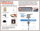
Step 4. Blue Tube to In-line GAC Filter
Step A: Insert the open end of the blue tube from the faucet into the fitting at
the end of the GAC In-line Filter. Use a 5/8” wrench to tighten the white
plastic nut securely.
Step 5. Green Tube Connection
Step A: Location the 1/4” Green tube plugged into the left (inlet) side of the unit.
Take the open end of the 1/4” Green tube and insert into the 1/4” quick
connect fitting on the plastic Adapt-A-Valve
TM
. Make sure to push the tube
in all the way to the tube stop.
Step 6. Reverse Osmosis Module Mounting
Step A: Determine best location for the RO module to be mounted to allow for
future system maintenance.
NOTICE
Make sure to allow a minimum of 1-1/2” under the system for
removing the bottom bowls.
There must be at least 1” of wood material for the mounting screw
to grip to or if mounting against a drywall and wood framed
When securing the screws to the mounting wall, make sure you provide one of the
following: (a) At least 1” of wood material for the screw to grip into; (b) drywall
clad wood framed wall where the mounting screws can be attached into the wood
studs; or (c)
Step B: Using the mounting holes on the bracket, mark the location for the
mounting screws on the cabinet wall under the sink.
Step C: In the parts bag, locate the two self tapping screws. Using an electric
drill with a Phillips bit, screw them into the cabinet at the marked
location. Hang the module on the screws using the mounting holes in the
bracket
NOTICE
The RO Module can be installed where it is standing in the cabinet
without being mounted to the wall.
TO
TIGHTEN
1/4”
GREEN TUBE
1-1/2”

Page 12
Step 7. Drain Saddle Installation
NOTICE
Drain Saddle fits standard 1 ¼” – 1 ½” drain pipes
NOTICE
If you have a garbage disposal, do not install the drain saddle downstream of it. Installation of
the drain saddle should be on a separate sink, if available.
The drain connection can instead be made at the dishwasher inlet port of the garbage disposal
using a Garbage Disposal Drain Line Adapter which is available for purchase from Watts Premier
(PN# 164020).
Step A: Gather the pieces of the drain saddle:
(1) Saddle - Front Portion
(1) Saddle - Rear Portion
(1) Foam Gasket
(2) Screws
(2) Nuts (for Screws)
NOTICE
The drain saddle must be installed at least 1 ½” above the nut of the
P-Trap elbow or cross bar from the garbage disposal to ensure proper
drainage.
Step B: The small square black foam gasket with a circle cut out of the middle
must be applied to the inside of the drain saddle. Remove sticky tape
backing and stick to the drain saddle as shown.
NOTICE
Take extreme caution to only drill through one side of the drain pipe.
Step C: The drain saddle must be installed at least 1 ½” above the nut of the
P-Trap elbow or cross bar from the garbage disposal to insure proper
drainage. Using the 3/8” drill bit, drill into the drain pipe at the best
available location as specified above.
Step D: Assemble the drain saddle around the drain pipe and align drain saddle
fitting opening with the hole drilled in the previous step - you may use
a small screwdriver to feed through the drain saddle into the drain pipe
to aid with the alignment. Using a Phillips screw driver tighten the drain
saddle bolts evenly and securely on both sides.
NOTICE
Do not over tighten the screws. It may crack the drain saddle.
NOTICE
The black 3/8” drain tube must be as SHORT and STRAIGHT as
possible to the drain saddle. Make sure there is a downward slope
from faucet to drain saddle to allow for proper drainage without
stretching or sagging of the tube. This is a gravity fed line and if
there is any bend or dip in the tube, the rinse water will not flow into
the drain properly. Water may back up and come out the air gap
hole in the back of the faucet.
Step E: Measure the 3/8” black tube from faucet to the drain saddle on the drain
pipe and make a straight cut to the correct length.
Step F: Connect the black tube to the open quick connect fitting on the drain saddle by pushing the tube all the
way to the tube stop.
1-1/2”
MINIMUM
P-TRAP
ELBOW
1-1/2”
MINIMUM
CROSS BAR
BLACK
3/8” TUBE
DRAIN

Page 13
Step 8. Red Tube Connection
Step A: Cut the excess red tube from RO faucet leaving a straight cut edge.
NOTICE
Do not overtighten
Step B: Using the white plastic union found in the parts bag, join the 1/4” red
tubing from the faucet to the 1/4” red tubing from the RO membrane
housing. Insert the red tube from RO faucet in one end of the white
plastic union and the red tube from RO membrane housing in the other
end. Use a 5/8” wrench to tighten both of the white plastic nuts securely
Step 9. Tank Ball Valve Installation
Step A: Teflon tape must be applied in a clockwise direction. Wrap (7 to 12
turns) around the male pipe threads (MPT) on the stainless steel fitting on
top of the tank.
NOTICE
Do not over-tighten.
Step B: Thread the elbow ball valve (supplied in the parts bag), by hand, onto the
stainless steel connector on the tank.
Step 10. Blue Tube Connection From Tank
Step A: Position tank in desired location. Stand it upright or lay it on its side (using the black plastic stand).
Measure the blue tube (marked “TANK”) from the RO module to the tank and cut it to length leaving a
straight, square edge. To connect the blue tube to the ball valve fitting, slip the blue tube through the
white compression nut, hand tighten the white nut and add 1/4 turn with a wrench.
Note: Set the blue ball valve knob in-line with the blue tube, this is the “open” position.
Step 11. Ice maker Connection
Step A: If you have a refrigerator / ice maker that you would like to connect to your RO system, you can connect
that to the blue tube (purified water) leading to the RO faucet.
NOTICE
A connection from the RO to the refrigerator / ice maker system must have an in-line valve
installed in-between so it can easily be closed to prevent water flowing to the ice maker during
start up and periodic maintenance. An Ice maker Connection Kit can be purchased through
Premier
7-12 TURNS
Operation

Page 14
Startup
NOTICE
If your RO system is connected to a refrigerator / ice maker, you must turn off the connection to
that appliance during the system startup.
Do not re-open the connection until after the system has been completely flushed (as described
below) and the tank is allowed to fill up completely in order for the appliance to work properly.
Discard the first batch of water or ice made from the RO water after startup.
Step A Turn on the water supply at both the cold water supply valve and Adapt-A-
Valve
TM
. Check the system for leaks and tighten any fittings as necessary.
(Continue to check frequently over the next 24 hours to ensure no leaks
are present).
Step B: Open the RO faucet and leave it open until water begins to trickle out (this
may take a few minutes and the water will come out slowly).
Step C: Close the RO faucet allowing the storage tank to fill with water. It may
take 3 to 6 hours to fill the tank completely depending on the production
capability of the membrane, local water temperature and water pressure.
NOTE: During the fill period you may hear water trickling which is a normal occurrence.
Step D: After the storage tank has filled, open the RO Faucet to flush the tank completely. You will know that the
tank is empty when the flow rate from the RO faucet is down to a trickle. Repeat this step two more
times. The fourth tank can be used for drinking.
NOTE: The flushing process should take about a day to complete.
NOTE: Flushing of the tank 3 times is only necessary during the initial startup and after replacing the
membrane.
NOTICE
Check frequently over the next 24 hours to ensure no leaks are present
OFF
ON
Maintenance

Page 15
Maintenance
WARNING
!
For proper performance and to help avoid exposure to contaminants, this system must be
installed, maintained and operated as specified in this Manual.
It is important to change out your filters at the recommended intervals as indicated in this system manual. When
replacing the filter elements, pay special attention to any cleaning instructions. Should you have any further questions
please refer to our web site at www.premierh2o.com or call our customer service department at 1-800-752-5582.
With proper installation and maintenance, this system will provide you with high quality water for years to come. All of
Premier’s water enhancement products are rigorously tested by independent laboratories for safety and reliability. If
you have any questions or concerns, please contact our customer service department at 1-800-752-5582 (outside USA
480-675-7995) or refer to our on-line troubleshooting guide at www.premierh2o.com.
NOTICE
If your RO system is connected to a refrigerator / ice maker, you must turn off the connection to
that appliance during the system maintenance.
NOTICE
The following is a minimum replacement schedule – More frequent filter replacement may be
required depending on your particular water conditions and use.
6 Month Maintenance
*Order filters by calling 1-800-752-5582 or buy online at www.premierh2o.com.
Replace: 5 micron Sediment Pre-Filter Part# 104017
5 micron Carbon Pre-Filter Part# 101009 (2 Needed for 5-Stage Unit)
NOTE: A filter housing wrench (part #164002) may be purchased from Premier to aid with filter removal
(not required)
Step A: Close the tank ball valve.
Step B: Turn off the incoming water supply to the RO by turning the knob at the
Adapt-A-Valve
TM
clockwise until it stops.
Step C: Open RO Faucet to depressurize system. Let system sit for 10 to 15
minutes after the tank is empty to let the system depressurize before
attempting to remove filter housings.
NOTICE
Water may be saved in a container for drinking or to rinse system
parts.
OFF
ON
STAGE 2
CARBON BLOCK
FILTER
STAGE 1
SEDIMENT
FILTER
FOUR-STAGE UNIT
STAGE 3
CARBON BLOCK
FILTER
STAGE 2
CARBON BLOCK
FILTER
STAGE 1
SEDIMENT
FILTER
FIVE-STAGE UNIT

Page 16
Step D: For more leverage you may leave the RO module attached to wall of
cabinet. If you are unable to access the module while it is mounted,
remove it prior to changing filters. Starting with the First Bowl on the
left (Stage 1), remove it by turning it clockwise (left), empty water, then
discard filter. Continue on to the 2nd Bowl (Stage 2) and then 3rd Bowl
(Stage 3 on the five-stage unit).
NOTE: If you have a four-stage system, it will only have two vertical housing
assemblies at the bottom
Step E: Clean the filter housings (bowls) with a mild soap solution and rinse with
water. Check O-rings and lubricate with water soluble lubricant. KY Jelly
®
,
canola oil or other water based lubricants may be used. Petroleum based
lubricants (such as Vaseline®) must not be used. If performing Annual
Maintenance, return to Step A below.
NOTICE
Before re-installing the filter bowls back on to the system, check
O-rings to make sure they are still in place.
Step F: Insert a new sediment filter (cloth like appearance) into the 1st filter
housing which is the one on the water inlet side (green tubing from the
Adapt-A-Valve
TM
) of the RO system, and re-install bowl.
Step G: Insert the new Carbon Block filter (White end caps & plastic netting) into
the second and third filter bowl and re-install bowl.
Step H: Turn on the water supply to the unit at the Adapt-A-Valve
TM
.
Step I: Keep the RO faucet open until water begins to trickle out (it will come out
slowly)
Step J: Close the RO Faucet and open the tank ball valve.
NOTICE
Do not over-tighten filter housing, overtightening may damage
O-ring(s), cause water leaks, or affect system performance.
Annual Maintenance
Replace: 5 micron Sediment Filter Part # 104017
5 micron Carbon Block Filter Part # 101009 (2 Needed for 5-Stage Unit)
GAC Final In-line Filter Part # 560005 (6” Filter) OR 560010 (10” Filter)
If you are sanitizing your unit, you will also need 1/4 cup (60mL) of common household bleach.
If not already complete, go back & perform Steps B through E in the 6 Month Maintenance.
NOTICE
During normal use, a reverse osmosis system tank may become fouled with organic
matter or in some cases bacteria from the water supply. This may result in an off-
taste or odor in your drinking water. The sanitizing of the unit is recommended to be
performed during your Annual Maintenance. The storage tank MUST be drained for this
process. If not sanitizing your unit, Skip to Step J
Step A: Remove the RO membrane from its housing and rest in a clean sanitary place. (Refer to “Membrane
Replacement” section on page 18 for directions on removing the membrane). Replace cap onto empty
membrane housing and re-connect green tubing.
Step B: Leaving the filters out, replace stage 2 & 3 empty filter housing (hand tight) onto unit. Measure & pour
1/4 cup of common household bleach into the 1st filter housing (Stage 1) and hand tighten onto unit.
Make sure
O-ring
is properly
seated
SANITATION STEPS
Filter Lid
O-Ring
Filter
Filter Bowl
To
Tighten
To
Loosen

Page 17
DANGER
!
IF BLEACH GETS IN EYES: Hold eye open and rinse slowly and gently with water for
15 - 20 minutes. Remove contact lenses if present, after the first 5 minutes, then
continue rinsing eye. Call a poison control center or doctor for treatment advice.
Step C: With the RO faucet in the closed position turn on the incoming water supply to the system by turning the
Adapt-A-Valve
TM
counter clockwise. Let the unit fill with water (approximately 8 minutes) allowing the
bleach to dilute.
Step D: Let the system sit idle for 1 minute
Step E: Drain the system completely
Step F: Let the system fill again (approximately 8 minutes) and sit idle for 10 minutes before draining the
system again.
Step G: Turn off the incoming water at the Adapt-A-Valve
TM
and open the faucet to make sure all the water has
been drained
Step H: Open the membrane housing and re-install the RO membrane while making sure not to kink the O-rings.
(Refer to “Membrane Replacement” section on page 18 for directions on installing the membrane).
Tighten the cap back on the housing and reconnect green tubing.
Step I: Remove filter housings Stage 1, 2 and 3 and empty water.
NOTICE
Before re-installing the filter bowls back on to the system, check O-rings to make sure they are
still in place and lubricate with water soluble lubricant.
Step J: Insert the new sediment filter (cloth like appearance) into the 1st filter housing which is the one on the
water inlet side (green tubing from the Adapt-A-Valve
TM
) of the RO system and re-install housing
Step K: Insert the new Carbon Block filter (White End Caps) into the 2nd and 3rd housing and re-install housing.
Step L: The final in-line filter is located on the blue tube between the storage tank and the RO faucet. Remove
it by loosening the compression fittings on both ends of the filter and replace with new filter. (Discard
used final filter after sanitizing)
NOTICE
The arrow on the final filter must be pointing towards the RO faucet / away from the RO storage
tank.
TIP: This is a good time to check the air pressure in your storage tank. For instructions please see
page 19.
Step M: Follow the Start Up Instructions on Page 14.
NOTICE
This reverse osmosis system contains a replaceable component (the RO membrane) which is
critical to the efficiency of the system. Replacement of this reverse osmosis membrane should
be with one of identical specifications as defined by Premier to assure the same efficiency and
contaminant reduction performance.
SANITATION STEPS (CONT)

Page 18
Membrane Replacement
Replace: RO Membrane Part# 560018
Membranes have a life expectancy between 2 and 5 years, depending on the incoming water conditions and the amount
the RO system is used. This reverse osmosis membrane is critical for effective reduction of total dissolved solids (TDS).
The product water should be tested periodically to verify that the system is performing satisfactorily.
Normally, a membrane would be replaced during a semiannual or annual filter change. However, if at any time you
notice a reduction in water production or an unpleasant taste in the reverse osmosis water, it could be time to replace
the membrane. Premier recommends replacing the membrane when TDS reduction falls below 75%.
NOTE: A water sample may be sent to Premier for a free diagnosis of your membrane performance. To
send a water sample, use two (2) clean containers and fill ½ cup of tap water in one container
and ½ cup of reverse osmosis water in 2nd container. Clearly label each sample. Send the
samples to the address listed on the cover of this manual attention “Water Samples”. Premier
will test the water and mail or call you with the results.
Step A: Turn off the incoming water supply to the RO system.
Step B: Open the RO Faucet and allow water to drain from the tank until it is
completely empty.
Removing the membrane:
Step C: Disconnect the hose from the cap of the membrane by loosening the
compression nut on the elbows
Step D: Remove the end cap from the membrane housing by turning it counter
clockwise to loosen.
Step E: Using a pair of pliers, grip the PVC tube of the RO membrane and pull
firmly on the membrane to remove from the housing and discard.
Installing the membrane:
Step F: Lubricate the O-rings on the new membrane with a water soluble lubricant
such as KY Jelly
®
. Insert the end with the two black O-rings on the PVC
tube first into the housing.
Step G: Once the membrane has been inserted into the housing, you must
take your thumb and give a firm push at the center plastic tube of the
membrane to properly seat it. Replace membrane housing cap and
tighten.
Step H: Re-attach the green tube to the elbow fitting on the end cap of the
membrane housing.
Step I: Follow the Start Up Instructions on Page 14.
To
Loosen

Page 19
Replacing the Faucet Battery
Step A: Remove the battery tray at the bottom of the faucet. Note: Water may
dribble out of the spout, use caution when handling the electronic
components.
Step B: Slide the old battery out and replace with new battery (“+” Positive Side
Up).
Step C: Replace battery tray. Once the battery is pushed into the clip, a red and
blue light will flash indicating proper installation.
KEEP AWAY FROM CHILDREN
This product contains a button (coin) cell battery. If swallowed, it could cause severe injury or
death in just 2 hours. Seek immediate medical help. Contact a Poison Control Center.
Check Air Pressure in the Tank
NOTICE
Check air pressure only when tank is empty of water!
Check air pressure in the storage tank when you notice a decrease in available water from
the RO system. Air can be added with a bicycle pump using the schrader valve that is
located on the lower side of the tank behind the blue plastic cap.
Step A: Turn off the incoming water supply to the RO.
Step B: Open the RO Faucet and allow water to drain from the tank until it is
completely empty.
TIP: When water from the RO faucet slows to a trickle, with the faucet
still in the open position, you may add air to the tank to purge any left over water, this will
ensure that the tank is completely empty.
Step C: Once all water in the tank is purged, check air pressure using an air pressure gauge, it should read
between 5 - 7 PSI. (Digital air pressure gauge is recommended)
Step D: Follow startup procedure on page 14.
Procedure for Extended Non-Use (More than 2 months)
Step A: Turn off the water supply to your RO system at the Adapt-A-Valve
TM
and open the RO faucet to drain the
storage tank. Once the storage tank is empty, remove all filter cartridges (order not important), place
them into a sealed plastic bag and store in your refrigerator.
NOTICE
Do Not Freeze!
To Restart your system
Step A: Reinstall the RO Membrane (per Page 18) and replace the filters (per Page 16 - Annual Maintenance).
Step B : Follow the Startup Procedure on Page 14.
NOTICE
If you have connected your RO system to a refrigerator / ice maker, make sure the ice maker is
off (do not allow water to flow to the ice maker) until the tank has been allowed to completely
fill.
POSITIVE (+) SIDE UP
TO REMOVE
SCHRADER
VALVE
Technical & Warranty Information
/