Page is loading ...

Assembly Instruction
Default access data (HTML + SFTP):
192.168.0.120
User: admin
Password: geheim
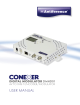
STC 4-16 CT CI

- 2 - STC 4-16 CT CI
Contents
1 Safety regulations and notes ........................................................................4
2 General information ....................................................................................6
2.1 Packing contents ............................................................................6
2.2 Meaning of the symbols used ..........................................................6
2.3 Technical data ...............................................................................6
2.4 Description ...................................................................................8
Block diagram ...............................................................................8
General ........................................................................................8
User ...........................................................................................10
Administrator access ...............................................................10
Guest access ..........................................................................10
3 Assembly ..................................................................................................11
3.1 Installing the device .....................................................................11
3.2 Device overview ..........................................................................12
3.3 Potential equalisation (PE) .............................................................13
3.4 Connecting the device ..................................................................13
3.5 CI Slots .........................................................................................14
4 Configuration / Updates ............................................................................15
4.1 Initial configuration ......................................................................15
4.2 Configuration ..............................................................................18
Overview window .......................................................................18
Perform changes .........................................................................19
Number format............................................................................20
Configuration menus ....................................................................20
Input .....................................................................................20
Output ..................................................................................22
Filter & CA ............................................................................26
NIT .......................................................................................31
LCN – Logical Channel Numbering ..........................................35
System menus .............................................................................37
Logbook ................................................................................37
Notification ...........................................................................38

- 3 - STC 4-16 CT CI
Network ................................................................................40
OpenVPN .............................................................................41
Security .................................................................................42
- Administrator access .............................................................42
- Guest access ........................................................................42
Firmware ...............................................................................43
- Output Modulation of Head-end Station: ..................................43
- System settings: ....................................................................44
- Firmware update: .................................................................44
- Backup: ...............................................................................45
- Manager: ............................................................................45
- Reset to factory defaults: ........................................................45
- System restart: ......................................................................46
- Ping (Network Diagnostic Tool): ..............................................46
User ......................................................................................46
5 Multiple satellite reception .......................................................... 47
5.1 Reception of up to 4 satellites ........................................................47
Overview ...................................................................................47
Menu Configuration > Input ..........................................................48
Installing the SDUC 516 ...............................................................49
Potential equalisation (PE) .........................................................49
Connecting the SDUC 516 ..........................................................50
6 Media Player ..............................................................................51
6.1 Media2TS – Converting Software ..................................................51
6.2 Transfer the video file to the head-end station ..................................52
6.3 Start the Media Player ..................................................................53
6.4 Add the Media Player Stream into the NIT ......................................53
6.5 Add the Media Player Stream into the LCN list ................................54
7 Channel and frequency tables ....................................................................55

- 4 - STC 4-16 CT CI
1 safety regulations and notes
• The devices meet the EU directives 2011/65/EU, 2014/30/EU and
2014/35/EU.
• This device is subject to the provisions of protection class I. Operate the
device only to mains sockets with protective conductor connection!
• If the power cord needs to be replaced, only use an OEM power cord.
• The standards EN/DIN EN 50083 resp. IEC/EN/DIN EN 60728 must be
observed, especially concerning equipotential bonding and earthing.
• Observe the relevant country-specific standards, regulations and guidelines
on the installation and operation of antenna systems.
• Before starting installation or service work disconnect the receiving system
from mains.
• Do not perform installation and service work during thunderstorms.
• Assembly, installation and servicing must be carried out by an authorised
electrician.
• For a complete disconnection from the mains, the mains plug must be pulled
out of the mains socket. Ensure that the mains plug can be pulled out without
difficulties.
• The head-end station should only be installed in a room where the permis-
sible ambient temperature range (0 °C … +50 °C ) can be maintained, even
during fluctuations in climatic conditions.
• Make sure there is a minimum space of 10 cm on either side and 50 cm
above and below.
• To avoid too strong interacted heating of the head-end stations it is not
admissible to mount them one upon the other without using thermic precau-
tions (e.g. permanently air recirculation, ventilation, heat deflectors etc.).
• If additional fans are to be used to circulate the air, ensure that the system
will be shut down (disconnected from mains) should any one of the fans fail.
• Install the head-end station
- in a dry, dust-free environment, in such a manner that it is protected from
moisture, fumes, splashing water and dampness
- where it is protected from direct exposure to sunlight
- on a vibration-free wall or floor construction
- not within the immediate vicinity of heat sources
• In case of the formation of condensation wait until the system is completely
dried.
• Ensure that the head-end station is adequately ventilated.
• Do not cover the ventilation openings!
• Do not install the head end in cabinets or recesses which are not ventilated.

- 5 - STC 4-16 CT CI
• Do not place any vessels containing liquids on the head-end station.
• Do not place anything on the head-end station which could initiate fires
(e.g. candles).
• Due to the risk of fires caused by lightning strikes, we recommend that
all mechanical parts (e.g. distributor, equipotential bonding rail, etc.) be
mounted on a non-combustible base. Wood panelling, wooden beams,
plastic covered panels and plastic panels are all examples of combustible
bases.
• Avoid short circuits!
• To ensure electromagnetic compatibility, make sure all connections are tight
and that the covers are screwed on securely.
• No liability is accepted for damage caused by faulty connections or inap-
propriate handling of the device.
• The firmware contains components which are licensed as Open Source
software. The components to which this relates and the respective license
terms can be called up via menu Help/Licences.
This parts of software source code can be provided at cost price on CD
upon request. The licensee is granted a non-exclusive right of use for the
Open Source Software by the respective right holders used; the conditions
stipulated by the respective valid license terms apply. The license terms of
this license only apply to the components which are not listed as Open
Source software.
In relation to the licensor the regulations on liability and warranty in these
license terms apply for the whole software. The liability and warranty regu-
lations of the Open Source licenses only apply in relation to the respective
right holders.
• Test the firmware versions of the device and update them if necessary. The
current firmware version can be found at "www.mygss.eu".
Take action to prevent static discharge when working on the device!
Electronic devices should never be disposed of in the household rubbish. In accordance
with directive 2002/96/EC of the European Parliament and the European Council from
January 27, 2003 which addresses old electronic and electrical devices, such devices
must be disposed of at a designated collection facility. At the end of its service life,
please take your device to one of these public collection facilities for proper disposal.

- 6 - STC 4-16 CT CI
2 general information
2.1 PaCki n g Co nt en ts
1 STC 4-16 CT CI 1 LAN cable
1 Brief assembly instructions 1 Mains cable
2.2 mea n in g o f th e sym bo l s us ed
Important note
Danger by electrical shock
—> General note
• Performing works
2.3 teC h niC al data
The devices meet the following EU directives:
2011/65/EU, 2014/30/EU, 2014/35/EU
The product fulfils the guidelines and standards for CE labelling (page 56).
Unless otherwise noted all values are specified as "typical".
RF input DVB-S/S2 (ETSI 300 421)
Frequency range: ....................................................... 950 … 2150 MHz
DVB-S modes: ............................................................................... QPSK
DVB-S2 modes: ........................................ QPSK, 8PSK, 16APSK, 32APSK
Symbol rate DVB-S: ............................................ QPSK: 1 … 45 MSymb/s
Symbol rate DVB-S2:
QPSK ................................................................... 4.5 … 45 MSymb/s
8PSK .................................................................... 4.5 … 45 MSymb/s
16APSK ................................................................ 4.5 … 39 MSymb/s
32APSK ................................................................ 4.5 … 32 MSymb/s
Maximum data rate/tuner ......................................................... 83 MBit/s
Level range: ............................................................ 60 dBμV … 80 dBμV
Input impedance: ............................................................................75 Ω
LNC supply total: ................................................................max. 500 mA

- 7 - STC 4-16 CT CI
RF output QAM
Frequency range: ............................................. 42.0 MHz … 868.0 MHz
Channels: ............................................................................ S21 … C69
Types of modulation: ......................................QAM 16, 32, 64, 128, 256
Dynamic phase error: .................................................................... < 0.2°
MER: ............................................................................................45 dB
Symbol rate ................................................................. 1000…7500 kBd
Output level: ......................................................................80…96 dBμV
Output impedance: ......................................................................... 75 Ω
RF output COFDM
Frequency range: ............................................. 42.0 MHz … 868.0 MHz
Channels: ..........................................................C5 … C12, C21 … C69
Types of modulation: ........................................ QPSK, 16 QAM, 64 QAM
Transmission modes ............................................................................ 2k
Code rates ....................................................... 1/2, 2/3, 3/4, 5/6, 7/8
Guard intervals .................................................... 1/4, 1/8, 1/16, 1/32
Output level: ......................................................................80…96 dBμV
Output impedance: ......................................................................... 75 Ω
LAN interface for HTML control/update
Standard: .............................................................................100-BASE-T
Connections
SAT inputs: ............................................................................. 4 F sockets
RF output: .............................................................................. 1 F socket
RF test output (-25 dB): ............................................................ 1 F socket
LAN: ................................................................................ 1 RJ 45 socket
Common Interfaces ...............................................................................6
General
Mains voltage: .................................................. 200…240V~, 50/60 Hz
Power consumption without LNC/CI .................................................40 W
Maximum Power consumption: ........................................................ 80 W
Admissible ambient temperature: ............................................0 … +50 °C
Dimensions (WxHxD): ............................................. 341 x 282 x 105 mm
Weight: .......................................................................................... 7 kg

- 8 - STC 4-16 CT CI
2.4 de sC ri P t io n
The head-end station converts 16 transponders modulated acc. to DVB-S/
DVB-S2 standard (up to 32 APSK) into 16 DVB-C or DVB-T modulated trans-
ponders. In conjunction with multiswitches SDUC516 up to four satellites can
be received (multiple satellite reception – option dCSS/Unicable II page 47).
blo Ck d i agr am
Tuner "1"
RF OUT
TPS
STC 4-16 CT CI
Modulator
"1"
Tuner "6"
TPS
Modulator
"6"
Tuner "7"
TPS
Modulator
"7"
Tuner "16"
TPS
Modulator
"16"
Combiner
TEST
6
x
CI
–25dB
SAT IN 1
4 x SDUC 516
ASTRA 19,2
ASTRA 23,5
Hotbird
Türksat
Option dCSS/Unicable II
SAT IN 4
SAT IN 2
SAT IN 3
f1
f2
f3
f4
f1
f2
f3
f4
f1
f2
f3
f4
f1
f2
f3
f4
ge ner al
The station is equipped with four SAT IF inputs, one RF output and one test
output (–25 dB). It is preset to receive the most popular ASTRA transponders.
Different programming is possible at any time.
Each of the 16 tuners can be assigned to any SAT input.
Using an adequate CA modules scrambled channels can be descrambled via
tuners "1"…"6".
The kind of modulation at the output can be selected between QAM or COFDM
(menu System > Firmware).
—> Note for COFDM outputs:
Since satellite transponder can transmit higher data rates than DVB-T
transponder, you need to remove Services menu from the data stream
in menu "Filter & CA"!
Select SD transponder in menu input.
Just two HD services with high data rates may lead to an output data
overflow in COFDM.

- 9 - STC 4-16 CT CI
The output channels and levels of the channel strips can be set freely.
The configuration of the station is to be done via an HTML user interface via a
PC and a standard HTML browser connected to the LAN input.
GSS
OpenVPN
Server
After the initial setup, you have
worldwide access to the station via
an OpenVPN connection – by PC,
tablet or smart phone with Internet
access.
—> When using mobile terminals – dependent on your mobile contract – ad-
ditional connection costs / data transfer costs may also be incurred here.
16 LEDs provide an indication of the SAT IF input signal quality based on their
colour and indicate if the respective channel strip is switched on (LED illumi-
nates) or off. If there is an overflow of the output data rate, the corresponding
LED blinks.
An integrated MediaPlayer enables the output of a video stream (max. data
rate 10MBit/s) in a loop instead of transponder 16. For this you need a trans-
port stream format file (*.ts) that you can produce with the program Media2TS
from all popular video formats. The software Media2TS can be downloaded
from "www.mygss.eu".
The maximum file size is 4 GB.
The file can be copied via any "SFTP file transfer" software (e.g. WinSCP)
into the station. The SFTP access data correspond with the access data for the
HTML user interface.

- 10 - STC 4-16 CT CI
us e r
adm i n is tr ato r aCC ess
The user admin has access to all menus and may make changes.
—> The default password for the user admin is geheim.
gu est aCC ess
The user gast has access to (almost) all menus, but may not make any changes.
—> The default password for the user gast is gast.
A guest access is shown in all menus:
The button has no function!

- 11 - STC 4-16 CT CI
3 assembly
3.1 in stal li n g th e de v iCe
– The device must not be operated lying down, since the function of the heat
sink will be severely restricted. Only with vertically arranged cooling fins
sufficient cooling is ensured.
– The device should only be installed in a room where the permissible ambi-
ent temperature range (0 °C … +50 °C ) can be maintained, even during
fluctuations in climatic conditions.
– Mount the device on a non-combustible base.
– Use mounting material suitable for the wall properties.
– Position the device with a minimum distance on the left and right side of
10 cm, below and above 50 cm.
• Attach four mounting screws at the installation site. The drilling distances
are shown in the drawing below.
STC 4-16 CT CI
318 mm
222 mm
# #
Ø6 mm
Ø12 mm
• Hang the unit with the mounting supports
13
on the 4 screws.
• Tighten the screws.

- 12 - STC 4-16 CT CI
3.2 dev i Ce ov e rvi e w
1
2
3
4
5
6
7
8
13
14
15
16
9
10
11
12
1 2 3 4 5 6 7 78
913 1310 11 12
STC 4-16 CT CI
CI 1
CI 6
CI 2
CI 5
CI 3
CI 4
9 10 11 12
78
14
765431
1
Connector potential equalisation
2
Reception LEDs of tuners 1…16
3
SAT IF input vertical low*
4
SAT IF input vertical high*
5
SAT IF input horizontal low*
6
SAT IF input horizontal high*
* Factory defaults for ASTRA reception, can be changed individually.
7
RF output;
Test output –25dB
8
Not used
9
IEC connector C14; connector for mains cable
10
Reset IP address and password
(hold depressed for more than 5 seconds)
to
192.168.0.120 / geheim
11
Not used
12
Configuration interface**
13
Mounting support
14
CI slots
** Use at least CAT6 LAN cables!

- 13 - STC 4-16 CT CI
3.3 Pote n ti al eq ualisat i on (Pe)
Equalise the potential (PE) in accordance with IEC/EN/DIN EN 60728.
•
Connect the PE connection terminal
1
to a PE rail (supplied by customer)
using the PE wire (Cu 4 mm
2
- 9 mm
2
).
3.4 Con n eC tin g th e d evi C e
• Connect the SAT IF inputs…
3
vertical low*
4
vertical high*
5
horizontal low*
6
horizontal high*
… to the corresponding outputs of an LNB.
*Factory defaults for the preprogrammed ASTRA reception, can be changed individually.
• Make sure that all inputs have the same level!
• Connect the attached mains cable to the IEC connector C14
9
.
—> If you would like to integrate the device to an existing plant, now
first you should connect it to the mains and perform all settings (Con-
figuration page 15).
• Connect the mains cable to a mains socket with protective conductor con-
nection. Thereby note the voltage specified on the device.
—> This device has no power switch and starts immediately after con-
necting the operating voltage.
• Configure the device (page 15).
• If the programming is finished connect the RF output
7
to the cable net-
work.
—> For multiple satellite reception observe the dCSS/Unicable II mode
from page 47 on.

- 14 - STC 4-16 CT CI
3.5 Ci slots
The CI slots are located under the CI cover on top of the case.
• Unscrew 4 screws
15
and remove the cover.
15
—> Note for the selection of slots:
Slots 1…6 are assigned to the tuners 1…6. If a CA module is not
sufficient to descramble all channels of a transponder, alternatively
the modules 6…4 can be assigned to the tuners 1…3 additional:
– Module 1 + 6 for tuner 1,
– Module 2 + 5 for Tuner 2 and
– Module 3 + 4 for Tuner 3.
• Insert the CA modules …
– for slots 1 … 3 with the (thicker) top side towards housing-front, …
– for slots 4 … 6 with the (thicker) top side towards rear panel (heat sink).
1
6
2
5
3
4
• Final mount again the CI cover (EMC).

- 15 - STC 4-16 CT CI
4 Configuration / uPdates
The configuration of the station is to be done via an HTML user interface via a
PC and a standard HTML browser.
4.1 in itial Co n fi g ur at io n
•
Connect a PC via a CAT6 LAN cable directly to the Configuration interface
12
.
—> The PC and the head-end station must be within the same network
(same IP address range). Cookies must be accepted and JavaScript
must be active.
Use current browser versions.
—> Example for IP address setting with Windows 7 operating system:
• For the initial setup open the properties for TCP/IPv4 of the PC:
> Control Panel
> Network and Sharing Center
> LAN connection
> Properties

- 16 - STC 4-16 CT CI
> Internet Protocol Version 4 (TCP/IPv4)
> Properties
• Activate point "Use the following IP address".
• Enter e.g. 192.168.0.2 for the IP address.
• Enter for the Subnet mask 255.255.255.0.
• Confirm the setting with "OK".

- 17 - STC 4-16 CT CI
• Start the browser, enter the IP address of the device (factory default is
192.168.0.120) and start the establishment of the connection.
• Enter user "admin" and your Password and click on button "Login".
The default password is "geheim".
—> We recommend that you replace the default password to a pass-
word of your choice in order to prevent unauthorized access to the
head-end station (menu System > Security)!
—> For further logins observe the menus System > Network and System
> OpenVPN!
—> The Overview window is displayed.
First, an "empty" table is displayed (as with all menus). While the
data is read from the device ...
… is displayed.
—> Changes in the menus are only transmitted to the head-end station
when you click the button!

- 18 - STC 4-16 CT CI
4.2 Con f ig u r ati on
ov erv i ew w i n dow
50
51
57
56
54
55
58
53 60
52
59
65
50
Via the selection System you have access to the menus of the System
settings: Logbook (page 37); Notification (page 38); Network (page 40);
OpenVPN (page 41); Security (page 42); Firmware (page 43); User (page 46)
51
In all menus you will return to the Overview via the button Overview.
52
Via the selection Configuration you have access to the menus of the Con-
figuration settings: Input (page 20); Output (page 22); Filter & CA (page 26);
NIT (page 31); LCN (page 35)
53
Herein the installed firmware version is displayed.
54
This location text can be modified arbitrary in menu System/User (page 46).
—> If you remote control head-end station at different locations, herein
you can enter the location and a local contact person.
55
Select menu language (English/German)
56
Herein the current system temperature as well as date and time of the last
login is displayed.
—> If a system temperature of 85°C will be reached, the system will be
shut down.

- 19 - STC 4-16 CT CI
57
Via button Logout you can leave the graphical user interface.
58
Via the Help menu you can call up the assembling instructions (PDF) as
well as a ZIP file containing a list and all licences of the used Open-
Source software.
59
Overview of the transponder set, with input frequency, C/N value,
output frequency and data rate. Via the background colour of col-
umn Line you are informed about the quality of the input signals
( good/ bad/ no signal), a possible exceeding the output data
rate ( ), or whether the modulator is switched off ( ). An activated Me-
dia Player at line 16 is also indicated ( ).
—> If in menu Configuration/Input (page 20) transponder names are
NOT assigned, the name of the first station of each transponder is
displayed.
—> The maximum displayed C/N value is 15.0dB at DVB-S resp.
20.0dB at DVB-S2. This means the actual value is ≥15/20dB.
60
Output indication QAM or COFDM
—> Setting in menu System > Firmware (page 43).
65
Via button Download a configuration protocol can be stored as text file
resp. opened using a text editor.
—> From this protocol file e.g. a list of the programmed stations can be
prepared using e.g. a text editor.
Per fo r m Cha ng es
Before leaving a menu, changes must be transmitted to the head-end station.
• Therefore click on button .
After that is displayed for a short time in the upper right corner.

- 20 - STC 4-16 CT CI
numb e r fo r m at
For entering/indication of the different IDs the number format can be set to
hexadecimal or decimal in menu System > Firmware.
Co n fi g ur at i on m e n us
in Pu t
100
101
102
110
111
103
104
105 106 107 108 109
112
101
102
103
—> Via the background colour of column Line you are informed about
the quality of the input signals ( good/ bad/ no signal), a
possible exceeding the output data rate ( ), or whether the modu-
lator is switched off ( ). An activated Media Player at line 16 is
also indicated ( ).
100
In column f
LNB
, enter the LNB Oscillator frequencies for the 4 inputs – de-
pendent on the LNB used.
—> In dCSS/Unicable II operating this column is omitted. You need
Quattro LNBs with 9.75 / 10.6 GHz oscillator frequency. For mul-
tiple satellite reception observe the dCSS/Unicable II mode from
page 47 on.
/