Page is loading ...

Warranty Information
for your TrueCut Cutting Table
The Cutting Table has a One-Year limited warranty on all parts. The Grace Company will repair
or replace, at its discretion, any part with problems due to manufacturing, or defects in materials.
This warranty does not cover parts damaged through misuse, improper storage, improper assembly,
loss, natural events, and willful destruction. Parts must be returned to the Grace Company, shipping
prepaid, before we can repair or replace them. We will promptly return the repaired/replaced part at
our expense if done within a year of the purchase date.
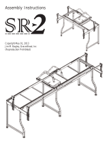
Copyright 2012
Jim M. Bagley, GraceWood, Inc
(Reproduction Prohibited)
Print Date 01-15-12
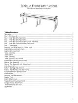
Table of Contents
Parts List
Parts list.............................................
Hardware...........................................
Assembly Steps
Step 1: Caster Wheels.........................
Step 2: Height Adjustable Legs............
Step 3: Shelves...................................
Step 4: Main Table..............................
2
2
3
3
3
4
Cutting Table

Hardware
M6 X 60mm Socket Button
Head Cap Screw (SBHCS)
(8)
M6 X 55mm Socket Button
Head Cap Screw (SBHCS)
(4)
M6 X 10mm
Connector
Bolt (12)
Parts List
Table Side (2)
Main Table (1)
Shelf (2)
Short Support (4)
Long Support (2)
Caster Wheel (8)
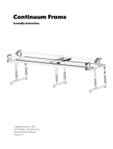
Welcome!
As you begin assembly of your new Cutting Table, keep in mind the following:
1: The assembly process will be simple and step by step.
2: Read through each step completely before beginning that step.
3: Using the parts list as a reference, take the parts out of the box and make
sure that you have all the parts.
4: Identify hardware packets: All hardware is separated by type and each
packetislabeledforeaseinidentication.
12mm Open End
Wrench
4mm Allen
Wrench

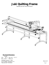
Step 1: Caster Wheels
Parts Needed:
8- Caster Wheels
2- Table Side
1-1: Turn each Table Side on its top when inserting
Caster Wheels.
1-1: Insert a Caster Wheel into each leg, as shown
on Fig. 1-1.
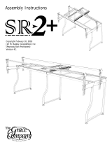
Step 2: Height Adjustable Legs
To adjust the height of your table, un-thread the M6 X
32mm SBHCS and pull the leg down to the desired height.
Align the hole in the height adjustable leg with the desired
hole on the table leg and insert the M6 X 32mm SBHCS
back into the M6 Flat Washer and M6 Nylock Nut, as shown
in Fig. 2-1.
Table Height
1st hole 32”
2nd hole 33”
3rd hole 34”
4th hole 35’’
5th hole 36”
6th hole 37”
bottom hole 38”
Note: Open the Table Extension Legs on the Table
Sides to help stand up the table during assembly.
Note: Before installing each Caster Wheel, make sure
the locking switch on the wheel is engaged, so the
wheels can’t roll around.
Height Adjustable
Leg
M6 Nylock
Nut
M6 X 32mm
SBHCS
Fig. 2-1
Fig. 1-1
Caster Wheel
Locking Switch
Step 3: Shelves
Parts Needed:
4- M6 X 60mm SBHCS
4- M6 X 55mm SBHCS
2- Short Support
2- Long Support
2- Table Side
2- Shelf
M6 X 60mm SBHCS
Table Side
Short Support
Shelf
Table Extension
Leg
Fig. 3-1
Note: Do not tighten SBHCS screws until noted in step 4, to
help prevent the table from getting out of square.
3-1: Insert (2) M6 X 60mm SBHCS into the bottom holes on
each Table Side and thread the screws into (2) Short Supports, as shown in Fig. 3-1.
3-2: Remove the cover on the pre-installed double sided sticky tape. Line up a Shelf with the edges
ofthetableframeandpressrmly.
Table Side
M6 Flat
Washer

3-3: Insert (2) M6 X 55mm SBHCS
into the middle holes on each Table
Side and thread the screws into (2)
Long Supports, as shown in Fig.
3-2.
3-4: Repeat Step 3-2 for the Middle
Shelf.
3-5: Insert (2) M6 X 60mm SBHCS
into the top holes on each Table
Side and thread the screws into (2)
Short Supports, as shown in Fig.
3-3.
Congratulations you have completed assembly of your new TrueCut Cutting Table!
For any further questions, or if anything appears to be missing/damaged please contact your
dealer or the Grace Company directly at 1-800-264-0644 or info@graceframe.com.
4-1: Insert (12) M6 X 10mm Connector Bolt
through each of the inside holes on table
hinges and into the Main Table as shown in
Fig. 4-1.
4-2: Completely tighten all the screws at
this time. Make sure you start at one end
of the table and work your way to the other
end, keeping your supports lined up as you
go.
Step 4: Main Table
Parts Needed:
1- Main Table
12- M6 X 10mm Connector Bolt
M6 X 10mm Connector Bolt
Fig. 4-1
Main Table
M6 X 55mm SBHCS
Long Support
Shelf
Fig. 3-2
Short Supports
M6 X 60mm
SBHCS
Fig. 3-3
/