
User Manual
GL2000/GL2010
– Data Logger
Version
2.4
English

Imprint
Vector Informatik GmbH
Ingersheimer Straße 24
D
-70499 Stuttgart
Vector reserves the right to modify any information and/or data in this user documentation without notice.
This documentation nor any of
its parts may be reproduced in any form or by any means without the prior written consent of Vector. To the
maximum extent permitted
under law, all technical data, texts, graphics, images and their design are protected by copyright law, various international
treaties and
other applicable law. Any unauthorized use may violate copyright and other applicable laws o
r regulations.
© Copyright 201
7, Vector Informatik GmbH. Printed in Germany.
All rights reserved.

User Manual GL2000/GL2010 – Data Logger Table of Contents
© Vector Informatik GmbH Version 2.4 - I -
Table of Contents
1 Introduction 3
1.1 About this User Manual 4
1.1.1 Certification 5
1.1.2 Warranty 5
1.1.3 Support 5
1.1.4 Trademarks 5
2 GL2000 – Data Logger 7
2.1 General Information 8
2.2 Features 9
2.2.1 Connectors 9
2.2.2 SD/SDHC Memory Card 12
2.2.3 Serial Number 14
2.2.4 LED Display 15
2.2.5 Digital Input/Output 16
2.2.6 Analog Inputs 17
2.2.7 Serial Interface 17
2.2.8 Real Time Clock with Battery 17
2.2.9 Beep 19
2.2.10 Wake-up / Sleep 19
2.2.11 CCP/XCP 20
2.2.12 Diagnostics 21
2.3 Operating Modes 21
2.4 CAN and LIN 22
2.4.1 CAN 22
2.4.2 CAN Piggybacks 22
2.4.3 LIN 24
2.5 GPS Mouse 25
2.6 Ethernet 25
2.7 3G (UMTS) 26
2.8 Technical Data 27
2.9 Included with Delivery 28
2.10 Accessories 28
3 Installation Configuration Programs 29
3.1 Overview 30
3.2 Installation Vector Logger Configurator 30
3.2.1 Requirements 30
3.2.2 Setup 31
3.2.3 Overview 31
3.2.4 Quick Start 32
3.3 Installation G.i.N. Configuration Program 33
3.3.1 Requirements 33
3.3.2 Setup 33
3.3.3 Overview 33
3.3.4 Quick Start 34
4 Index 37

User Manual GL2000/GL2010 – Data Logger Table of Contents
© Vector Informatik GmbH Version 2.4 - II -


User Manual GL2000/GL2010 – Data Logger Introduction
© Vector Informatik GmbH Version 2.4 - 4 -
1.1 About this User Manual
To find information
quickly
The user manual provides you the following access helps:
> At the beginning of each chapter you will find a summary of the contents,
> In the header you can see the current chapter and section,
> In the footer you can see to which version the user manual replies,
> At the end of the user manual you will find an index.
Conventions
In the two following charts you will find the conventions used in the user manual
regarding utilized spellings and symbols.
Style Utilization
bold
Blocks, surface elements, window- and dialog names of the
software. Accentuation of warnings and advices.
[OK] Push buttons in brackets
File | Save Notation for menus and menu entries
Windows Legally protected proper names and side notes.
Source code
File name and source code.
Hyperlink Hyperlinks and references.
<STRG>+<S> Notation for shortcuts.
Symbol Utilization
Here you can find additional information and hints that eases the
work with the loggers.
This symbol calls your attention to warnings.
Here you can find additional information.
Here is an example that has been prepared for you.
Step-by-step instructions provide assistance at these points.
Instructions on editing files are found at these points.
This symbol warns you not to edit the specified file.

User Manual GL2000/GL2010 – Data Logger Introduction
© Vector Informatik GmbH Version 2.4 - 5 -
1.1.1 Certification
Certified Quality
Management System
Vector Informatik GmbH has ISO 9001:2008 certification.
The ISO standard is a globally recognized standard.
1.1.2 Warranty
Restriction of
warranty
We reserve the right to modify the contents of the documentation or the software
without notice. Vector disclaims all liabilities for the completeness or correctness of
the contents and for damages which may result from the use of this documentation.
1.1.3 Support
You need support? You can get through to our hotline at the phone number
+49 711 80670-200
or you write an email to support@vector.com.
1.1.4 Trademarks
Protected
trademarks
All brand names in this documentation are either registered or non registered
trademarks of their respective owners.


User Manual GL2000/GL2010 – Data Logger GL2000 – Data Logger
© Vector Informatik GmbH Version 2.4 - 7 -
2 GL2000 – Data Logger
In this chapter you find the following information:
2.1 General Information page 8
2.2 Features page 9
Connectors
SD/SDHC Memory Card
Serial Number
LED Display
Digital Input/Output
Analog Inputs
Serial Interface
Real Time Clock with Battery
Beep
Wake-up / Sleep
CCP/XCP
Diagnostics
2.3 Operating Modes page 21
2.4 CAN and LIN page 22
CAN
CAN Piggybacks
LIN
2.5 GPS Mouse page 25
2.6 Ethernet page 25
2.7 3G (UMTS) page 26
2.8 Technical Data page 27
2.9 Included with Delivery page 28
2.10 Accessories page 28

User Manual GL2000/GL2010 – Data Logger GL2000 – Data Logger
© Vector Informatik GmbH Version 2.4 - 8 -
2.1 General Information
GL2000 The GL2000 is a data logger with USB interface which processes CAN messages
with either 11-bit or 29-bit identifiers and LIN messages. Furthermore, received
messages and analog values can be logged on an inserted SD/SDHC card. The
configuration of the logger is done with the Vector Logger Configurator or the G.i.N.
configuration program. The installation is described in chapter 3.
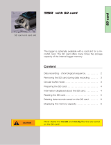
GL2010
The GL2010 is equivalent to the GL2000 and differs only in the design of the housing
and the connections (watertight according to IP65). The SD card is located in the
housing and is no longer accessible from the outside. The opening for the speaker is
eliminated.
Note: Please note that the housing of the GL2010 must not be opened under any
circumstances, since otherwise the IP65 protection class of the data logger is no
longer guaranteed. The SD/SDHC card, the piggybacks, and the battery may only be
replaced by Vector Informatik GmbH. For more information, please contact the Vector
Support.
Figure 1 – GL2000 (left), GL2010 (right)
Info: Due to the openings in the housing for the LED, leak tightness may not be
guaranteed if the label is damaged.

User Manual GL2000/GL2010 – Data Logger GL2000 – Data Logger
© Vector Informatik GmbH Version 2.4 - 9 -
2.2 Features
2.2.1 Connectors
General information The loggers have the following connectors:
> USB connector: data transfer between PC and logger
> DSUB25 connector Vehicle containing:
4 CAN channels
2 LIN channels
2 digital inputs/outputs
4 analog inputs
Battery and ground
Ignition
> DSUB15 connector Extension containing:
2 digital inputs/outputs
GPS module
Switch box
External supply for galvanically isolated piggybacks
> SD/SDHC card slot (externally accessible)
> AUX connection for logger accessories
> Event connector for switch box E2T2L (GL2000 V2.0 only)
DSUB25
pin assignment
The pins of the Vehicle connector have the following meaning. The colors refer to the
included connection cable Vehicle.
Pin Assignment Color Pin Assignment Color
1 Battery (VCC) white 14 CAN3 Low white/blue
2 RS232 Rx white/green 15 CAN1 High yellow
3 RS232 Tx brown/pink 16 CAN1 Low green
4 GND brown 17 CAN4 High white/gray
5 Battery (VCC) white/black 18 CAN4 Low white/pink
6 I/O 1 white/yellow 19 CAN2 High grey
7 GND brown/red 20 Wake/KL15 black
8 I/O 2 brown/yellow 21 CAN2 Low pink
9 Analog In 1 grey/pink 22 GND brown/blue
10 Analog In 2 red/blue 23 LIN 1 lilac
11 Analog In 3 blue 24 LIN 2 red
12 Analog In 4 brown/green 25 K-Line brown /gray
13 CAN3 High white/red
The three GND pins are connected together internally and have the same potential as
the power supply ground.

User Manual GL2000/GL2010 – Data Logger GL2000 – Data Logger
© Vector Informatik GmbH Version 2.4 - 10 -
Caution: It is recommended to connect the logger to the same voltage supply (e.g.
battery of the vehicle) as the vehicle or test equipment, respectively.
If two different voltage supplies are used for the logger and the test equipment, the
ground (GND) pins of the two voltage supplies must be connected.
Connection cable
Vehicle
In the delivery a connection cable for the Vehicle connector is included with the
following connections.
CAN1
DSUB9 with black cap
CAN2
DSUB9 with red cap
LIN1
DSUB9 with yellow cap
V
batt
/KL30
red pin plug
GND
black pin plug
Wake/KL15
red pin plug
All other wires have open wire ends. If these wires are not used, it is recommended to
terminate them. This prevents short circuits between the open wires. At the same
time the EMC properties are improved.
Note: The connecting cable does not conform to IP65.
DSUB15
pin assignment
The pins of the Extension connector have the following meaning.
Pin Assignment Pin Assignment
1 CAN3_Vbatt 9 CAN3_GND
2 CAN4_Vbatt 10 CAN4_GND
3 LIN1_Vbatt (24V) 11 I/O 4
4 LIN2_Vbatt (24V) 12 V+ (switch box)
5 I/O 3 13 T1 (switch box)
6 V+ (GPS) 14 T2 (switch box)
7 Rx (GPS) 15 GND
8 Tx (GPS)
The four GND pins on the connectors Vehicle and Extension are connected together
internally and have the same potential as the power supply ground.
Connection cable
Extension
(not for GL2000
V2.0)
In the delivery a connection cable for the Extension connector is included.
The delivered switch box E2T2L is connected to the 5-pin Binder connector. The PS2
connector is provided for an optional serial GPS mouse. The contacts for further pins
are loosely added.
You can find further information about the GPS mouse in chapter 2.5.

User Manual GL2000/GL2010 – Data Logger GL2000 – Data Logger
© Vector Informatik GmbH Version 2.4 - 11 -
Note: The connecting cable does not conform to IP65.
Event connection
(GL2000 V2.0 only)
This plug is used for the connection of the switch box E2T2L with two buttons and two
LEDs, which is included in the scope of delivery. The buttons and the LEDs are freely
programmable.
The plug pin assignment is as follows (view of the contacts of the logger plug):
Pin Assignment
1 NC
2
3.3 V
3 A
4 B
5
T
Switch Box wiring
AUX connection
The additional 5-pin plug connection (connector series 711) AUX is intended for the
connection of the following logger accessories:
> LOGview (external display)
> Switch Box CAS1T3L (with one button, three LEDs and one sound)
> Switch Box CASM2T3L (with two buttons, three LEDs, one sound, and
microphone for voice recording)
> VoCAN (with one button, four LEDs. microphone for voice recording, voice output
not supported)

User Manual GL2000/GL2010 – Data Logger GL2000 – Data Logger
© Vector Informatik GmbH Version 2.4 - 12 -
The plug pin assignment is as follows (view of the contacts of the logger socket):
Pin Assignment
1 +5V
2 Ground
3 CAN high
4 CAN low
5 Vbatt
The AUX connection is wired to CAN5 internally. For this reason, this channel is
always equipped with a high-speed transceiver without wake-up capability and can no
longer be used freely if an AUX connection is used.
2.2.2 SD/SDHC Memory Card
SD and SDHC cards The logger supports industrial grade SD cards up to 2 GB and industrial grade SDHC
cards.
For the proper use only the industrial grade cards released by Vector may be used.
These cards are listed below.
Note for formatting: The memory cards have to be FAT32 formatted. For optimum
speed we recommend FAT32 formatting with the possible maximum cluster size.
Recommended
SD cards
The following SD cards with industrial grade are recommended, see also section 2.8:
> Xmore industrial 2 GB (SD-2G0-XIWE21, SD-2G0-XIE82)
> Cactus Industrial Grade 2 GB (KS 2GRI-800), some higher start-up time
Recommended
SDHC cards
The following SDHC cards with industrial grade are recommended, see also section
2.8:
> Xmore industrial 8 GB (SD-8G0-XIE23, SD-8G0-XIE82)
> Xmore industrial 16 GB (SD-16G-XIE23, SD-16G-XIE82)
> Cactus Industrial Grade 4 GB (KS 4GRI-800)
> Cactus Industrial Grade 8 GB (KS 8GRI-800)
> SanDisk Industrial XT 32 GB (SDSDAF-032G-XI SD)
GL2000:
Inserting and
removing SD card
The GL2000 has a push-and-pull card holder for inserting and removing the SD card.
To insert the memory card, push it in until the locking mechanism engages securely.
To remove the memory card, push it slightly into the card holder until it unlocks. Now,
release the memory card. The card moves from its original position and can now be
removed.
Do not pull the SD card from the card holder forcefully, since this could cause
mechanical damage!

User Manual GL2000/GL2010 – Data Logger GL2000 – Data Logger
© Vector Informatik GmbH Version 2.4 - 13 -
GL2000 V2.0:
Remove SD card
with shutdown button
The GL2000 V2.0 has a shutdown button on the top cover. It interrupts an active
logging in order to remove or exchange the SD card. Therefore the logger must
contain the firmware V1.38 or higher (available from Vector Logger Configurator 2.5
SP4).
Make the following steps to deactivate the SD card:
1. Press the shutdown button for one second until the signal tone is heard.
2. Release the shutdown button for one second until the signal tone is heard.
3. Press the shutdown button for at least 2-3 seconds until the signal tone is heard
and the SD LED is lit.
When the correct sequence is detected a longer signal tone sounds (step 3 above)
and the GL2000 V2.0 is shut down. The USB LED and the SD LED light up for 15
seconds. During this time the SD/SDHC card is disconnected from the system and
can be removed.
Do not pull the SD card forcefully from the card holder, because this may damage the
mechanics!
After 15 seconds elapse, the logger changes to sleep mode. When a wake event
such as bus activity occurs, the logger wakes up again and continues logging.
GL2000 V2.0:
Remove SD card
with ML Server
connection
Observe the following when deactivating the SD card via the shutdown button in
conjunction with a data transmission to the ML Server:
> The establishment of a connection to the ML Server using the Stop logging
during transmission setting (LTL: ConnectionRequest) is executed to
completion beforehand.
If a new configuration is transferred from the ML Server, the SD card is
deactivated for 15 seconds after the end of the transmission. The logger then
changes to sleep mode and is only re-configured at a restart.
If the establishment of the connection fails or the connection is terminated, the SD
card is deactivated only after the end of the connection timeout.
The shutdown button is deactivated during an active connection because the
logger has already introduced a shutdown.
> The establishment of a connection to the ML Server Continue logging during
transmission (LTL: TransferRequest) is terminated. After a restart an attempt is
made to establish the connection.

User Manual GL2000/GL2010 – Data Logger GL2000 – Data Logger
© Vector Informatik GmbH Version 2.4 - 14 -
GL2000 V1.0:
Remove SD card
with event buttons
The GL2000 V1.0 has no shutdown button on the top cover. Instead you can use the
two buttons on the delivered switch box E2T2L to interrupt an active logging in order
to remove or exchange the SD card.
Therefore the logger must contain the firmware V1.40 or higher (available from Vector
Logger Configurator 2.6 SP3).
Make the following step to deactivate the SD card:
> Press the two buttons on the switch box E2T2L simultaneously for five seconds.
After each second a signal tone is heard.
Afterwards the GL2000 V1.0 is shut down and LED1 to LED4 are off. The USB LED
lights up for 15 seconds. During this time the SD/SDHC card is disconnected from the
system and can be removed.
Do not pull the SD card forcefully from the card holder, because this may damage the
mechanics!
After 15 seconds elapse, the logger changes to sleep mode. When a wake event
such as bus activity occurs, the logger wakes up again and continues logging.
GL2010: SD card
The SD card is already contained in the housing of the GL2010 and cannot be
removed or replaced.
Note: Please note that the housing of the GL2010 must not be opened under any
circumstances, since otherwise the IP65 protection class of the data logger is no
longer guaranteed. The SD/SDHC card may only be replaced by Vector Informatik
GmbH. For more information, please contact the Vector Support.
Data transfer
The logged data can be downloaded with a configuration program from the SD/SDHC
card in the GL2000
/GL2010 or in a card reader. Alternatively logging files can be
copied to the PC via the Windows Explorer. On the PC the logging files can be
converted.
2.2.3 Serial Number
Serial number The serial number is stored in the logger and is copied to the SD card after download
of the configuration and start in logging mode.
The configuration program reads out the serial number of the logger in the
configuration mode. The serial number is displayed correctly, if an SD card is inserted
and the logger was at least one time in the logging mode with this SD card. If this SD
card is inserted in another logger and the logger is not started in logging mode
afterwards, the serial number of the first logger will be displayed in the configuration
program.

User Manual GL2000/GL2010 – Data Logger GL2000 – Data Logger
© Vector Informatik GmbH Version 2.4 - 15 -
2.2.4 LED Display
LED display The logger has six LEDs. LED 1 to LED 4 are freely programmable. They can be
used to display different states. LED USB indicates the USB connection to the PC
and the LED Power indicates the operating status of the logger.
Operating Status
LED 1
(green)
LED 2
(yellow)
LED 3
(red)
LED 4
(red)
USB-LED
(green)
SD-
LED
Card reader On
Card reader logged
off
Blinking
No SD card inserted Blinking Blinking Blinking Blinking
No configuration
available (in flash and
card)
Blinking
Information are
flashed (set clock
time or new
configuration)
On
Device error (defect
SD card, invalid
device information)
Blinking
Configuration is
running
Configurable
ML Sever connection
establishment before
shutdown.
Configuration is
stopped.
Running light LED 1 to LED 4
SD card is logged off On for 15 s
If the logger is already connected via USB with a booting PC, then it is in the status
Card reader logged off. To access the SD/SDHC card, disconnect and reconnect
the USB after the boot process.

User Manual GL2000/GL2010 – Data Logger GL2000 – Data Logger
© Vector Informatik GmbH Version 2.4 - 16 -
2.2.5 Digital Input/Output
Digital IO The logger supports four pins which can be used either as digital inputs or as digital
outputs.
Using as input A digital input can be used e.g. as external trigger.
In unconnected state the digital inputs are set to High (TRUE). After connecting the
input with GND the status is set to Low (FALSE).
Technical data
Operating voltage range
-0.3 V…36 V
Pull-up resistor
10 kΩ to 3.3 V
Threshold Low → High
1.9 V
Threshold High → Low
0.55 V
Sampling rate
1 kHz
State unconnected input
High (TRUE)
Using as output
When used as a digital output, the pin is connected to GND when the output is
switched on (so called “low side switch”). To switch a consumer it is necessary to
connect it between the pin of the digital output and the battery.
Technical data
Operating voltage range
-0.3 V…36 V
Current when switched on
Max. 500 mA per output
Nominal output current
(all channels on)
Max. 250 mA* per output
Amount of all digital outputs
Max. 1000 mA*
Internal resistance
(on resistance)
1 Ω
Circuit time
Typ. 1 ms
* Output current depends on external circuit

User Manual GL2000/GL2010 – Data Logger GL2000 – Data Logger
© Vector Informatik GmbH Version 2.4 - 17 -
2.2.6 Analog Inputs
Analog inputs The logger has four independent analog channels which can be configured
separately.
Technical data
Voltage range
0 V … 18 V
Resolution
10 bit
Precision
1 %
Sampling rate
Max. 1 kHz
Type
Single-ended to ground, unipolar
Input resistance
155.6 kΩ
Reverse-polarity protection
-50 V … +50 V
-150 V … +150 V (for max. 3 seconds)
Averaging
It is possible to average the measured analog inputs over a defined sampling period
between 1 kHz and 1 Hz. E.g. for a 1 Hz sampling frequency, the measured values
are averaged over the last second. The internal sampling rate is 1 kHz for each
channel.
2.2.7 Serial Interface
RS232 The serial interface with the Rx and Tx lines is logging interfaces only. The baudrate
of the interfaces can be configured. Received data can be stored on the SD card as
CAN messages.
Info: The serial interface cannot be used to download a configuration or upload
logging data.
2.2.8 Real Time Clock with Battery
Real time clock
The GL2000/GL2010 has an internal real time clock, which is battery supplied, and
thus continues running even if the logger is disconnected from power supply. The real
time clock inside the logger is required to store the date and time together with the
logged data.
The configuration of the clock is done with the configuration program (SD card must
be inserted). After setting the real time clock the logger is switched off.
It is recommended to set the real time clock before first logging.
Battery The internal battery supplies the real time clock only. The battery has a typical
durability of approximately 5-10 years under the following conditions:
T = +40°C to +80°C for at most 40 hours per week
T = -40°C to +40°C in the rest of the time

User Manual GL2000/GL2010 – Data Logger GL2000 – Data Logger
© Vector Informatik GmbH Version 2.4 - 18 -
GL2010: Battery Please note that the housing of the GL2010 must not be opened under any
circumstances, since otherwise the IP65 protection class of the data logger is no
longer guaranteed. The battery may only be replaced by Vector Informatik GmbH. For
more information, please contact the Vector Support.
GL2000:
Replacing battery
The battery of the GL2000 can be is exchanged after life cycle end.
Notes:
> First read the installation instruction completely.
> The case has to be opened to exchange the piggybacks.
> This must be done very cautiously and carefully.
The battery is exchanged as follows:
1. First remove the two black decorative caps and the screws from the bottom cover
of the GL2000. The bottom cover contains the two DSUB connectors.
2. Then, remove the two black decorative caps and the screws from the top cover.
Among other things, the top cover contains the USB connector.
3. Carefully remove the bottom cover together with the main board and the top
cover completely from the housing.
Note: The circuit board is connected to the AUX connection of the top cover via a
cable. Therefore the top cover must be inserted together with the circuit board
from the top to the bottom of the housing. Please make sure not to damage the
cable.
4. You will find mounting location almost at the center of the main circuit board (see
green circle in Figure 3).
5. Remove the battery carefully from the mounting location.
6. Insert the replacement battery. Look out for the correct polarity, + must be on top.
Please handle the contact spring with care. Do not bend it too much and make
sure the spring has contact to the new battery after replacement.
7. Reassemble the unit in reverse order. First insert the top cover into the housing
via the opening at the bottom. Insert the circuit board into the housing afterwards
and make sure that the circuit board has been inserted into the correct guide rail
(groove 1). Please be sure that the frame around the LEDs do not snag on the
housing.
8. It should be possible to slide the main board in the housing up to a few
millimeters from the end without forcing it in. Close the housing by applying light
pressure, and then secure the covers with the appropriate screw fasteners. The
screws should be secure but not excessively tight.
9. Please also attach the black decorative caps.
Dispose of the removed battery according to the applicable laws (e.g. the Battery Law
in Germany).
Page is loading ...
Page is loading ...
Page is loading ...
Page is loading ...
Page is loading ...
Page is loading ...
Page is loading ...
Page is loading ...
Page is loading ...
Page is loading ...
Page is loading ...
Page is loading ...
Page is loading ...
Page is loading ...
Page is loading ...
Page is loading ...
Page is loading ...
Page is loading ...
Page is loading ...
Page is loading ...
Page is loading ...
Page is loading ...
-
 1
1
-
 2
2
-
 3
3
-
 4
4
-
 5
5
-
 6
6
-
 7
7
-
 8
8
-
 9
9
-
 10
10
-
 11
11
-
 12
12
-
 13
13
-
 14
14
-
 15
15
-
 16
16
-
 17
17
-
 18
18
-
 19
19
-
 20
20
-
 21
21
-
 22
22
-
 23
23
-
 24
24
-
 25
25
-
 26
26
-
 27
27
-
 28
28
-
 29
29
-
 30
30
-
 31
31
-
 32
32
-
 33
33
-
 34
34
-
 35
35
-
 36
36
-
 37
37
-
 38
38
-
 39
39
-
 40
40
-
 41
41
-
 42
42


Vector GL2010 User manual
- Type
- User manual
- This manual is also suitable for
Ask a question and I''ll find the answer in the document
Finding information in a document is now easier with AI
Related papers
-
Vector GL2000 Series User manual
-
-
-
-
Vector VN4610 Quick start guide
-
-
-
-
-
Other documents
-
 Wallscapes WSAVLN620AK User manual
-
Reese 7018100 Installation guide
-
Cactus EP-1 User manual
-
 Connector Products (CPI) Hot-Stick Tap Connector Installation guide
-
 MSR 145 User manual
-
GRAPHTEC GL2000 Quick start guide
-
LTL Home Products LI9575 Operating instructions
-
 Advanced Telemetry Systems W500/510 Owner's manual
-
 MSR BudgetLine: 63, 64, 83, 84, 86 Owner's manual
-
Cactus V5 User manual


