Page is loading ...

compact dc power distribution
HDX
™
Setup and OperatiOn Manual

SETUP AND OPERATION MANUAL
Comm/net Systems, Inc.
4237 – 24th Avenue West
Seattle, WA 98199
TEL: 206.282.8670
FAX: 206.282.8684
www.commnetsystems.com
24/7 Sales & Service
To purchase Comm/net Systems solutions, contact your
Comm/net Systems representative at: (800) 274-0544
or e-mail: sales@commnetsystems.com
About Comm/net Systems
Comm/net Systems, Inc. (CSI) is the leader in high power density communications power
systems. Comm/net oers comprehensive power and communications site systems integration
and deployment services via a national footprint of regional branch oces. Additional
information can be found at www.commnetsystems.com.
© 2015 Comm/net Systems, Inc. All rights reserved. Comm/net Systems, and the Comm/
net Systems logo are registered trademarks of Comm/net Systems, Inc. in the United States
and other countries. All other trademarks, service marks, registered marks, or registered
service marks are the property of their respective owners. Comm/net Systems assumes no
responsibility for any inaccuracies in this document. Comm/net Systems reserves the right to
change, modify, transfer, or otherwise revise this publication without notice.
Document Number: 048-693-30
Revision Level: r02
Published: July 2015
compact dc power distribution
HDX
™

HDX™
SETUP AND OPERATION MANUAL
TABLE OF CONTENTS
HDX™
SETUP AND OPERATION MANUAL
ABOUT THIS MANUAL
Table of Contents
Section 1: Purpose and Applicability . . . . . . . . . . . . . . . . . . . . . . . . . . . . . .1
1.1 Product Model . . . . . . . . . . . . . . . . . . . . . . . . . . . . . . . . . . . . . . . . . . . . . .1
Section 2: Theory of Operation . . . . . . . . . . . . . . . . . . . . . . . . . . . . . . . . . . . .1
2.1 Introduction . . . . . . . . . . . . . . . . . . . . . . . . . . . . . . . . . . . . . . . . . . . . . . . .1
2.2 Features . . . . . . . . . . . . . . . . . . . . . . . . . . . . . . . . . . . . . . . . . . . . . . . . . . . .1
Section 3: Unpacking and Inspection . . . . . . . . . . . . . . . . . . . . . . . . . . . . .1
3.1 Package Contents . . . . . . . . . . . . . . . . . . . . . . . . . . . . . . . . . . . . . . . . . . .1
Section 4: Installation . . . . . . . . . . . . . . . . . . . . . . . . . . . . . . . . . . . . . . . . . . . . .3
4.1 Installation Preparation . . . . . . . . . . . . . . . . . . . . . . . . . . . . . . . . . . . . . .3
4.1.1 Elevated Operating Ambient . . . . . . . . . . . . . . . . . . . . . . . . . . . .3
4.1.2 Reduced Air Flow . . . . . . . . . . . . . . . . . . . . . . . . . . . . . . . . . . . . . . .3
4.1.3 Mechanical Loading . . . . . . . . . . . . . . . . . . . . . . . . . . . . . . . . . . . .3
4.1.4 Circuit Overloading . . . . . . . . . . . . . . . . . . . . . . . . . . . . . . . . . . . . .3
4.1.5 Reliable Earthing . . . . . . . . . . . . . . . . . . . . . . . . . . . . . . . . . . . . . . .3
4.1.6 Disconnect Device . . . . . . . . . . . . . . . . . . . . . . . . . . . . . . . . . . . . . .3
4.2 Mounting . . . . . . . . . . . . . . . . . . . . . . . . . . . . . . . . . . . . . . . . . . . . . . . . . .4
4.3 Chassis Ground Connection . . . . . . . . . . . . . . . . . . . . . . . . . . . . . . . . .4
Table 1. Ground Terminal Specications . . . . . . . . . . . . . . . . . . . . . . . . . . . . . . . . . 4
4.4 Alarm Wiring . . . . . . . . . . . . . . . . . . . . . . . . . . . . . . . . . . . . . . . . . . . . . . .4
4.5 Input Connections . . . . . . . . . . . . . . . . . . . . . . . . . . . . . . . . . . . . . . . . . .5
Table 2. Input Breaker and Fuse Ratings Per Panel Rating . . . . . . . . . . . . . . . . . . . . . . 5
Table 3. Termination Information . . . . . . . . . . . . . . . . . . . . . . . . . . . . . . . . . . . . . 5
4.6 Output Connections . . . . . . . . . . . . . . . . . . . . . . . . . . . . . . . . . . . . . . . .6
Table 4. Output information . . . . . . . . . . . . . . . . . . . . . . . . . . . . . . . . . . . . . . . . . 6
4.7 Rear Safety Cover Installation . . . . . . . . . . . . . . . . . . . . . . . . . . . . . . . .7
4.8 Installing Fuses . . . . . . . . . . . . . . . . . . . . . . . . . . . . . . . . . . . . . . . . . . . . .7
4.9 Installing Breakers . . . . . . . . . . . . . . . . . . . . . . . . . . . . . . . . . . . . . . . . . .7
4.9.1 Breaker Inventory For HDX ABC 10 . . . . . . . . . . . . . . . . . . . . . . .8
4.9.2 Breaker Inventory For All Other Models . . . . . . . . . . . . . . . . . .8
4.10 Installation Checklist . . . . . . . . . . . . . . . . . . . . . . . . . . . . . . . . . . . . . . .8
Appendix A: Product Specications . . . . . . . . . . . . . . . . . . . . . . . . . . . . . . . .9
A.1 Electrical Specications . . . . . . . . . . . . . . . . . . . . . . . . . . . . . . . . . . . . .9
Table 5. Specications per model . . . . . . . . . . . . . . . . . . . . . . . . . . . . . . . . . . . . . . 9
A.2 Supported Lugs for Termination . . . . . . . . . . . . . . . . . . . . . . . . . . 10
Table 6. Input Connections (Applies to 016-410-10 and 016-412-10) . . . . . . . . . . . . . 10
Table 7. Input connections (Applies to 016-450-10, 016-451-10, and 016-452-10) . . . . . 10
Table 8. Output connections (Applies to all models) . . . . . . . . . . . . . . . . . . . . . . . . 10
Table 9. Ground lug information (Applies to 016-410-10 and 016-412-10) . . . . . . . . . . 10
Table 10. Ground lug information (Applies to 016-450-10, 016-451-10, 016-452-10,) . . . 10
A.3 Supported Breakers . . . . . . . . . . . . . . . . . . . . . . . . . . . . . . . . . . . . . . . .11
Table 11. Breaker specications . . . . . . . . . . . . . . . . . . . . . . . . . . . . . . . . . . . . . . 11
Appendix B: Mechanical Illustrations . . . . . . . . . . . . . . . . . . . . . . . . . . . . 12
About This Manual
To reduce the risk of damage to equipment, injury, or death; and to ensure proper
installation and operation of Comm/net Systems products, please be sure to read and
understand the entirety of this manual and any other supplied documentation. Keep
this document in a safe and accessible place for future reference.
Safety and Alert Symbols
The following symbols may appear in this manual, other supplied documentation, or on Comm/net Systems product labeling. The meaning of
this indication is explained below.
NOTICE
INDICATES IMPORTANT INFORMATION REGARDING THE COMPLETE AND PROPER FUNCTION OF A PRODUCT.
TYPICALLY REFERS TO MONITORING CONFIGURATION OR OTHER NONDANGEROUS SITUATIONS.
CAUTION
INDICATES A HAZARDOUS SITUATION WHICH, IF NOT AVOIDED, COULD DAMAGE
EQUIPMENT/PROPERTY OR COULD RESULT IN MINOR OR MODERATE INJURY.
WARNING
INDICATES A HAZARDOUS SITUATION WHICH, IF NOT AVOIDED, COULD RESULT IN INJURY OR DEATH.
DANGER
INDICATES A HAZARDOUS SITUATION WHICH, IF NOT AVOIDED, WILL RESULT IN SERIOUS INJURY OR DEATH.
Product support
If you have any questions concerning Comm/net Systems products and services, contact our support sta. Our knowledgeable support team
can provide product technical support and answer other questions regarding Comm/net products and services.
In addition to contacting Comm/net Support directly via phone or e-mail, our online help desk is available 24 hours a day, 7 days a week. The
help desk includes answers to commonly asked questions and self-help articles as well as an online ticket submission system if you need to
contact Comm/net after normal business hours.
y Comm/net support is available by phone or e-mail Monday – Friday from 8am – 4:30pm Pacic Standard Time.
y The online web portal is available 24/7 to submit support requests and general questions, or view the FAQ and self-help articles.
NOTE: All questions submitted to the web portal will be answered during normal business hours.
y Phone: 1-800-274-0544
y E-mail: [email protected]
y Online Web Portal: https://commnetsystems.freshdesk.com

HDX™
SETUP AND OPERATION MANUAL
PAGE VI
HDX™
SETUP AND OPERATION MANUAL
PURPOSE AND APPLICABILITY PAGE 1
THIS PAGE INTENTIONALLY LEFT BLANK
Section 1: Purpose and Applicability
The purpose of this document is to detail the installation and operation instructions
for the HDX Compact DC Power Distribution Center.
1.1 Product Model
This document applies to Comm/net Systems, Inc product with model congurations:
y 016-410-10 HDX 300 Isolated A/B Input
y 016-412-10 HDX 300 Single Input A/B
y 016-450-10 HDX 400 Isolated A/B Input
y 016-451-10 HDX 400 Single Input A/B
y 016-452-10 HDX ABC 10 Isolated Diode Routed Input
Section 2: Theory of Operation
2.1 Introduction
The HDX is a compact DC distribution center for rack-mount telecom and broadband
applications.
2.2 Features
y High-reliability breaker distribution
y Supports AM style bullet terminal breakers
y Up 100A max per breaker channel (see electrical specications)
y LEDs indicate status at a glance
y Form C alarm contacts
y Adjustable brackets for 19" or 23" rack mount installation
Section 3: Unpacking and Inspection
The Comm/net Systems HDX Compact DC Power Distribution Center was carefully
packaged at the factory to withstand the normal rigors of shipping. However, you
should carefully inspect the box and contents to conrm that no damage has occurred
in transit. Most shipping carriers require notication of shipping damage within twenty-
four hours of delivery, and it is the responsibility of the recipient to inspect the shipment
immediately upon receipt.
3.1 Package Contents
Included with your product are the following items:
y HDX DC Distribution Center
y Mounting hardware kit with necessary screws and washers
y Rear plastic bus bar safety shield
Figure 1. HDX Panel with rack mount brackets
Figure 2. HDX Panel with rear plastic safety shield

HDX™
SETUP AND OPERATION MANUAL
PAGE 2 PURPOSE AND APPLICABILITY
HDX™
SETUP AND OPERATION MANUAL
INSTALLATION PAGE 3
THIS PAGE INTENTIONALLY LEFT BLANK
Section 4: Installation
The HDX panel can be installed in any standard 19-inch or 23-inch relay rack. The
panel itself occupies only 2RU, but it is recommended that space be left free above and
below the panel to ease cable routing. It is common to mount the HDX panel at the
topmost rack position.
NOTICE
THIS PRODUCT MUST BE INSTALLED WITHIN A RESTRICTED
ACCESS LOCATION WHERE ACCESS IS THROUGH THE USE
OF A TOOL, LOCK AND KEY, OR OTHER MEANS OF SECURITY,
AND IS CONTROLLED BY THE AUTHORITY RESPONSIBLE
FOR THE LOCATION. THIS PRODUCT MUST BE INSTALLED
AND MAINTAINED ONLY BY QUALIFIED TECHNICIANS.
4.1 Installation Preparation
When selecting an installation location, ensure that all of the following conditions are
met before proceeding.
4.1.1 Elevated Operating Ambient
If you install the panel in a closed or multi-unit rack assembly, the operating ambient
temperature of the rack environment may be greater than room ambient. Therefore,
take care to install the equipment in an environment compatible with the maximum
ambient temperature (TMA) specied in Section 5.
4.1.2 Reduced Air Flow
Installation of the equipment in a rack should be such that the amount of air ow
required for safe operation of the equipment is not compromised.
4.1.3 Mechanical Loading
Mounting of the equipment in the rack should be such that a hazardous condition is
not achieved due to uneven mechanical loading.
4.1.4 Circuit Overloading
Give consideration to the connection of the equipment to the supply circuit and
the eect that overloading of the circuits might have on overcurrent protection and
supply wiring. Use appropriate consideration for equipment nameplate ratings when
addressing this concern.
4.1.5 Reliable Earthing
Maintain reliable earthing of rack-mounted equipment. Pay particular attention to
supply connections other than direct connections to the branch circuit (e.g., use of power
strips).
4.1.6 Disconnect Device
A readily accessible disconnect device must be incorporated in the building
installation wiring.

HDX™
SETUP AND OPERATION MANUAL
PAGE 4 INSTALLATION
HDX™
SETUP AND OPERATION MANUAL
INSTALLATION PAGE 5
17.000
.760
.640
1.050
1.000
.760
1/4-20 STUDS
1/4-20 STUDS
.625
.625
MAIN RETURN
CONNECTION
.625
.625
CHASSIS GROUND
Threaded for 1/4”-20
1.431
1.111
0
R.141 TYP.
0
.235
3.235
3.470
11.167
8.592
9.342
C OUTPUT
RETURN
+48V
A HOT INPUT
-48V
A INPUT
POWER LED
B INPUT
POWER LED
BREAKER TRIP
LED
FORM C
DRY CONTACT
ALARM CONN.
B HOT INPUT
-48V
Figure 3. HDX Ground Terminal Location
A1
A2
A3
A4
A5
A6
B1
B2
B3
B4
B5
B6
B
AM BREAKER
HOT -48V OUTPUTS
A SIDE OUTPUT RETURN +48V
B SIDE OUTPUT RETURN +48V
REAR VIEW
A INPUT DC HOT (-)
CONNECTION
B INPUT DC HOT (-)
CONNECTION
GLASTIC ISOLATOR BETWEEN
A AND B RETURN BUS BARS FOR
A/B INPUT VERSIONS. RETURN BUS
IS ELECTRICALLY ISOLATED A TO B.
B INPUT DC RETURN (+)
CONNECTION.
A INPUT DC RETURN (+)
CONNECTION.
A1
A2
A3
A4
B1
B2
B3
B4
C
D
DETAIL B
GMT FUSE
HOT OUTPUT
-48V
GMT FUSE
RETURN OUTPUT
+48V
6 - N.O.
5 - N.C.
4 - COM
3 - N.O.
2 - N.C.
1 - COM
DETAIL C
SET SCREW FORM "C"
ALARM CONTACTS.
SEE NOTE 1.
DETAIL D
RJ45 ALARM CONTACTS
JACKS ARE DAISY CHAINED
PIN DETAILS IN TABLE A.
SEE NOTE 1.
2 4 6 8 2 4 6 8
1 3 5 7
1 3 5 7
1 - COM
2 - N.C.
3 - N.O.
4 - COM
5 - N.C.
6 - N.O.
TABLE "A"
MAJOR
MINOR
(NOT USED)
NOTES:
CIRCUIT BREAKER TRIP AND FUSE FAIL ALARM
1.
AVAILABLE ON MAJOR ALARM CONTACTS.
Figure 4. Alarm Connections
×2
×1
×2
×32
Figure 6. The 016-1651-10 Adapter Kit
Primary Components Shown
Figure 5. Panel Inputs From Top to Bottom: 016-410-10,
016-412-10, 016-450-10, 016-451-10, 016-452-10
B AB
DC HOT INPUTS (-) DC RETURN INPUTS (+)
A
B AB
DC HOT INPUTS (-) DC RETURN INPUTS (+)
A
B AB
DC HOT INPUTS (-) DC RETURN INPUTS (+)
A
DC HOT INPUTS (-)
DC RETURN INPUTS (+)
DC HOT INPUTS (-) DC RETURN INPUTS (+)
4.5 Input Connections
WARNING
y INPUTS MUST BE PROTECTED BY A LISTED CIRCUIT BREAKER
OR BRANCH RATED FUSE. REFER TO "TABLE 2. INPUT
BREAKER AND FUSE RATINGS PER PANEL RATING" ON
PAGE 5 FOR MAXIMUM FUSE AND BREAKER SIZES.
y MULTIPLE POWER SOURCES ARE PRESENT, ENSURE
ALL INPUT POWER FEEDS ARE NOT ENERGIZED BEFORE
INSTALLING THEM. ELECTRICAL INSTALLATION SHOULD
ONLY BE PERFORMED BY QUALIFIED PERSONNEL WITH
PROPER TOOLS AND PROTECTIVE SAFETY EQUIPMENT.
NOTICE
y MAKE SURE THAT ALL FEEDER CABLES HAVE
HEAT SHRINK APPLIED PRIOR TO TERMINATION,
AND THAT NOOXIDE COMPOUND IS APPLIED TO
ALL COPPERTOCOPPER CONNECTIONS.
y SEE "APPENDIX A: PRODUCT SPECIFICATIONS"
FOR COMPRESSION LUG SPECIFICATIONS,
TOOLING, AND ORDERING INFORMATION.
y IF USING A 350KCMIL LUG OR LARGER, AN 016165110
ADAPTER KIT IS REQUIRED TO ALLOW PROPER CONNECTION.
Step 1. Install the incoming DC feeder cables for the power inputs and power returns.
Refer to "Table 3. Termination Information"
TABLE 2. INPUT BREAKER AND FUSE RATINGS PER PANEL RATING
Model Rating Max input Fuse /
CiRCuit BReakeR size
200A 250A
300A 375A
400A 500A
TABLE 3. TERMINATION INFORMATION
input teRMination
type
hole/stud
size
CenteR to
CenteR
Bus BaR
width
ReCoMMended
toRque value
Hot Threaded Insert 3/8-16 1 in 1 in 225 in-lbs
Return Threaded Insert 1/4-20 5/8 in 1 in 70 in-lbs
4.2 Mounting
Select the equipment rack location for installation of the panel. Orient the rack
mount ears appropriately for either 19 in. or 23 in. rack mount conguration. Attach the
mounting ears with included 1/4 - 20 hardware. Depending on the attachment point
selected, the panel will either be ush or mid-mounted in the rack.
4.3 Chassis Ground Connection
CAUTION
DO NOT ENERGIZE THE PANEL BEFORE
CHASSIS GROUND IS CONNECTED.
The chassis ground is located in the side of the panel (see "Figure 3. HDX Ground
Terminal Location"). A two hole lug landing position is provided. See table below for
termination information screw is provided for attaching a chassis ground cable. A
minimum of #4 AWG chassis ground cable is required for 016-452-10 model; a minimum
of #2 AWG chassis ground cable is required for all other models.
TABLE 1. GROUND TERMINAL SPECIFICATIONS
gRound teRMinal speCiFiCations
Model Numbers All Models
Landing Type Threaded Insert
Hole Size 1/4
Center-to-Center 5/8
Recommended Torque 90 in·lbs
4.4 Alarm Wiring
Install alarm wiring. On the rear of the panel, there is an 8p8c modular jack (RJ-45) for
alarm connections. Models with GMT fuse positions also have a green 6-position alarm
terminal block next to the RJ-45 jacks. See table "A" for alarm pin out. Refer to drawings
in Appendix B for the locations of these alarm connections.
The following models feature an additional RJ-45 jack to allow for daisy chaining:
y 016-410-10, 016-412-10
y 016-450-10, 016-451-10

HDX™
SETUP AND OPERATION MANUAL
PAGE 6 INSTALLATION
HDX™
SETUP AND OPERATION MANUAL
INSTALLATION PAGE 7
4.7 Rear Safety Cover Installation
WARNING
FAILURE TO INSTALL THE REAR SAFETY COVER
WILL CREATE AN ELECTRICAL HAZARD.
Step 1. Install the included #8-32 panhead screws into the threaded holes on the sides
of the panel.
Step 2. Slide the cover onto the screws installed, then tighten down the screws to
secure the cover.
4.8 Installing Fuses
NOTICE
y USE BUSSMANN GMT TYPE FUSES ONLY.
y FUSES MUST CARRY A 450A INTERRUPT RATING.
Step 3. Ensure that connected loads are in the OFF position
Step 4. Fully nsert a fuse of sucient ampacity into the position to be fed.
Step 5. Turn on the circuit breaker.
Step 6. Turn on the connected load.
4.9 Installing Breakers
Refer to "Table 11. Breaker specications" on page 11 for a list of supported
breakers
Step 7. Ensure breaker to be used is in the OFF position.
Step 8. Ensure that connected loads are in the OFF position.
Step 9. Insert a breaker of sucient ampacity into the position to be fed.
Step 10. Ensure that the breaker is fully seated.
Step 11. Turn on the connected load.
Step 12. Inventory the breakers (See "4.9.1 Breaker Inventory For HDX ABC 10" and
"Breaker Inventory For All Other Models" on page 8)
4.6 Output Connections
CAUTION
DO NOT PERFORM THIS STEP ON CIRCUITS WITH FUSES
OR BREAKERS INSTALLED. ENSURE NO POWER IS PRESENT
ON THE CIRCUIT BEING WIRED BEFORE PROCEEDING.
NOTICE
y MAKE SURE THAT ALL CABLES HAVE INSULATED
TERMINALS OR HEAT SHRINK APPLIED PRIOR TO
TERMINATION, AND THAT NOOXIDE COMPOUND IS
APPLIED TO ALL COPPERTOCOPPER CONNECTIONS.
y SEE "APPENDIX A: PRODUCT SPECIFICATIONS"
FOR TERMINAL SPECIFICATION, TOOLING,
AND ORDERING INFORMATION.
TABLE 4. OUTPUT INFORMATION
Model
nuMBeR
teRMination
type
hole/stud
size
Max ConneCtoR
width
ReCoMMended
toRque value
016-410-10 Through Hole 1/4 in. 0.62 in. 70 in∙lbs
Screw Terminal M3 (#6) 1/4 in. 5 in∙lbs
016-412-10 Through Hole 1/4 in. 0.62 in. 70 in∙lbs
Screw Terminal M3 (#6) 1/4 in. 5 in∙lbs
016-450-10 Through Hole 1/4 in. 0.62 in. 70 in∙lbs
016-451-10 Through Hole 1/4 in. 0.62 in. 70 in∙lbs
016-452-10 Through Hole 1/4 in. 0.62 in. 70 in∙lbs
y 016-410-10 has a total of 12 AM breaker positions (6A/6B) and 8 GMT fuses (4A/4B)
y 016-412-10 has a total of 12 AM breaker positions and 8 GMT fuses
y 016-450-10 has a total of 16 AM breaker positions (8A/8B)
y 016-451-10 has a total of 16 AM breaker positions
y 016-452-10 has a total of 10 AM breaker positions
Step 2. On the rear panel, locate the “stair-step” terminal block for the fused outputs.
Note that each output terminal is numbered from right to left to correspond
with the fuse holder on the front panel. The top terminals in the terminal block
are connected to the return bus bar for each input bus. The bottom row of
terminals are the fused outputs for each fuse holder as numbered. Refer to
Appendix B.
Step 3. Connect the wires to the equipment loads to be fed by the fuse panel fused
outputs to these terminal block connections. The return (+) wire connects to
the bottom terminal and the hot (-) wire connects to the top terminal for each
fuse position. Use appropriate crimp spade or ring lugs on the wires that will
be connected to the terminal block fused outputs. Ensure no stray wire strands
short out to adjacent terminals, and route the wires in an organized fashion
with cable ties or lacing twine down the equipment rack to the equipment
loads.

HDX™
SETUP AND OPERATION MANUAL
PAGE 8 INSTALLATION
HDX™
SETUP AND OPERATION MANUAL
INSTALLATION PAGE 9
HDX™
SETUP AND OPERATION MANUAL
PAGE 9
1 2 3 4
ROCKER DOWN
A4
A3
A2
A1
Figure 7. The Breaker Inventory Button and LED
Figure 8. Setting a Dip Switch
4.9.1 Breaker Inventory For HDX ABC 10
Upon rst power up there will be a red LED ashing to indicate breaker inventory
needs to be performed. Anytime the circuit breaker compliment is changed, you will
need to update the breaker inventory for correct monitoring of breaker status.
Step 1. Step 1: Lift breaker compartment door. Turn on any circuit breakers you wish to
have monitored.
Step 2. Step 2: Press and hold the blue button. See "Figure 7. The Breaker Inventory
Button and LED". Hold the button until the red BREAKER INVENTORY LED turns
on and subsequently turns o. This should take about 5 seconds.
Step 3. Breaker inventory will remain in the controller memory even if power is lost.
NOTE: If a new breaker is installed and turned on after an inventory has been taken, it will
cause an alarm until the breaker inventory is updated.
4.9.2 Breaker Inventory For All Other Models
Anytime the circuit breaker compliment is changed, you will need to update the
breaker inventory for correct monitoring of breaker status.
Step 1. Lift the front cover of the panel. The circuit board on the inside of the door has
a series of dip switches that are used to inventory breakers. Each switch is
labeled with a silk screen on the board indicating which channel the switch
will inventory.
Step 2. Locate an arrow printed near the dip switch labeled "IN". To inventory a breaker
press the dip switch so that side facing the "IN" arrow is depressed.
In "Figure 8. Setting a Dip Switch"A1 and A2 (switch 1 and 2) are inventoried
breakers. A3 and A4 (switch 3 and 4) are not in inventory.
4.10 Installation Checklist
Rack mount ears mounted securely to the panel and the rack?
Chassis ground cable connected?
Input power cables (A Hot, A Return, B Hot, B Return) securely bolted to the
correct bus bars and heat shrink installed?
Alarm cable connected and wired correctly to remote monitoring device (if
required)?
Output feed cables landed to correct polarity?
Wire lacing or cable ties installed to provide strain relief?
Breakers installed in the correct positions and fully seated?
Rear safety cover installed?
Appendix A: Product Specications
A.1 Electrical Specications
NOTICE
USE BUSSMANN GMT TYPE FUSES ONLY.
FUSES MUST CARRY A 450A INTERRUPT RATING.
TABLE 5. SPECIFICATIONS PER MODEL
016-410-10 016 -412-10 016-450-10 016-451-10 016-452-10
Type of Input A/B Isolated Input Single Input A/B Isolated Input Single Input
Diode Redundant
Routing Circuit
Circuits 12(6A/6B) 12 16 (8A/8B) 16 10
Input Voltage -48VDC -48VDC -48VDC -48VDC -48VDC
Input Current 300A Max 300A Max 400A Max 400A Max 200A Max
Maximum Input
Interruption Device 375A 375A 500A 500A 250A
Interrupt Rating 450A 450A 10kA 10kA 10kA
Maximum GMT Fuse Size 15A 15A N/A N/A N/A
Maximum per Circuit
Current (GMT) 10.5A 10.5A N/A N/A N/A
Maximum AM Breaker
Size 100A 100A 100A 100A 100A
Maximum per Circuit
Current (AM Breaker) 100A 100A 100A 100A 100A
Maximum Continuous
Load on 8-15A GMT Fuses 70% Fuse Rating 70% Fuse Rating N/A N/A N/A
Maximum Continuous
Load on <8A GMT Fuses 80% Fuse Rating 80% Fuse Rating N/A N/A N/A
Max Operating Altitude 2000m 2000m 2000m 2000m 2000m
Max Ambient
Temperature 45° C 45° C 45° C 45° C 45° C
Width 17 in. 17 in. 17 in. 17 in. 17 in.
Height 3.5 in. (2RU) 3.5 in. (2RU) 3.5 in. (2RU) 3.5 in. (2RU) 3.5 in. (2RU)
Depth 12.5 in. 12.5 in. 12.5 in. 12.5 in. 12.5 in.
Weight 10 lbs (without breakers) 10 lbs (without breakers) 10 lbs (without breakers) 10 lbs (without breakers) 10 lbs (without breakers)
UL File Number Listing Pending Listing Pending Listing Pending Listing Pending Listing Pending
UL Standard Listing Pending Listing Pending Listing Pending Listing Pending Listing Pending

HDX™
SETUP AND OPERATION MANUAL
PAGE 10 INSTALLATION
HDX™
SETUP AND OPERATION MANUAL
INSTALLATION PAGE 11
HDX™
SETUP AND OPERATION MANUAL
PAGE 10
HDX™
SETUP AND OPERATION MANUAL
PAGE 11
A.3 Supported Breakers
TABLE 11. BREAKER SPECIFICATIONS
aMpaCity CoMM/net paRt # desCRiption ManuFaCtuReR ManuFaCtuReR paRt #
5 470-401-10
5 amp; am breaker Plug-in type; midtrip (5/16 bullet
terminals) Carling Technoligies CS1-B0-12-450-A21-MG
10 470-235-10
10 amp; am breaker Plug-in type; midtrip (5/16 bullet
terminals) Carling Technoligies CS1-B0-12-610-A21-MG
15 470-409-10
15 amp; am breaker Plug-in type; midtrip (5/16 bullet
terminals) Carling Technoligies CS1-B0-12-615-A21-MG
20 470-402-10
20 amp; am breaker Plug-in type; midtrip (5/16 bullet
terminals) Carling Technoligies CS1-B0-12-620-A21-MG
25 470-412-10
25 amp; am breaker Plug-in type; midtrip (5/16 bullet
terminals) Carling Technoligies CS1-B0-12-625-A21-MG
30 470-403-10
30 amp; am breaker Plug-in type; midtrip (5/16 bullet
terminals) Carling Technoligies CS1-B0-12-630-A21-MG
35 470-267-10
35 amp; am breaker Plug-in type; midtrip (5/16 bullet
terminals) Carling Technoligies CS1-B0-12-635-A21-MG
40 470-407-10
40 amp; am breaker Plug-in type; midtrip (5/16 bullet
terminals) Carling Technoligies CS1-B0-12-640-A21-MG
45 470-408-10
45 amp; am breaker Plug-in type; midtrip (5/16 bullet
terminals) Carling Technoligies CS1-B0-12-645-A21-MG
50 470-405-10
50 amp; am breaker Plug-in type; midtrip (5/16 bullet
terminals) Carling Technoligies CS1-B0-12-650-A21-MG
60 470-400-10
60 amp; am breaker Plug-in type; midtrip (5/16 bullet
terminals) Carling Technoligies CS1-B0-12-660-A21-MG
70 470-411-10
70 amp; am breaker Plug-in type; midtrip (5/16 bullet
terminals) Carling Technoligies CS1-B0-12-670-A21-MG
80 470-406-10
80 amp; am breaker Plug-in type; midtrip (5/16 bullet
terminals) Carling Technoligies CS1-B0-12-680-A21-MG
90 470-476-10
90 amp; AM breaker Plug-in type; Aux Switch Pin Only;
MidTrip (5/16 bullet Terminals); Argus Plants Carling Technoligies CS1-B0-12-690-A21-MG
100 470-404-10
100 amp; am breaker Plug-in type; midtrip (5/16 bullet
terminals) Carling Technoligies CS1-B0-12-810-A21-MG
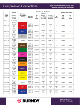
A.2 Supported Lugs for Termination
TABLE 6. INPUT CONNECTIONS APPLIES TO 01641010 AND 01641210
wiRe gauge suppoRted CoMM/net paRt # ManuFaCtuReR ManuFaCtuRe paRt # CRiMp die RequiRed
#1 AWG 538-298-10 Burndy YAZV1C2TC14FX Burndy, U1CRT-1, W1CRT1, W1CVT, X1CRT1
#0 AWG 538-243-10 Burndy YAZ252TC14 Burndy U2CABT, W25RT, W25VT, X25RT
#00 AWG 538-114-10 Burndy YAZV262TC14FX Burndy U26RT, W26RT, W26VT, X26RT
#000 AWG 538-297-10 Burndy YAZV272TC14FX Burndy U27RT, W27RT, W27VT, X27RT
#0000 AWG 538-124-10 Burndy YAV28L2ENT14FX Burndy U28RT, W28RT, W28VT, X28RT
350 kcmil 538-070-10 Burndy YAZ342NT38FX, Blue, 19 Burndy U32RT, W32RT, W32VT, Y81KFT
TAB LE 7. INPUT CONNECTIONS APPLIES TO 01645010, 01645110, AND 01645210
wiRe gauge suppoRted CoMM/net paRt # ManuFaCtuReR MaCtuFaCtuRe paRt # CRiMp die RequiRed
#1 AWG 538-021-10 Burndy YAZV1C2TC38FX Burndy U1CRT, W1CRT1, W1CVT, X1CRT1
#0 AWG 538-127-10 Burndy YAZV252TC38FX Burndy U25RT, W25RT, W25VT, X25RT
#00 AWG 538-099-10 Burndy YAZV262TC38FX Burndy U26RT, W26RT, W26VT, X26RT
#000 AWG 538-296-10 Burndy YAZV272TC38FX Burndy U27RT, W27RT, W27VT, X27RT
#0000 AWG 538-220-10 Burndy YAV28L2NT38FX Burndy U28RT, W28RT, W28VT, X28RT
350 kcmil 538-070-10 Burndy YAZ342NT38FX, Blue, 19 Burndy U32RT, W32RT, W32VT, Y81KFT
500 kcmil 538-131-10 Burndy YA38L2NT38FX Burndy U38XRT(2), Pink, L99
TABLE 8. OUTPUT CONNECTIONS APPLIES TO ALL MODELS
wiRe gauge suppoRted;
teRMinal type
CoMM/net paRt # ManuFaCtuReR ManuFaCtuRe paRt # CRiMp tool RequiRed
#16-14 AWG; Ring Terminal 538-068-10 TE Connectivity 34158 TE Connectivity 58433-3 with Die Assembly 58423-1
#10-12 AWG Ring Terminal 538-280-10 TE Connectivity 329697 TE Connectivity 169400 with Die Assembly 169404
#16-14 AWG; Spade Terminal 538-038-10 TE Connectivity 52955 TE Connectivity 58433-3 with Die Assembly 58423-1
#12-10 AWG; Spade Terminal 538-119-10 TE Connectivity 52961 TE Connectivity 58433-3 with Die Assembly 58423-1
#8 AWG 538-018-10 Burndy YAZ8C2TC14FX, Red, 49 Burndy U8CRT, W8CVT, W8CRT, X8CRT
#6 AWG 538-094-10 Burndy YAZV6C2TC14FX, Blue, 7 Burndy U5CRT, W5CVT, W5CRT, X5CRT
#6 AWG 538-165-10* Burndy YAZV6C2TC14FX90, Blue, 7 Burndy U5CRT, W5CVT, W5CRT, X5CRT
#4 AWG 538-085-10 Burndy YAZV4C2TC14FX, Gray, 8 Burndy U4CRT, W2CVT, W2CRT, X2CRT
#2 AWG 538-173-10 Burndy YAV2CL2NT14FX, Brown, 10 Burndy U2CRT, W4CVT, W4CRT, X4CRT
#2 AWG 538-275-10 Burndy YAV2CL2NT14FX90, Brown, 10 Burndy U2CRT, W4CVT, W4CRT, X4CRT
#2 AWG 538-284-10 Burndy YAZV2C2NT14FX90, Brown, 10 Burndy U2CRT, W4CVT, W4CRT, X4CRT
TABLE 9. GROUND LUG INFORMATION APPLIES TO 01641010 AND 01641210
wiRe gauge suppoRted CoMM/net paRt # ManuFaCtuReR ManuFaCtuRe paRt # CRiMp tool RequiRed
#6 AWG 538-094-10 Burndy YAZV6C2TC14FX Burndy U5CRT, W5CRT, W5CVT, X5CRT, Y1MRTC
#4 AWG 538-085-10 Burndy YAZV4C2TC14FX, Gray, 8 Burndy U2CRT, W4CVT, W4CRT, X4CRT
TABLE 10. GROUND LUG INFORMATION APPLIES TO 01645010, 01645110, 01645210,
wiRe gauge suppoRted CoMM/net paRt # ManuFaCtuReR ManuFaCtuRe paRt # CRiMp tool RequiRed
#2 AWG 538-089-10 Burndy YAZV2C2TC14FX, Brown, 10 Burndy U4CRT, W2CVT, W2CRT, X2CRT

HDX™
SETUP AND OPERATION MANUAL
PAGE 12 INSTALLATION
HDX™
SETUP AND OPERATION MANUAL
INSTALLATION PAGE 13
HDX™
SETUP AND OPERATION MANUAL
PAGE 12
HDX™
SETUP AND OPERATION MANUAL
PAGE 13
A1
A2
A3
A4
A5
A6
B1
B2
B3
B4
B5
B6
B
AM BREAKER
HOT -48V OUTPUTS
A SIDE OUTPUT RETURN +48V
B SIDE OUTPUT RETURN +48V
REAR VIEW
A INPUT DC HOT (-)
CONNECTION
B INPUT DC HOT (-)
CONNECTION
GLASTIC ISOLATOR BETWEEN
A AND B RETURN BUS BARS FOR
A/B INPUT VERSIONS. RETURN BUS
IS ELECTRICALLY ISOLATED A TO B.
B INPUT DC RETURN (+)
CONNECTION.
A INPUT DC RETURN (+)
CONNECTION.
A1
A2
A3
A4
B1
B2
B3
B4
C
D
DETAIL B
GMT FUSE
HOT OUTPUT
-48V
GMT FUSE
RETURN OUTPUT
+48V
6 - N.O.
5 - N.C.
4 - COM
3 - N.O.
2 - N.C.
1 - COM
DETAIL C
SET SCREW FORM "C"
ALARM CONTACTS.
SEE NOTE 1.
DETAIL D
RJ45 ALARM CONTACTS
JACKS ARE DAISY CHAINED
PIN DETAILS IN TABLE A.
SEE NOTE 1.
2 4 6 8 2 4 6 8
1 3 5 7
1 3 5 7
1 - COM
2 - N.C.
3 - N.O.
4 - COM
5 - N.C.
6 - N.O.
TABLE "A"
MAJOR
MINOR
(NOT USED)
NOTES:
CIRCUIT BREAKER TRIP AND FUSE FAIL ALARM
1.
AVAILABLE ON MAJOR ALARM CONTACTS.
Figure 10. Rear Detail HDX 300 A/B Isolated Input Model 016-410-10
MOUNTING BRACKET
SCREWS. REMOVE TO
ADJUST TO 23" DEPTH.
SEE SHEET 3 FOR MORE
DETAIL.
COUNTERSINK HARDWARE USED
FOR 19" CONFIGURATION. PANHEAD
HARDWARE USED FOR 23"
CONFIGURATION. ALL HARDWARE
INCLUDED
R
.141
TYP.
0
3.470
.235
3.235
A POWER INPUT LED
B POWER INPUT LED
BREAKER/FUSE TRIP LED
0
1.111
1.431
8.592
9.342
10.667
B SIDE HOT INPUT
-48V
A SIDE HOT INPUT
-48V
A SIDE OUTPUT
RETURNS +48V
B SIDE OUTPUT RETURNS
+48V
.625
.625
THREADED FOR 1/4-20 TYP.
B SIDE MAIN RETURN
CONNECTION.
CHASSIS GROUND
.625
.625
1/4-20 STUDS
1/4-20 STUDS
.760
.640
1.050
TYP.
0
1.763
3.013
16.032
17.000
12.232
11.226
0
.572
.961
1.271
2.283
3.470
A
RJ ALARM JACKS
SET SCREW ALARM CONNECTIONS
6-32 SET
SCREWS
THREADED FOR 3/8-16
DETAIL A
A RETURN +48V
B RETURN
+48V
A HOT -48V
B HOT -48V
MOUNTING BRACKET / REAR COVER DETAIL
REAR VIEW
Figure 9. Connection Detail HDX 300 A/B Isolated Input Model 016-410-10
Appendix B: Mechanical Illustrations

HDX™
SETUP AND OPERATION MANUAL
PAGE 14 INSTALLATION
HDX™
SETUP AND OPERATION MANUAL
INSTALLATION PAGE 15
HDX™
SETUP AND OPERATION MANUAL
PAGE 14
HDX™
SETUP AND OPERATION MANUAL
PAGE 15
MOUNTING BRACKET
SCREWS. REMOVE TO
ADJUST TO 23" DEPTH.
COUNTERSINK HARDWARE USED
FOR 19" CONFIGURATION. PANHEAD
HARDWARE USED FOR 23"
CONFIGURATION. ALL HARDWARE
INCLUDED
R
.141
TYP.
0
3.470
.235
3.235
POWER INPUT LED
BREAKER/FUSE TRIP LED
0
1.111
1.431
8.592
9.342
10.667
HOT INPUT
-48V
OUTPUT
RETURNS +48V
.625
.625
THREADED FOR 1/4-20 TYP.
MAIN RETURN
CONNECTION.
CHASSIS GROUND
.625
.625
1/4-20 STUDS
1/4-20 STUDS
.760
.640
1.050
TYP.
0
1.763
3.013
15.940
17.000
12.140
11.226
0
.572
.961
1.271
2.283
3.470
A
RJ ALARM JACKS
SET SCREW ALARM CONNECTIONS
6-32 SET
SCREWS
THREADED FOR 3/8-16
DETAIL A
RETURN +48V
HOT -48V
MOUNTING BRACKET / REAR COVER DETAIL
REAR VIEW
Figure 12. Connection Detail HDX 300 Single Input Model 016-412-10
18.047
18.359
3.000
R
.141
TYP.
22.047
22.359
3.000
R
.141
0
10.914
19" MOUNTING
BRACKETS
CABLES ACCESS
FOR A RETURN +48V
CABLES ACCESS
FOR B RETURN +48V
CABLES ACCESS FOR RJ STYLE ALARM.
DESIGNED AS A KNOCKOUT FEATURE.
CABLES ACCESS FOR A HOT -48V
CABLES ACCESS FOR B HOT -48V
CABLE ACCESSCABLE ACCESS
19" RACK MOUNT ORIENTATION
23" RACK MOUNT ORIENTATION
TOP VIEW WITH REAR COVER
BOTTOM VIEW WITH REAR COVER
Figure 11. Top and Bottom View HDX 300 A/B Isolated Input Model 016-410-10

HDX™
SETUP AND OPERATION MANUAL
PAGE 16 INSTALLATION
HDX™
SETUP AND OPERATION MANUAL
INSTALLATION PAGE 17
HDX™
SETUP AND OPERATION MANUAL
PAGE 16
HDX™
SETUP AND OPERATION MANUAL
PAGE 17
18.047
18.359
3.000
R
.141
TYP.
22.047
22.359
3.000
R
.141
0
10.914
19" MOUNTING
BRACKETS
CABLES ACCESS
FOR RETURN +48V
CABLES ACCESS
FOR RETURN +48V
CABLES ACCESS FOR RJ STYLE ALARM.
DESIGNED AS A KNOCKOUT FEATURE.
CABLES ACCESS FOR HOT -48V
CABLE ACCESSCABLE ACCESS
19" RACK MOUNT ORIENTATION
23" RACK MOUNT ORIENTATION
TOP VIEW WITH REAR COVER
BOTTOM VIEW WITH REAR COVER
Figure 14. Top and Bottom View HDX 300 Single Input Model 016-412-10
1
2
3
4
5
6
7
8
9
10
11
12
B
AM BREAKER
HOT -48V OUTPUTS
OUTPUT RETURN +48V
REAR VIEW
INPUT DC HOT (-)
CONNECTION
INPUT DC RETURN (+)
CONNECTION.
INPUT DC RETURN (+)
CONNECTION.
1
2
3
4
5
6
7
8
C
D
DETAIL B
GMT FUSE
HOT OUTPUT
-48V
GMT FUSE
RETURN OUTPUT
+48V
6 - N.O.
5 - N.C.
4 - COM
3 - N.O.
2 - N.C.
1 - COM
DETAIL C
SET SCREW FORM "C"
ALARM CONTACTS.
SEE NOTE 1.
DETAIL D
RJ45 ALARM CONTACTS
JACKS ARE DAISY CHAINED
PIN DETAILS IN TABLE A.
SEE NOTE 1.
2 4 6 8 2 4 6 8
1 3 5 7
1 3 5 7
1 - COM
2 - N.C.
3 - N.O.
4 - COM
5 - N.C.
6 - N.O.
TABLE "A"
MAJOR
MINOR
(NOT USED)
NOTES:
CIRCUIT BREAKER TRIP AND FUSE FAIL ALARM
1.
AVAILABLE ON MAJOR ALARM CONTACTS.
Figure 13. Rear Detail HDX 300 Single Input Model 016-412-10

HDX™
SETUP AND OPERATION MANUAL
PAGE 18 INSTALLATION
HDX™
SETUP AND OPERATION MANUAL
INSTALLATION PAGE 19
HDX™
SETUP AND OPERATION MANUAL
PAGE 18
HDX™
SETUP AND OPERATION MANUAL
PAGE 19
Figure 16. Rear Detail HDX 400 A/B Isolated Input Model 016-450-10
A
B INPUT DC RETURN (+)
CONNECTION.
B SIDE OUTPUT RETURN + 48 V
GLASTIC ISOLATOR BETWEEN
A AND B RETURN BUS BARS FOR
A/B INPUT VERSIONS. RETURN BUS
IS ELECTRICALLY ISOLATED A TO B
A SIDE OUTPUT RETURN + 48V
A INPUT DC RETURN (+)
CONNECTION.
B INPUT DC HOT (-)
CONNECTION
A INPUT DC HOT (-)
CONNECTION
DETAIL A
RJ45 ALARM CONTACTS
JACKS ARE DAISY CHAINED
PIN DETAILS IN TABLE A
SEE NOTE 1.
NOTES:
1. CIRCUIT BREAKER TRIP ALRAM
AVAILABLE ON MAJOR ALARM
CONTACTS.
1 - COM
2 - N.C.
3 - N.O.
4 - COM
5 - N.C.
6 - N.O.
TABLE "A"
MAJOR
MINOR
(NOT USED)
R.141 TYP.
0
.235
3.235
3.470
A POWER INPUT LED
B POWER INPUT LED
BREAKER TRIP LED
0
1.431
1.111
8.592
9.342
11.167
A SIDE OUTPUT
RETURNS +48V
B SIDE OUTPUT RETURNS
+48V
A SIDE HOT INPUT
-48V
B SIDE HOT INPUT
-48V
.625
.625
CHASSIS GROUND
B SIDE MAIN RETURN
CONNECTION
1/4-20 TYP
MOUNTING BRACKET/ REAR COVER DETAIL
COUNTERSUNK HARDWARE USED
FOR 19" CONFIGURATION. PANHEAD
HARDWARE USED FOR 23"
CONFIGURATION. ALL HARDWARE INCLUDED
MOUNTING BRACKET
SCREWS. REMOVE TO
ADJUST TO 23" DEPTH.
.760
.625
.625
.760
1.050
.640
1.000
1.050
17.000
1/4-20 STUDS 1/4-20 STUDS
RJ ALARM JACKS
Figure 15. Connection Detail HDX 400 A/B Isolated Input Model 016-450-10

HDX™
SETUP AND OPERATION MANUAL
PAGE 20 INSTALLATION
HDX™
SETUP AND OPERATION MANUAL
INSTALLATION PAGE 21
HDX™
SETUP AND OPERATION MANUAL
PAGE 20
HDX™
SETUP AND OPERATION MANUAL
PAGE 21
Figure 18. Connection Detail HDX 400 A/B Single Input Model 016-451-10
R.141 TYP.
0
.235
3.235
3.470
POWER INPUT LED
BREAKER TRIP LED
0
1.431
1.111
8.592
9.342
11.167
OUTPUT RETURNS
+48V
HOT INPUT
-48V
.625
.625
CHASSIS GROUND
MAIN RETURN
CONNECTION
1/4-20 TYP
MOUNTING BRACKET/ REAR COVER DETAIL
COUNTERSUNK HARDWARE USED
FOR 19" CONFIGURATION. PANHEAD
HARDWARE USED FOR 23"
CONFIGURATION. ALL HARDWARE INCLUDED
MOUNTING BRACKET
SCREWS. REMOVE TO
ADJUST TO 23" DEPTH.
.760
.625
.625
.760
1.050
.640
1.000
1.050
17.000
1/4-20 STUDS 1/4-20 STUDS
RJ ALARM JACKS
KNOCKOUT FEATURE CABLE ACCESS
0
11.464
CABLE ACCESS FOR
A AND B SIDE HOT -48V
DESIGNED AS A KNOCKOUT
FEATURE
CABLE ACCCESS
FOR A RETURN +48V
CABLE ACCCESS
FOR B RETURN +48V
BRACKETS
18.047
18.359
3.000
R.141 TYP
3.000
22.047
22.359
19" RACK MOUNT ORIENTATION
23" RACK MOUNT ORIENTATION
BOTTOM VIEW WITH REAR COVER
TOP VIEW WITH REAR COVER
Figure 17. Top and Bottom View HDX 400 A/B Isolated Input Model 016-450-10

HDX™
SETUP AND OPERATION MANUAL
PAGE 22 INSTALLATION
HDX™
SETUP AND OPERATION MANUAL
INSTALLATION PAGE 23
HDX™
SETUP AND OPERATION MANUAL
PAGE 22
HDX™
SETUP AND OPERATION MANUAL
PAGE 23
Figure 20. Top and Bottom View HDX 400 A/B Single Input Model 016-451-10
KNOCKOUT FEATURE CABLE ACCESS
0
11.464
CABLE ACCESS FOR
HOT -48V
DESIGNED AS A KNOCKOUT
FEATURE
CABLE ACCCESS
FOR RETURN +48V
CABLE ACCCESS
FOR RETURN +48V
BRACKETS
18.047
18.359
3.000
R.141 TYP
3.000
22.047
22.359
19" RACK MOUNT ORIENTATION
23" RACK MOUNT ORIENTATION
BOTTOM VIEW WITH REAR COVER
TOP VIEW WITH REAR COVER
Figure 19. Rear Detail HDX 400 A/B Single Input Model 016-451-10
A
DC RETURN (+)
CONNECTION.
OUTPUT RETURN + 48 V
OUTPUT RETURN + 48V
DC RETURN (+)
CONNECTION.
DC HOT (-)
CONNECTION
DETAIL A
RJ45 ALARM CONTACTS
JACKS ARE DAISY CHAINED
PIN DETAILS IN TABLE A
SEE NOTE 1.
NOTES:
1. CIRCUIT BREAKER TRIP ALRAM
AVAILABLE ON MAJOR ALARM
CONTACTS.
1 - COM
2 - N.C.
3 - N.O.
4 - COM
5 - N.C.
6 - N.O.
TABLE "A"
MAJOR
MINOR
(NOT USED)

HDX™
SETUP AND OPERATION MANUAL
PAGE 24 INSTALLATION
HDX™
SETUP AND OPERATION MANUAL
INSTALLATION PAGE 25
HDX™
SETUP AND OPERATION MANUAL
PAGE 24
HDX™
SETUP AND OPERATION MANUAL
PAGE 25
Figure 22. Top and Bottom View HDX A/B/C Diode Routed Input Model 016-452-10
KNOCKOUT FEATURE CABLE ACCESS
0
11.464
CABLE ACCESS FOR
A AND B SIDE HOT -48V
DESIGNED AS A KNOCKOUT
FEATURE
CABLE ACCCESS
C RETURN +48V
CABLE ACCCESS
C RETURN +48V
MOUNTING
BRACKETS
18.047
18.359
3.000
R.141 TYP
3.000
22.047
22.359
19" RACK MOUNT ORIENTATION
23" RACK MOUNT ORIENTATION
BOTTOM VIEW WITH REAR COVER
TOP VIEW WITH REAR COVER
Figure 21. Connection Detail HDX A/B/C Diode Routed input Model 016-452-10
17.000
.760
.640
1.050
1.000
.760
1/4-20 STUDS
1/4-20 STUDS
.625
.625
MAIN RETURN
CONNECTION
.625
.625
CHASSIS GROUND
1.431
1.111
0
R.141 TYP.
0
.235
3.235
3.470
11.167
8.592
9.342
C OUTPUT
RETURN
+48V
A HOT INPUT
-48V
A INPUT
POWER LED
B INPUT
POWER LED
BREAKER TRIP
LED
FORM C
DRY CONTACT
ALARM CONN.
B HOT INPUT
-48V

HDX™
SETUP AND OPERATION MANUAL
PAGE 26
THIS PAGE INTENTIONALLY LEFT BLANK
NOTES:

About Comm/net Systems
Comm/net Systems, Inc. (CSI) is the leader in high power density
communications power systems. Comm/net oers comprehensive
power and communications site systems integration and deployment
services via a national footprint of regional branch oces. Additional
information can be found at www.commnetsystems.com.
Corporate Headquarters
Comm/net Systems, Inc.
4237 – 24th Avenue West
Seattle, WA 98199
TEL: 206.282.8670
FAX: 206.282.8684
www.commnetsystems.com
24/7 Sales & Service
To purchase Comm/net Systems solutions, contact your
Comm/net Systems representative at: (800) 274-0544
or e-mail: sales@commnetsystems.com
© 2015 Comm/net Systems, Inc. All rights reserved. Comm/net Systems, and the Comm/net Systems logo are registered trademarks of Comm/net Systems, Inc. in the United States and other countries. All other
trademarks, service marks, registered marks, or registered service marks are the property of their respective owners. Comm/net Systems assumes no responsibility for any inaccuracies in this document. Comm/net
Systems reserves the right to change, modify, transfer, or otherwise revise this publication without notice.
Document Number: 048-693-30 | Revision Level: r02 | Published: June 2015
/