Page is loading ...

HDN
™
High Density Networked DC Distribution
Technical Manual
Effective: April 2020

2
C048-692-30 R07, Rev. C (04/2020)
The following sections contain important safety information that must be followed during the installation and maintenance
of the equipment and batteries. Read all of the instructions before installing or operating the equipment, and save this
manual for future reference.
There may be multiple warnings associated with the call out. Example:
ATTENTION provides specic regulatory/code requirements that may aect the placement of equipment and /or
installation procedures.
ATTENTION:
NOTICE provides additional information to help complete a specic task or procedure.
NOTICE:
ELECTRICAL HAZARD WARNING provides electrical safety information to PREVENT INJURY OR DEATH
to the technician or user.
WARNING! ELECTRICAL HAZARD
FUMES HAZARD WARNING provides fumes safety information to PREVENT INJURY OR DEATH to the
technician or user.
WARNING! FUMES HAZARD
FIRE HAZARD WARNING provides ammability safety information to PREVENT INJURY OR DEATH to the
technician or user.
WARNING! FIRE HAZARD
This WARNING provides safety information for both Electrical AND Fire Hazards
WARNING! ELECTRICAL & FIRE HAZARD
CAUTION provides safety information intended to PREVENT DAMAGE to material or equipment.
CAUTION!
GENERAL HAZARD WARNING provides safety information to PREVENT INJURY OR DEATH to the
technician or user.
WARNING! GENERAL HAZARD
Safety Notes
Alpha Technologies Services, Inc. considers customer safety and satisfaction its most important priority. To reduce the
risk of injury or death and to ensure continual safe operation of this product, certain information is presented dierently in
this manual. Alpha
®
tries to adhere to ANSI Z535 and encourages special attention and care to information presented in
the following manner:

3
C048-692-30 R07, Rev. C (04/2020)
HDN
™
High Density Networked DC Distribution
Technical Manual
C048-692-30 R07, Rev. C
Eective: April 2020
©
2020 by Alpha Technologies Services, Inc.
Disclaimer
Images contained in this manual are for illustrative purposes only. These images may not match your installation. Operator
is cautioned to review the drawings and illustrations contained in this manual before proceeding. If there are questions
regarding the safe operation of this powering system, please contact Alpha Technologies Services, Inc. or your nearest
Alpha representative.
Alpha shall not be held liable for any damage or injury involving its enclosures, power supplies, generators, batteries or
other hardware if used or operated in any manner or subject to any condition not consistent with its intended purpose or is
installed or operated in an unapproved manner or improperly maintained.
Contact Information
Sales information and customer service in USA
(7AM to 5PM, Pacic Time): 1 800 322 5742
Complete Technical Support in USA
(7AM to 5PM, Pacic Time or 24/7 emergency support): 1 800 863 3364
Sales information and Technical Support in Canada: 1 888 462 7487
Website: www.alpha.com

4
C048-692-30 R07, Rev. C (04/2020)
Contents
1.0 Purpose and Applicability � � � � � � � � � � � � � � � � � � � � � � � � � � � � � � � � � � � � � � � � � � � � � � � � � 6
1�1 Product Model � � � � � � � � � � � � � � � � � � � � � � � � � � � � � � � � � � � � � � � � � � � � � � � � � � � � � � � � � � � � � � � � � � � � 6
1�2 Firmware Version � � � � � � � � � � � � � � � � � � � � � � � � � � � � � � � � � � � � � � � � � � � � � � � � � � � � � � � � � � � � � � � � � � 6
2.0 Theory of Operation � � � � � � � � � � � � � � � � � � � � � � � � � � � � � � � � � � � � � � � � � � � � � � � � � � � � � � � 6
2�1 Introduction � � � � � � � � � � � � � � � � � � � � � � � � � � � � � � � � � � � � � � � � � � � � � � � � � � � � � � � � � � � � � � � � � � � � � � � 6
2�2 Features � � � � � � � � � � � � � � � � � � � � � � � � � � � � � � � � � � � � � � � � � � � � � � � � � � � � � � � � � � � � � � � � � � � � � � � � � 6
3.0 Unpacking and Inspection � � � � � � � � � � � � � � � � � � � � � � � � � � � � � � � � � � � � � � � � � � � � � � � � � 7
3�1 Package Contents � � � � � � � � � � � � � � � � � � � � � � � � � � � � � � � � � � � � � � � � � � � � � � � � � � � � � � � � � � � � � � � � � 7
4.0 Installation � � � � � � � � � � � � � � � � � � � � � � � � � � � � � � � � � � � � � � � � � � � � � � � � � � � � � � � � � � � � � � � � 7
4�1 Installation Preparation � � � � � � � � � � � � � � � � � � � � � � � � � � � � � � � � � � � � � � � � � � � � � � � � � � � � � � � � � � � � � � 7
4�1�1 Elevated Operating Ambient Temperature � � � � � � � � � � � � � � � � � � � � � � � � � � � � � � � � � � � � � � � � � � � 7
4�1�2 Reduced Air Flow � � � � � � � � � � � � � � � � � � � � � � � � � � � � � � � � � � � � � � � � � � � � � � � � � � � � � � � � � � � � � � 7
4�1�3 Mechanical Loading � � � � � � � � � � � � � � � � � � � � � � � � � � � � � � � � � � � � � � � � � � � � � � � � � � � � � � � � � � � � 7
4�1�4 Circuit Overloading � � � � � � � � � � � � � � � � � � � � � � � � � � � � � � � � � � � � � � � � � � � � � � � � � � � � � � � � � � � � 7
4�1�5 Reliable Earthing � � � � � � � � � � � � � � � � � � � � � � � � � � � � � � � � � � � � � � � � � � � � � � � � � � � � � � � � � � � � � � 7
4�1�6 Disconnect Device � � � � � � � � � � � � � � � � � � � � � � � � � � � � � � � � � � � � � � � � � � � � � � � � � � � � � � � � � � � � � 7
4�2 Mounting � � � � � � � � � � � � � � � � � � � � � � � � � � � � � � � � � � � � � � � � � � � � � � � � � � � � � � � � � � � � � � � � � � � � � � � � � 8
4�3 Chassis Ground � � � � � � � � � � � � � � � � � � � � � � � � � � � � � � � � � � � � � � � � � � � � � � � � � � � � � � � � � � � � � � � � � � � 8
4�4 Input Connections � � � � � � � � � � � � � � � � � � � � � � � � � � � � � � � � � � � � � � � � � � � � � � � � � � � � � � � � � � � � � � � � � � 9
4�5 Alarm Connections � � � � � � � � � � � � � � � � � � � � � � � � � � � � � � � � � � � � � � � � � � � � � � � � � � � � � � � � � � � � � � � � � 9
4�6 Output Connections � � � � � � � � � � � � � � � � � � � � � � � � � � � � � � � � � � � � � � � � � � � � � � � � � � � � � � � � � � � � � � � 10
4�7 Rear Safety Cover Installation � � � � � � � � � � � � � � � � � � � � � � � � � � � � � � � � � � � � � � � � � � � � � � � � � � � � � � � 10
4�8 Installing Circuit Breakers � � � � � � � � � � � � � � � � � � � � � � � � � � � � � � � � � � � � � � � � � � � � � � � � � � � � � � � � � � � 11
5.0 Operation � � � � � � � � � � � � � � � � � � � � � � � � � � � � � � � � � � � � � � � � � � � � � � � � � � � � � � � � � � � � � � � � � 11
5�1 How to Review System Status via Display LEDs � � � � � � � � � � � � � � � � � � � � � � � � � � � � � � � � � � � � � � � � � 11
5�1�1 Power Input A � � � � � � � � � � � � � � � � � � � � � � � � � � � � � � � � � � � � � � � � � � � � � � � � � � � � � � � � � � � � � � � � 11
5�1�2 Power Input B � � � � � � � � � � � � � � � � � � � � � � � � � � � � � � � � � � � � � � � � � � � � � � � � � � � � � � � � � � � � � � � 11
5�1�3 Alarm � � � � � � � � � � � � � � � � � � � � � � � � � � � � � � � � � � � � � � � � � � � � � � � � � � � � � � � � � � � � � � � � � � � � � � 11
6.0 Supervisory Controller � � � � � � � � � � � � � � � � � � � � � � � � � � � � � � � � � � � � � � � � � � � � � � � � � � � �12
6�1 Home Screen Information � � � � � � � � � � � � � � � � � � � � � � � � � � � � � � � � � � � � � � � � � � � � � � � � � � � � � � � � � � � 12
6�1�1 Home Screens - Single Input Models � � � � � � � � � � � � � � � � � � � � � � � � � � � � � � � � � � � � � � � � � � � � � 12
6�1�2 Home Screens - Dual Input Models � � � � � � � � � � � � � � � � � � � � � � � � � � � � � � � � � � � � � � � � � � � � � � � 12
6�2 Initial Operation � � � � � � � � � � � � � � � � � � � � � � � � � � � � � � � � � � � � � � � � � � � � � � � � � � � � � � � � � � � � � � � � � � 12
6�2�1 Breaker Inventory � � � � � � � � � � � � � � � � � � � � � � � � � � � � � � � � � � � � � � � � � � � � � � � � � � � � � � � � � � � � � 12
6�2�2 Set Breaker Ampacity � � � � � � � � � � � � � � � � � � � � � � � � � � � � � � � � � � � � � � � � � � � � � � � � � � � � � � � � � 12
6�2�3 Warning and Alarm Threshold � � � � � � � � � � � � � � � � � � � � � � � � � � � � � � � � � � � � � � � � � � � � � � � � � � � 13
6�2�4 Set Date/Time and Data Log � � � � � � � � � � � � � � � � � � � � � � � � � � � � � � � � � � � � � � � � � � � � � � � � � � � � 13
6�3 Main Menu � � � � � � � � � � � � � � � � � � � � � � � � � � � � � � � � � � � � � � � � � � � � � � � � � � � � � � � � � � � � � � � � � � � � � � 13
6�3�1 Alarm/Warnings Menu � � � � � � � � � � � � � � � � � � � � � � � � � � � � � � � � � � � � � � � � � � � � � � � � � � � � � � � � � 13
6�3�2 History � � � � � � � � � � � � � � � � � � � � � � � � � � � � � � � � � � � � � � � � � � � � � � � � � � � � � � � � � � � � � � � � � � � � � 13
6�3�3 Breaker Detail � � � � � � � � � � � � � � � � � � � � � � � � � � � � � � � � � � � � � � � � � � � � � � � � � � � � � � � � � � � � � � � 13
6�4 Settings � � � � � � � � � � � � � � � � � � � � � � � � � � � � � � � � � � � � � � � � � � � � � � � � � � � � � � � � � � � � � � � � � � � � � � � � � 13
6�4�1 System Settings � � � � � � � � � � � � � � � � � � � � � � � � � � � � � � � � � � � � � � � � � � � � � � � � � � � � � � � � � � � � � � 13
6�4�2 Breaker Settings � � � � � � � � � � � � � � � � � � � � � � � � � � � � � � � � � � � � � � � � � � � � � � � � � � � � � � � � � � � � � 13
6�4�3 Calibration Settings � � � � � � � � � � � � � � � � � � � � � � � � � � � � � � � � � � � � � � � � � � � � � � � � � � � � � � � � � � � 14
6�4�4 Advanced Settings � � � � � � � � � � � � � � � � � � � � � � � � � � � � � � � � � � � � � � � � � � � � � � � � � � � � � � � � � � � � 14

5
C048-692-30 R07, Rev. C (04/2020)
6�5 Operating Conditions � � � � � � � � � � � � � � � � � � � � � � � � � � � � � � � � � � � � � � � � � � � � � � � � � � � � � � � � � � � � � � 14
6�5�1 Normal Condition � � � � � � � � � � � � � � � � � � � � � � � � � � � � � � � � � � � � � � � � � � � � � � � � � � � � � � � � � � � � � 14
6�5�2 Warning Condition � � � � � � � � � � � � � � � � � � � � � � � � � � � � � � � � � � � � � � � � � � � � � � � � � � � � � � � � � � � � 14
6�5�3 Alarm Conditions � � � � � � � � � � � � � � � � � � � � � � � � � � � � � � � � � � � � � � � � � � � � � � � � � � � � � � � � � � � � � 15
6�6 How to Review System Status via the Embedded Webserver � � � � � � � � � � � � � � � � � � � � � � � � � � � � � � � 16
6�6�1 Default Static Network Settings � � � � � � � � � � � � � � � � � � � � � � � � � � � � � � � � � � � � � � � � � � � � � � � � � � 16
6�7 Navigating the Webserver � � � � � � � � � � � � � � � � � � � � � � � � � � � � � � � � � � � � � � � � � � � � � � � � � � � � � � � � � � 16
7.0 Product Specications � � � � � � � � � � � � � � � � � � � � � � � � � � � � � � � � � � � � � � � � � � � � � � � � � � � �17
8.0 Models and Accessories � � � � � � � � � � � � � � � � � � � � � � � � � � � � � � � � � � � � � � � � � � � � � � � � � �18
Appendix A: Mechanical Drawings . . . . . . . . . . . . . . . . . . . . . . . . . . . . . . . . . . . . . 20
A�1 HDN 300 Single Input BDFB Version (C016-1660-10) � � � � � � � � � � � � � � � � � � � � � � � � � � � � � � � � � � � � 20
A�2 HDN 300 Single Input (C016-1661-10) � � � � � � � � � � � � � � � � � � � � � � � � � � � � � � � � � � � � � � � � � � � � � � � � 21
A�3 HDN 300 Dual Input (C016-1662-10) � � � � � � � � � � � � � � � � � � � � � � � � � � � � � � � � � � � � � � � � � � � � � � � � � � 22
A�4 HDN 600 Single Input BDFB Version (C016-1720-10) � � � � � � � � � � � � � � � � � � � � � � � � � � � � � � � � � � � � 23
A�5 HDN 600 Single Input (C016-1721-10) � � � � � � � � � � � � � � � � � � � � � � � � � � � � � � � � � � � � � � � � � � � � � � � � 24
A�6 HDN 600 Dual Input (C016-1722-10) � � � � � � � � � � � � � � � � � � � � � � � � � � � � � � � � � � � � � � � � � � � � � � � � � � 25

6
C048-692-30 R07, Rev. C (04/2020)
1.0 1.0 Purpose and Applicability Purpose and Applicability
The purpose of this document is to detail the installation and
operation instructions for the HDN 300/600 High Density DC
Distribution Center�
1.1 1.1 Product ModelProduct Model
This document applies to the following congurations of the HDN
Compact DC Power Distribution Center:
Table 1. HDN Model Congurations
PART NUMBER DESCRIPTION
C016-1660-10 HDN 300; Single Input BDFB Version (No Return Bar); 22 AM Breaker Positions; UL1801
C016-1661-10 HDN 300; Single Input; 22 AM Breaker Positions; UL1801
C016-1662-10 HDN 300; Dual Isolated (A/B) Input; 11A/11B AM Breaker Positions; UL1801
C016-1720-10 HDN 600; Single Input BDFB Version (No Return Bar); 22 AM Breaker Positions; UL1801
C016-1721-10 HDN 600; Single Input; 22 AM Breaker Positions; UL1801
C016-1722-10 HDN 600; Dual Isolated (A/B) Input; 11A/11B AM Breaker Positions; UL1801
1.2 1.2 Firmware VersionFirmware Version
This document applies to the following product rmware version(s):
y 034-033-34 HDN Supervisory Controller r01 and newer
For legacy rmware support, contact Alpha support.
2.0 2.0 Theory of OperationTheory of Operation
2.1 2.1 IntroductionIntroduction
The HDN is an advanced, high-density DC distribution center for
rack-mount telecom and broadband applications� Its robust design
distributes power for up to 22 loads� The advanced supervisory
control allows local and remote monitoring of not only breaker
status, but of individual load current, and input bus current.
2.2 2.2 FeaturesFeatures
y High-Reliability, High-Density Breaker Distribution
y Dual Isolated Power Inputs or Single Input versions
y 600A Maximum Total Load
y 22 AM Breaker Positions
y 100A Max per Breaker Position
y Intuitive Touchscreen Interface
y RGB Backlight and Bright LEDs Indicate Status at a Glance
y Current Monitoring Per Output
y Form C Alarm Contacts
y Optional Ethernet Module with Integrated Web Interface and
SNMP Support ( V�1 and V� 2)
y Adjustable brackets for 19 in� or 23 in� rack mount installation

7
C048-692-30 R07, Rev. C (04/2020)
3.0 3.0 Unpacking and InspectionUnpacking and Inspection
The HDN 300/600 High Density DC Distribution Center was carefully packaged at the factory to
withstand the normal rigors of shipping. However, you should carefully inspect the box and contents to
conrm that no damage has occurred in transit. Most shipping carriers require notication of shipping
damage within twenty-four hours of delivery, and it is the responsibility of the recipient to inspect the
shipment immediately upon receipt�
3.1 3.1 Package ContentsPackage Contents
Included with your product are the following items:
y HDN Distribution Panel
y Mounting hardware kit with necessary bolts and washers
y Rear plastic bus bar safety shield
4.0 4.0 InstallationInstallation
The HDN panel can be installed in any standard 19-inch or 23-inch relay rack� The panel itself occupies
only 3RU, but it is recommended that space be left free above and below the panel to ease cable routing.
It is common to mount the HDN panel at the topmost rack position�
4.1 4.1 Installation PreparationInstallation Preparation
When selecting an installation location, ensure that all of the following conditions are met before
proceeding�
4.1.1 4.1.1 Elevated Operating Ambient TemperatureElevated Operating Ambient Temperature
If you install the panel in a closed or multi-unit rack assembly, the operating ambient temperature of the
rack environment may be greater than room ambient. Therefore, take care to install the equipment in an
environment compatible with the maximum ambient temperature (TMA)�
4.1.2 4.1.2 Reduced Air FlowReduced Air Flow
Installation of the equipment in a rack should be such that the amount of air ow required for safe
operation of the equipment is not compromised.
4.1.3 4.1.3 Mechanical LoadingMechanical Loading
Mounting of the equipment in the rack should be such that a hazardous condition is not achieved due to
uneven mechanical loading�
4.1.4 4.1.4 Circuit OverloadingCircuit Overloading
Give consideration to the connection of the equipment to the supply circuit and the eect that overloading
of the circuits might have on overcurrent protection and supply wiring� Use appropriate consideration for
equipment nameplate ratings when addressing this concern.
4.1.5 4.1.5 Reliable EarthingReliable Earthing
Maintain reliable earthing of rack-mounted equipment. Pay particular attention to supply connections
other than direct connections to the branch circuit (e.g., use of power strips).
4.1.6 4.1.6 Disconnect DeviceDisconnect Device
A readily accessible disconnect device must be incorporated in the building installation wiring�

8
C048-692-30 R07, Rev. C (04/2020)
4.2 4.2 MountingMounting
THIS PRODUCT MUST BE INSTALLED WITHIN A
RESTRICTED ACCESS LOCATION WHERE ACCESS IS
THROUGH THE USE OF A TOOL, LOCK AND KEY, OR
OTHER MEANS OF SECURITY, AND IS CONTROLLED
BY THE AUTHORITY RESPONSIBLE FOR THE
LOCATION� THIS PRODUCT MUST BE INSTALLED AND
MAINTAINED ONLY BY QUALIFIED TECHNICIANS.
NOTICE:
The HDN can be mounted in a front ush mount conguration or a
mid-mount conguration. Depending on the desired conguration,
attach the mounting ears accordingly�
Step 1. Orient the rack mount ears appropriately for a 19 or 23 inch
rack�
Step 2. For ush mounting, install the rack mount ears using the
included Phillips head screws through the two holes near the
front of the panel. For mid-mount conguration, use the two
holes further back on the sides of the panel�
Step 3. Insert the panel into the rack and attach with included #12-24
rack screws�
4.3 4.3 Chassis GroundChassis Ground
DO NOT ENERGIZE THE PANEL BEFORE CHASSIS
GROUND IS CONNECTED�
CAUTION!
The chassis ground is located on the side of the panel� A two hole
lug landing position is provided� See table below for termination
information. A minimum of #6 AWG chassis ground cable is required.
IMPORTANT: Grounding hardware not included. A properly-sized
grounding conductor must be installed per NEC (250�122)�
Table 2. Ground Termination Summary
TERMINATION
TYPE
HOLE/
STUD SIZE
CENTER
TO
CENTER
RECOMMENDED
TORQUE VALUE
Threaded Insert 1/4 in� 5/8 in� 100 in∙lbs
Step 1. Connect the lug to the chassis with 1/4 in� hardware� Make
sure heat shrink and no-oxide compound are applied
appropriately prior to attachment�
Step 2. Torque the fasteners to 100 in∙lbs�
Figure 1. Mounting Ears (19 in. shown)
Figure 2. Chassis Ground Connection

9
C048-692-30 R07, Rev. C (04/2020)
4.4 4.4 Input ConnectionsInput Connections
WARNING! ELECTRICAL HAZARD
MULTIPLE POWER SOURCES ARE PRESENT, ENSURE
ALL INPUT POWER FEEDS ARE NOT ENERGIZED
BEFORE INSTALLING THEM� ELECTRICAL
INSTALLATION SHOULD ONLY BE PERFORMED BY
QUALIFIED PERSONNEL WITH PROPER TOOLS AND
PROTECTIVE SAFETY EQUIPMENT.
USE ONLY THE 3/8"-16 X 1" BOLTS, SPLIT WASHERS
AND FLAT WASHERS PROVIDED. USE OF ANY OTHER
HARDWARE MAY DAMAGE THE PANEL.
MAKE SURE THAT ALL FEEDER CABLES HAVE HEAT
SHRINK APPLIED PRIOR TO TERMINATION, AND THAT
NO-OXIDE COMPOUND IS APPLIED TO ALL COPPER-
TO-COPPER CONNECTIONS�
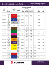
SEE SECTION 8 ON PAGE 18 FOR COMPRESSION
LUG SPECIFICATIONS, TOOLING, AND ORDERING
INFORMATION�
NOTICE:
Table 3. Input Termination Information
TERMINATION
TYPE
HOLE/
STUD
SIZE
CENTER TO
CENTER
RECOMMENDED
TORQUE VALUE
Through Hole 1/4 in� Slotted;
5/8 in� - 1 in�
350 in∙lbs
Step 1. Install a piece of clear heat shrink tubing (3" diameter x 6"
long) over each of the power cables prior to bolting the cable
lugs to the bus bars�
Step 2. Connect the incoming DC feeder cables for the A and B
power inputs and A and B power returns for the A/B isolated
panel� For a single input panel there will be one power input
and one return bus bar� Secure the cable lugs to the bus bars
with the included 3/8 in. x 1 in. bolts, at washers and lock
washers� The bus bars support lugs with 5/8 in� or 1 in� hole
spacing. Recommended Grade 5 Torque Value: 350 in·lbs
4.5 4.5 Alarm ConnectionsAlarm Connections
The HDN features two 8p8c modular jacks (RJ-45) for alarm
connections on the rear of the panel� The alarm contact pinout is
below:
Table 4. Alarm Contact Pinout
PIN 1 PIN 2 PIN 3 PIN 4-8
COM NC NO Reserved
The two jacks allow for easy daisy-chaining with UTP patch cables� If
daisy-chaining, the NO (normally open) condition must be monitored�

10
C048-692-30 R07, Rev. C (04/2020)
4.6 4.6 Output ConnectionsOutput Connections
DO NOT PERFORM THIS STEP ON CIRCUITS WITH
BREAKERS INSTALLED. ENSURE NO POWER IS
PRESENT ON THE CIRCUIT BEING WIRED BEFORE
PROCEEDING�
CAUTION!
MAKE SURE THAT ALL CABLES HAVE
INSULATED TERMINALS OR HEAT SHRINK
APPLIED PRIOR TO TERMINATION, AND THAT
NO-OXIDE COMPOUND IS APPLIED TO ALL
COPPER-TO-COPPER CONNECTIONS�
SEE SECTION 8 ON PAGE 18 FOR COMPRESSION
LUG SPECIFICATIONS, TOOLING, AND
ORDERING INFORMATION�
NOTICE:
Table 5. Output Termination Information
TERMINATION
TYPE
HOLE/
STUD
SIZE
CENTER
TO
CENTER
RECOMMENDED
TORQUE VALUE
Threaded Stud 1/4 in� 5/8 in� 100 in∙lbs
Step 1. Land the return cable lug to its corresponding position on the
return bus bar, then land the hot cable lug to the
corresponding position below�
4.7 4.7 Rear Safety Cover InstallationRear Safety Cover Installation
WARNING! ELECTRICAL HAZARD
FAILURE TO INSTALL THE PLASTIC SAFETY SHIELDS
PROPERLY MAY CREATE AN ELECTRICAL HAZARD.
THE PANEL MAY BE ENERGIZED WHEN INSTALLING
THE REAR PLASTIC SAFETY COVERS.
The HDN includes a rear safety cover which is to be installed
around the rear electrical terminations� The cable knockout points
in the plastic will need to be trimmed to match your input/output
cable conguration. Once this has been completed, proceed to the
following steps:
Step 1. Install the included #8-32 panhead screws into the threaded
holes on the sides of the panel�
Step 2. Slide the cover onto the screws installed, then tighten down
the screws to secure the cover�

11
C048-692-30 R07, Rev. C (04/2020)
4.8 4.8 Installing Circuit BreakersInstalling Circuit Breakers
SEE SECTION 8 ON PAGE 18 FOR CIRCUIT
BREAKER ORDERING INFORMATION.
NOTICE:
Step 1. Turn the captive mounting screws counterclockwise and lift
the front panel�
Step 2. Slide a circuit breaker of sucient ampacity into the position
corresponding to the output channel to be fed�
NOTE: When viewing from the front of the panel, from left to right,
the lower channel positions begin on the left and are counted
upwards as you move right�
WARNING! ELECTRICAL HAZARD
ENSURE THAT CIRCUIT BREAKERS ARE ORIENTED
SUCH THAT THE "ON" POSITION IS AT THE TOP.
Step 3. Push all installed circuit breakers rmly to ensure the
terminals are fully seated in their sockets�
5.0 5.0 OperationOperation
5.1 5.1 How to Review System Status via Display How to Review System Status via Display
LEDsLEDs
The HDN features bright front panel LEDs that allow for the overall
panel status to be determined at a glance�
5.1.1 5.1.1 Power Input APower Input A
This LED will illuminate BLUE when power is present on the A input�
5.1.2 5.1.2 Power Input BPower Input B
This LED will illuminate BLUE when power is present on the B input�
5.1.3 5.1.3 AlarmAlarm
This LED will illuminate RED if a breaker has tripped or if any other
alarm condition exists� Under normal conditions this light is not
illuminated�

12
C048-692-30 R07, Rev. C (04/2020)
6.0 6.0 Supervisory ControllerSupervisory Controller
The HDN panel uses a touchscreen user interface� Interact with the
touchscreen by using your ngertip, a stylus, or a capped pen to touch
the display and select status information, or to access the menu. In
addition to the status LEDs, the backlight of the LCD will change color
based on the status of the panel (see 6�5 Operating Conditions on
Page 14)�
6.1 6.1 Home Screen InformationHome Screen Information
The home screen displays input bus voltage, input bus current,
inventoried breakers, and alarm conditions. There are multiple home
screens depending on which HDN model is installed (see below)�
Touch any item on the home screen to access their submenus and
displays� Touch the main display area to cycle between home screens�
6.1.1 6.1.1 Home Screens - Single Input ModelsHome Screens - Single Input Models
1� Input Voltage & Bus Load with a bar graph displaying total load
(see Figure 3)�
2� Bar graphs showing the total load of all 22 breaker channels�
Breakers which are inventoried will be shaded on the bottom of
the display (see Figure 4)�
6.1.2 6.1.2 Home Screens - Dual Input ModelsHome Screens - Dual Input Models
1� Input Voltage & Bus Load for A & B inputs�
2� Bar graph of the A & B total load�
3� Bar graphs showing the total load of all 22 breaker channels�
Breakers which are inventoried will be shaded on the bottom of
the display�
6.2 6.2 Initial OperationInitial Operation
6.2.1 6.2.1 Breaker InventoryBreaker Inventory
IMPORTANT: Make sure that all breakers to be inventoried are turned
"ON".
Step 1. From the Home Screen, go to the Breakers menu (Settings >
Breakers)�
Step 2. Select "Take Inventory". All installed and active breakers will be
displayed� Follow the on-screen prompts to complete the
inventory process (see Figure 5)�
6.2.2 6.2.2 Set Breaker AmpacitySet Breaker Ampacity
From the Breaker menu (Settings > Breakers), set the breaker
ampacity by tapping on any of the three number boxes to change the
number. The default set ampacity is 100A, which is also the maximum
ampacity for an installed single-pole breaker (see Figure 6)� 2-pole
breakers can be adjusted to a maximum of 200A, and 3-pole breakers
support a maximum of 300A. To toggle the number of breaker poles,
tap the numbered breaker position on the screen� The display will
change to indicate the set number of poles, and which positions are
occupied. See Figure 7, which displays circuits B03-05 managed by a
3-pole breaker� NOTE: The position of a multi-pole breaker will be the
furthest left position occupied (for example, if a breaker occupies A02-
04, the breaker will be identied as Breaker A02).
Figure 3. Home Screen - HDN Single Input
Figure 4. Bar Graph Home Screen - HDN
Single Input
Figure 5. Breaker Inventory
Figure 6. Setting Breaker Ampacity
Figure 7. Setting a Multi-Pole Breaker

13
C048-692-30 R07, Rev. C (04/2020)
6.2.3 6.2.3 Warning and Alarm ThresholdWarning and Alarm Threshold
From the Breaker menu (Settings > Breakers), set the alarm threshold
to any value between 75% and 100% (see Figure 8)� This is the
amount of breaker utilization which will trigger an overcurrent alarm.
A local warning will be sent at 10% less than the set alarm threshold�
The default is 80%�
NOTE: This threshold is congured by default to monitor as a
redundant panel� It sums the current between the corresponding A
and B side outputs�
6.2.4 6.2.4 Set Date/Time and Data LogSet Date/Time and Data Log
Access the Data Log menu (Settings > Advanced > Data Log) and
select "Date/Time". You can also set the rate in which data is collected
on the SD card� The default rate is every 15 minutes� To change the
collection rate, go to the Data Log and select "Set Rate".
NOTE: If these actions are not performed, data will not be stored on
the SD card�
6.3 6.3 Main MenuMain Menu
6.3.1 6.3.1 Alarm/Warnings MenuAlarm/Warnings Menu
The color of the screen indicates the condition of the panel at a glance�
A red screen indicates a critical alarm is present, and orange indicates
a warning condition� An alarm icon will be present for both alarm and
warning conditions. Press this icon to access the alarm logs, review
logs, and to silence the audible alarm locally (see Figure 9)�
6.3.2 6.3.2 HistoryHistory
From the History menu, data on voltage and current for busses and
individual channels can be accessed (see Figure 10)�
6.3.3 6.3.3 Breaker DetailBreaker Detail
Shows detailed information about each channel� Cycle through the
breakers by touching the left and right arrows on the screen (see
Figure 11)�
6.4 6.4 SettingsSettings
6.4.1 6.4.1 System SettingsSystem Settings
The following settings are congured in Systems Settings:
y Redundant Monitor (Yes or No, Default Yes)
y Firmware Number Display (on second page)
y Default Home Screen
y Preferred Bar Graph units (Percent Full Load, or Load in Amps)
6.4.2 6.4.2 Breaker SettingsBreaker Settings
y Take Inventory
y Set Breakers (Set channel ampacity, default is 100A)
y % Alarm Threshold (Warning threshold is -10% from alarm
threshold� Default alarm threshold is 80%)
Figure 8. Breaker Settings Menu
Figure 9. Alarm Condition
Figure 10. History
Figure 11. Breaker Detail

14
C048-692-30 R07, Rev. C (04/2020)
6.4.3 6.4.3 Calibration SettingsCalibration Settings
IMPORTANT: DO NOT adjust any Calibration Settings without direct
instruction from Alpha Technologies�
6.4.4 6.4.4 Advanced SettingsAdvanced Settings
y Memory
y Settings - Clear settings to factory default� IMPORTANT:
Do not perform this function without direction from Alpha
Personnel!
y Calibration - Clears calibration� IMPORTANT: Do not
perform this function without direction from Alpha Personnel!
y EEPROM - This clears the EEPROM� IMPORTANT: Do not
perform this function without direction from Alpha Personnel!
y SD Card - This clears the memory from the on-board SD
card�
y Display - Allows calibration of display settings such as contrast
and touch calibration�
y Test Modes - Contains various test settings such as breaker trip
and alarm testing which can be useful during installation or for
troubleshooting�
y Data Log
y Set Date and Time (NOTE: If Date/Time is not set, data will
not be recorded to the SD card)
y Set Data Sample Rate (Default is every 15 min)
6.5 6.5 Operating ConditionsOperating Conditions
The HDN Supervisory Controller features colored backlit displays,
graphic icons and audible alarms to indicate its current operating
condition(s)�
6.5.1 6.5.1 Normal ConditionNormal Condition
A blue screen indicates normal operating conditions�
6.5.2 6.5.2 Warning ConditionWarning Condition
A warning condition will only be visible locally and will not cause an
alarm contact closure or trigger an SNMP trap� It is denoted on the
Supervisory Controller display by an orange screen and the presence
of the Alarm/Warning symbol in the upper left hand corner of the
home screen (see Figure 12)�
Please note that the bus and channel names given below may dier
depending on the bus(ses) and/or channel(s) being aected.
NOTE: For multi-pole breakers, the warning condition will show for
the primary position (Example: If a two-pole breaker in positions
A02-A03 is in warning, then a warning alarm will show for position
A02)
Breaker Overload | A1
This warning will occur when a channel is 10% below the set channel
over-current threshold. This threshold is congured in the breaker
settings menu (see 6�4�2 Breaker Settings on Page 13)�
Figure 12. Warning Condition

15
C048-692-30 R07, Rev. C (04/2020)
A-B Redundant Warn
This warning indicates that the summed load of busses A and B
and are approaching the over-current threshold for one bus� This
warning occurs at 10% below the bus over-current threshold�
NOTE: This alarm only occurs when the redundant monitoring
feature is enabled� Redundant monitoring is enabled by default (see
6�4�1 System Settings on Page 13)�
A1-B1 Redundant Warn
This warning indicates that the summed load of two redundant
channels has reached over-current threshold� Redundant channels
are channels with the same number value, such as A1 and B1 in a
dual input panel, or corresponding channels in paired single input
panels�
This threshold can be congured in the breaker setting menu (see
6�4�1 System Settings on Page 13)�
Current Sensor Fail
This warning indicates there is an issue with an internal sensor or
its circuitry� Try to reset the controller using the reset switch on the
left-hand side of the controller. If the warning persists, contact Alpha
support for more information and diagnostic steps�
IMPORTANT: Resetting the controller will reset the clock� If you do
this, be sure to set the date/time again (see 6�4�4 Advanced Settings
on Page 14 for information on setting the date/time)�
6.5.3 6.5.3 Alarm ConditionsAlarm Conditions
A red screen indicates that one of the following alarm conditions
are present� These are critical alarm conditions that will annunciate
locally as well as trigger alarm contact closures and trigger SNMP
traps�
Breaker Trip
Occurs if any inventoried breaker trips for any reason�
NOTE: For multi-pole breakers, a breaker trip alarm will show for
all occupied positions (Example: If a two-pole breaker in positions
A02-A03 is in breaker trip alarm, then an alarm will show for
positions A02 and A03)
Non-Inventoried Breaker
Occurs if a breaker is turned on and is not inventoried. To x this,
perform a breaker inventory to add all active channels to inventory
(see 6�2�1 Breaker Inventory on Page 12)�
Bus Overcurrent
Occurs when a bus exceeds its current alarm threshold� The
threshold is set to 80% by default�
High Input Voltage
Alarm is triggered when input voltage exceeds 56V�
Low Input voltage
Alarm is triggered when input voltage drops below 47V�

16
C048-692-30 R07, Rev. C (04/2020)
6.6 6.6 How to Review System Status via the How to Review System Status via the
Embedded WebserverEmbedded Webserver
The optional embedded ethernet module provides remote monitoring
via IP-based ethernet networks and a web browser� To view the
system status, you will need to connect the ethernet port on the rear
of your HDN to your network�
By default, the ethernet module is congured at the factory with a
static IP address and network settings, dened below. Use these
settings to set up a local network to communicate with the embedded
webserver� Enter the static IP address into a web browser:
y 192.168.123.123
Once you establish a connection to the embedded ethernet module,
use the following credentials to gain access to the protected data and
administrative pages:
y Username: root
y Password: password
6.6.1 6.6.1 Default Static Network SettingsDefault Static Network Settings
Use these settings to set up a local network to communicate with the
embedded webserver� Enter the static IP address into a web browser�
y IPV4 Address: 192�168�123�123
y Subnet Mask: 255�255�255�0
y Default Gateway: 192�16 8�123�1
y Default DNS: 192�16 8�123�1
y Secondary DNS: 8�8�8�8
6.7 6.7 Navigating the WebserverNavigating the Webserver
Once you access the webserver you will be able to review the status
of the HDN panel. You can also access and change notication,
network, and other settings via the Administration Settings tab.

17
C048-692-30 R07, Rev. C (04/2020)
7.0 7.0 Product SpecicationsProduct Specications
Table 6. Technical Specications Per Model
C016-1660-10
(HDN 300)
C016-1661-10
(HDN 300)
C016-1662-10
(HDN 300)
C016-1720-10
(HDN 600)
C016-1721-10
(HDN 600)
C016-1722-10
(HDN 600)
Type of Input Single Input Single Input A/B Isolated
Input
Single Input Single Input A/B Isolated
Input
Circuits 22 22 22 (11A /11B) 22 22 22 (11A /11B)
Input Voltage -48VDC -48VDC -48VDC -48VDC -48VDC -48VDC
Input Current 300A Max 300A Max 300A Max 600A Max 600A Max 600A Max
Maximum AM Breaker
Size
100A 100A 100A 100A 100A 100A
Maximum per Circuit
Current
(AM Breaker)
100A 100A 100A 100A 100A 100A
Max Operating
Altitude
2000m 2000m 2000m 2000m 2000m 2000m
Max Ambient
Temperature
45° C 45° C 45° C 45° C 45° C 45° C
Width 17 in� 17 in� 17 in� 17 in� 17 in� 17 in�
Height 5�25 in� (3RU) 5�25 in� (3RU) 5�25 in� (3RU) 5�25 in� (3RU) 5�25 in� (3RU) 5�25 in� (3RU)
Depth 12�5 in� 12�5 in� 12�5 in� 12�5 in� 12�5 in� 12�5 in�
Table 7. Agency Certications
UL
UL File Number E473904
UL Standard ANSI/UL 60950-1

18
C048-692-30 R07, Rev. C (04/2020)
8.0 8.0 Models and AccessoriesModels and Accessories
Table 8. HDN Model Congurations
DESCRIPTION PART NUMBER
HDN 300; Single Input BDFB Version (No Return Bar); 22 AM Breaker Positions;
UL1801
C016-1660-10
HDN 300; Single Input; 22 AM Breaker Positions; UL1801 C016-1661-10
HDN 300; Dual Isolated (A/B) Input; 11A/11B AM Breaker Positions; UL1801 C016-1662-10
HDN 600; Single Input BDFB Version (No Return Bar); 22 AM Breaker Positions;
UL1801
C016-1720-10
HDN 600; Single Input; 22 AM Breaker Positions; UL1801 C016-1721-10
HDN 600; Dual Isolated (A/B) Input; 11A/11B AM Breaker Positions; UL1801 C016-1722-10
Table 9. Accessories
DESCRIPTION PART NUMBER
1-Pole output lug adapter; 45 degree C590-783-10
1-Pole output lug adapter; 90 degree C590-784-10
2-Pole output lug adapter; 45 degree C590-781-10
2-Pole output lug adapter; 90 degree C590-782-10
3-Pole output lug adapter; 45 degree C590-806-10
3-Pole output lug adapter; 90 degree C590-807-10
Ethernet adapter kit C016-999-10
Table 10. Supported Circuit Breakers
DESCRIPTION PART NUMBER
5A AM breaker; plug-in type; midtrip (5/16 in� bullet terminals) C470- 401-10
10A AM breaker; plug-in type; midtrip (5/16 in� bullet terminals) C470-235-10
15A AM breaker; plug-in type; midtrip (5/16 in� bullet terminals) C470-409-10
20A AM breaker; plug-in type; midtrip (5/16 in� bullet terminals) C470- 402-10
25A AM breaker; plug-in type; midtrip(5/16 in� bullet terminals) C470- 412-10
30A AM breaker; plug-in type; midtrip (5/16 in� bullet terminals) C470-403-10
35A AM breaker; plug-in type; midtrip (5/16 in� bullet terminals) C470 -267-10
40A AM breaker; plug-in type; midtrip (5/16 in� bullet terminals) C470- 407-10
45A AM breaker; plug-in type; midtrip (5/16 in� bullet terminals) C470-408-10
50A AM breaker; plug-in type; midtrip (5/16 in� bullet terminals) C470- 405-10
60A AM breaker; plug-in type; midtrip (5/16 in� bullet terminals) C470-400-10
70A AM breaker; plug-in type; midtrip (5/16 in� bullet terminals) C470 - 411-10
80A AM breaker; plug-in type; midtrip (5/16 in� bullet terminals) C470-406-10
90A AM breaker; plug-in type; aux switch pin only; midtrip (5/16 in� bullet terminals) C470-476-10
100A AM breaker; plug-in type; midtrip (5/16 in� bullet terminals) C470- 404-10
150A; 2-pole AM breaker plug-in type; midtrip (5/16 in� bullet terminals) C470-270-10
200A; 2-pole AM breaker plug-in type; midtrip (5/16 in� bullet terminals) C470-271-10
250A; 3-pole AM breaker plug-in type; midtrip (5/16 in� bullet terminals) C470-275-10
300A; 3-pole AM breaker plug-in type; midtrip (5/16 in� bullet terminals) C470- 471-10

19
C048-692-30 R07, Rev. C (04/2020)
Table 11. Supported Lugs for Chassis Ground Connections
WIRE GAUGE ALPHA PART
NUMBER
MANUFACTURER MANUFACTURER PART
NUMBER
CRIMP DIE REQUIRED
#6 C538-094-10 Burndy YAZV6C2TC14FX, Blue, 7 Burndy U5CRT, W5CVT,
W5CRT, X5CRT
#4 C538-085-10 Burndy YAZV4C2TC14FX, Gray, 8 Burndy U4CRT, W2CVT,
W2CRT, X2CRT
#2 C538-089-10 Burndy YAZV2C2TC14FX, Brown, 10 Burndy U4CRT, W2CVT,
W2CRT, X2CRT
Table 12. Supported Lugs for Input Connections
WIRE GAUGE ALPHA PART
NUMBER
MANUFACTURER MANUFACTURER PART
NUMBER
CRIMP DIE REQUIRED
4/O AWG C538-102-10 Burndy YAZV282TC38FX Burndy U28RT, W28VT,
W28CRT, X28RT
4/O AWG C538-133-10 Burndy YAV28L2TC38FX Burndy U28RT, W28VT,
W28RT, X28RT
4/O AWG C538-220-10 Burndy YAV28L2NT38FX Burndy U28RT, W28VT,
W28RT, X28RT
4/O AWG C538-221-10 Burndy YAZV282NT38FX Burndy U28RT, W28VT,
W28RT, X28RT
4/O AWG C538-245-10 Burndy YAV29L2NT38FX Burndy U29RT, W29VT,
W29RT, X29RT
350 MCM C538-070-10 Burndy YAZ342NT38FX Burndy U32RT, W32VT,
W32RT
350 MCM C538-118-10 Burndy YA34L2TC38FX Burndy U32RT, W32VT,
W32RT
500 MCM C538-072-10 Burndy YAZ382NT38FX Burndy U38XRT
500 MCM C538-131-10 Burndy YA38L2NT38FX Burndy U38XRT
750 MCM C538-073-10 Burndy YAZ442NT38FX Burndy U44XRT
750 MCM C528-138-10 Burndy YA44L2NT38FX Burndy U44XRT
Table 13. Supported Lugs for Output Connections
WIRE GAUGE ALPHA PART
NUMBER
MANUFACTURER MANUFACTURER PART
NUMBER
CRIMP DIE REQUIRED
#8 AWG C538-018-10 Burndy YAZ8C2TC14FX, Red, 49 Burndy U8CRT, W8CVT,
W8CRT, X8CRT
#6 AWG C538-094-10 Burndy YAZV6C2TC14FX, Blue, 7 Burndy U5CRT, W5CVT,
W5CRT, X5CRT
#6 AWG C538-165-10* Burndy YAZV6C2TC14FX90, Blue,
7
Burndy U5CRT, W5CVT,
W5CRT, X5CRT
#4 AWG C538-085-10 Burndy YAZV4C2TC14FX, Gray, 8 Burndy U4CRT, W2CVT,
W2CRT, X2CRT
#2 AWG C538-173-10 Burndy YAV2CL2NT14FX, Brown,
10
Burndy U2CRT, W4CVT,
W4CRT, X4CRT
#2 AWG C538-275-10 Burndy YAV2CL2NT14FX90,
Brown, 10
Burndy U2CRT, W4CVT,
W4CRT, X4CRT
#2 AWG C538-284-10 Burndy YAZV2C2NT14FX90,
Brown, 10
Burndy U2CRT, W4CVT,
W4CRT, X4CRT

20
C048-692-30 R07, Rev. C (04/2020)
Appendix A: Appendix A: Mechanical DrawingsMechanical Drawings
A.1 A.1 HDN 300 Single Input BDFB Version (C016-1660-10)HDN 300 Single Input BDFB Version (C016-1660-10)
POWER INPUT LED
BREAKER TRIP/ALARM LED
CHASSIS GROUND
MOUNTING EAR LOCATIONS
HOT OUTPUT -48V
8p8C (RJ45)
CONTACTS
ALARM/CAN BUS JACKS
1/4-20 STUDS,
5/8” CTC
HOT INPUT -48V
/