Page is loading ...

SETUP AND OPERATION MANUAL
FOR TELECOM BROADBAND
TPA 250 Fuse Panel

Comm/net Systems, Inc.®
4237 – 24th Avenue West
Seattle, WA 98199
TEL: 206.282.8670
FAX: 206.282.8684
www.commnetsystems.com
24/7 Sales & Service
To purchase Comm/net Systems solutions, contact your
Comm/net Systems representative at: (800) 274-0544
or e-mail: sales@commnetsystems.com
About Comm/net Systems
Comm/net Systems, Inc.® (CSI) is the leader in high power density communications power
systems. Comm/net offers comprehensive power and communications site systems integration
and deployment services via a national footprint of regional branch offices. Additional
information can be found at www.commnetsystems.com.
Copyright 2018 Comm/net Systems, Inc.® All rights reserved. Comm/net Systems, and the
Comm/net Systems logo are registered trademarks of Comm/net Systems, Inc.® in the United
States and other countries. All other trademarks, service marks, registered marks, or registered
service marks are the property of their respective owners. Comm/net Systems assumes no
responsibility for any inaccuracies in this document. Comm/net Systems reserves the right to
change, modify, transfer, or otherwise revise this publication without notice.
Document Number: 048-784-30
Revision Level: r01
Published: April 2018

SETUP AND OPERATION MANUAL
FOR TELECOM BROADBAND
TPA 250 Fuse Panel

TPA 250 FUSE PANEL
SETUP AND OPERATION MANUAL
ABOUT THIS MANUAL
About This Manual
To reduce the risk of damage to equipment, injury, or death; and to ensure proper
installation and operation of Comm/net Systems products, please be sure to read and
understand the entirety of this manual and any other supplied documentation. Keep
this document in a safe and accessible place for future reference.
Safety and Alert Symbols
The following symbols may appear in this manual, other supplied documentation, or on Comm/net Systems product labeling. The meaning of
this indication is explained below.
NOTICE
INDICATES IMPORTANT INFORMATION REGARDING THE COMPLETE AND PROPER FUNCTION OF A PRODUCT.
TYPICALLY REFERS TO MONITORING CONFIGURATION OR OTHER NONDANGEROUS SITUATIONS.
CAUTION
INDICATES A HAZARDOUS SITUATION WHICH, IF NOT AVOIDED, COULD DAMAGE
EQUIPMENT/PROPERTY OR COULD RESULT IN MINOR OR MODERATE INJURY.
WARNING
INDICATES A HAZARDOUS SITUATION WHICH, IF NOT AVOIDED, COULD RESULT IN INJURY OR DEATH.
DANGER
INDICATES A HAZARDOUS SITUATION WHICH, IF NOT AVOIDED, WILL RESULT IN SERIOUS INJURY OR DEATH.
Product support
If you have any questions concerning Comm/net Systems products and services, contact our support staff. Our knowledgeable support team
can provide product technical support and answer other questions regarding Comm/net products and services.
In addition to contacting Comm/net Support directly via phone or e-mail, our online help desk is available 24 hours a day, 7 days a week. The
help desk includes answers to commonly asked questions and self-help articles as well as an online ticket submission system if you need to
contact Comm/net after normal business hours.
y Comm/net support is available by phone or e-mail Monday – Friday from 8am – 4:30pm Pacific Standard Time.
y The online web portal is available 24/7 to submit support requests and general questions, or view the FAQ and self-help articles.
NOTE: All questions submitted to the web portal will be answered during normal business hours.
y Phone: 1-800-274-0544
y E-mail: suppor[email protected]
y Online Web Portal: https://commnetsystems.freshdesk.com

TPA 250 FUSE PANEL
SETUP AND OPERATION MANUAL
TABLE OF CONTENTS
Table of Contents
Section 1: Purpose and Applicability . . . . . . . . . . . . . . . . . . . . . . . . . . . . . . . . . . . . . . . . . . . . . . . . . . . . . . . . . . . . . . . . 1
1.1 Product Model . . . . . . . . . . . . . . . . . . . . . . . . . . . . . . . . . . . . . . . . . . . . . . . . . . . . . . . . . . . . . . . . . . . . . . . . . . . . . . . . . . . . . . . . . . . . . . . . . . . . . . 1
Section 2: Theory of Operation . . . . . . . . . . . . . . . . . . . . . . . . . . . . . . . . . . . . . . . . . . . . . . . . . . . . . . . . . . . . . . . . . . . . . 1
2.2 Introduction . . . . . . . . . . . . . . . . . . . . . . . . . . . . . . . . . . . . . . . . . . . . . . . . . . . . . . . . . . . . . . . . . . . . . . . . . . . . . . . . . . . . . . . . . . . . . . . . . . . . . . . . 1
2.3 Features . . . . . . . . . . . . . . . . . . . . . . . . . . . . . . . . . . . . . . . . . . . . . . . . . . . . . . . . . . . . . . . . . . . . . . . . . . . . . . . . . . . . . . . . . . . . . . . . . . . . . . . . . . . . 1
Section 3: Unpacking and Inspection . . . . . . . . . . . . . . . . . . . . . . . . . . . . . . . . . . . . . . . . . . . . . . . . . . . . . . . . . . . . . . . . 3
3.1 Package Contents . . . . . . . . . . . . . . . . . . . . . . . . . . . . . . . . . . . . . . . . . . . . . . . . . . . . . . . . . . . . . . . . . . . . . . . . . . . . . . . . . . . . . . . . . . . . . . . . . . . 3
Section 4: Installation . . . . . . . . . . . . . . . . . . . . . . . . . . . . . . . . . . . . . . . . . . . . . . . . . . . . . . . . . . . . . . . . . . . . . . . . . . . . 3
4.1 Installation Preparation . . . . . . . . . . . . . . . . . . . . . . . . . . . . . . . . . . . . . . . . . . . . . . . . . . . . . . . . . . . . . . . . . . . . . . . . . . . . . . . . . . . . . . . . . . . . . . 3
4.1.1 Elevated Operating Ambient Temperature . . . . . . . . . . . . . . . . . . . . . . . . . . . . . . . . . . . . . . . . . . . . . . . . . . . . . . . . . . . . . . . . . . . . . 3
4.1.2 Reduced Air Flow. . . . . . . . . . . . . . . . . . . . . . . . . . . . . . . . . . . . . . . . . . . . . . . . . . . . . . . . . . . . . . . . . . . . . . . . . . . . . . . . . . . . . . . . . . . . . 3
4.1.3 Mechanical Loading . . . . . . . . . . . . . . . . . . . . . . . . . . . . . . . . . . . . . . . . . . . . . . . . . . . . . . . . . . . . . . . . . . . . . . . . . . . . . . . . . . . . . . . . . . 3
4.1.4 Circuit Overloading . . . . . . . . . . . . . . . . . . . . . . . . . . . . . . . . . . . . . . . . . . . . . . . . . . . . . . . . . . . . . . . . . . . . . . . . . . . . . . . . . . . . . . . . . . . 3
4.1.5 Reliable Earthing . . . . . . . . . . . . . . . . . . . . . . . . . . . . . . . . . . . . . . . . . . . . . . . . . . . . . . . . . . . . . . . . . . . . . . . . . . . . . . . . . . . . . . . . . . . . . 3
4.1.6 Disconnect Device . . . . . . . . . . . . . . . . . . . . . . . . . . . . . . . . . . . . . . . . . . . . . . . . . . . . . . . . . . . . . . . . . . . . . . . . . . . . . . . . . . . . . . . . . . . 3
4.2 Mounting . . . . . . . . . . . . . . . . . . . . . . . . . . . . . . . . . . . . . . . . . . . . . . . . . . . . . . . . . . . . . . . . . . . . . . . . . . . . . . . . . . . . . . . . . . . . . . . . . . . . . . . . . . 4
4.2.1 Optional Cable Lacing Bar Kit (750-283-10) . . . . . . . . . . . . . . . . . . . . . . . . . . . . . . . . . . . . . . . . . . . . . . . . . . . . . . . . . . . . . . . . . . . . . 4
4.2.2 Optional Rear Rack Support Kit (750-277-10) . . . . . . . . . . . . . . . . . . . . . . . . . . . . . . . . . . . . . . . . . . . . . . . . . . . . . . . . . . . . . . . . . . . 4
4.3 Chassis Ground . . . . . . . . . . . . . . . . . . . . . . . . . . . . . . . . . . . . . . . . . . . . . . . . . . . . . . . . . . . . . . . . . . . . . . . . . . . . . . . . . . . . . . . . . . . . . . . . . . . . . 5
4.4 Input Connections . . . . . . . . . . . . . . . . . . . . . . . . . . . . . . . . . . . . . . . . . . . . . . . . . . . . . . . . . . . . . . . . . . . . . . . . . . . . . . . . . . . . . . . . . . . . . . . . . . 5
4.5 Safety Covers . . . . . . . . . . . . . . . . . . . . . . . . . . . . . . . . . . . . . . . . . . . . . . . . . . . . . . . . . . . . . . . . . . . . . . . . . . . . . . . . . . . . . . . . . . . . . . . . . . . . . . . 6
4.6 Output Connections . . . . . . . . . . . . . . . . . . . . . . . . . . . . . . . . . . . . . . . . . . . . . . . . . . . . . . . . . . . . . . . . . . . . . . . . . . . . . . . . . . . . . . . . . . . . . . . . 6
4.7 Fuse Installation . . . . . . . . . . . . . . . . . . . . . . . . . . . . . . . . . . . . . . . . . . . . . . . . . . . . . . . . . . . . . . . . . . . . . . . . . . . . . . . . . . . . . . . . . . . . . . . . . . . . 7
4.8 Alarm Installation . . . . . . . . . . . . . . . . . . . . . . . . . . . . . . . . . . . . . . . . . . . . . . . . . . . . . . . . . . . . . . . . . . . . . . . . . . . . . . . . . . . . . . . . . . . . . . . . . . . 7
4.9 Installation Checklist . . . . . . . . . . . . . . . . . . . . . . . . . . . . . . . . . . . . . . . . . . . . . . . . . . . . . . . . . . . . . . . . . . . . . . . . . . . . . . . . . . . . . . . . . . . . . . . . 7
Appendix A: Mechanical Drawings . . . . . . . . . . . . . . . . . . . . . . . . . . . . . . . . . . . . . . . . . . . . . . . . . . . . . . . . . . . . . . . . . . . . . . . . . . . . . . 12
Appendix B: Supported Lugs For Termination . . . . . . . . . . . . . . . . . . . . . . . . . . . . . . . . . . . . . . . . . . . . . . . . . . . . . . . . . . . . . . . . . . . . 17
Appendix C: Output Cable Whips . . . . . . . . . . . . . . . . . . . . . . . . . . . . . . . . . . . . . . . . . . . . . . . . . . . . . . . . . . . . . . . . . . . . . . . . . . . . . . . . 18
C.1 40A Output Connector Cable Whips
. . . . . . . . . . . . . . . . . . . . . . . . . . . . . . . . . . . . . . . . . . . . . . . . . . . . . . . . . . . . . . . . . . . . . . . . . . . . . . . . . 18
C.2 100A Connector Cable Whips
. . . . . . . . . . . . . . . . . . . . . . . . . . . . . . . . . . . . . . . . . . . . . . . . . . . . . . . . . . . . . . . . . . . . . . . . . . . . . . . . . . . . . . . 19
Appendix D: Supported Fuses . . . . . . . . . . . . . . . . . . . . . . . . . . . . . . . . . . . . . . . . . . . . . . . . . . . . . . . . . . . . . . . . . . . . . . . . . . . . . . . . . . . 20
Appendix E: Accessories . . . . . . . . . . . . . . . . . . . . . . . . . . . . . . . . . . . . . . . . . . . . . . . . . . . . . . . . . . . . . . . . . . . . . . . . . . . . . . . . . . . . . . . . 20

TPA 250 FUSE PANEL
SETUP AND OPERATION MANUAL
PAGE vI -
THIS PAGE INTENTIONALLY LEFT BLANK

TPA 250 FUSE PANEL
SETUP AND OPERATION MANUAL
PURPOSE AND APPLIcAbILITy - PAGE 1
Section 1: Purpose and Applicability
The purpose of this document is to detail the installation and operation instructions
for the TPA 250 Series fuse panel.
1.1 Product Model
This document applies to the following configurations of the
Comm/net Systems, Inc TPA 250 Series fuse panel:
TABLE 1. TPA 250 SERIES FUSE PANEL CONFIGURATIONS
PART NUMBER DESCRIPTION INPUTS OUTPUTS MONITORING COLOR
016-2121-10 TPA 250; -48VDC; (12) TPA Fuse
Positions
Single-Input 40A Connectorized Standard LEDs White
016-2122-10 TPA 250; -48VDC; (6A/6B) TPA
Fuse Positions
Dual-Input 40A Connectorized Standard LEDs White
016-2123-10 TPA 250; -48VDC; (12) TPA Fuse
Positions
Single-Input 40A Connectorized Meter Module White
016-2124-10 TPA 250; -48VDC; (6A/6B) TPA
Fuse Positions
Dual-Input 40A Connectorized Meter Module White
016-2125-10 TPA 250; -48VDC; (12) TPA Fuse
Positions
Single-Input 100A Connectorized Standard LEDs White
016-2126-10 TPA 250; -48VDC; (6A/6B) TPA
Fuse Positions
Dual-Input 100A Connectorized Standard LEDs White
016-2127-10 TPA 250; -48VDC; (12) TPA Fuse
Positions
Single-Input 100A Connectorized Meter Module White
016-2128-10 TPA 250; -48VDC; (6A/6B) TPA
Fuse Positions
Dual-Input 100A Connectorized Meter Module White
Section 2: Theory of Operation
2.2 Introduction
The TPA 250 Series product family consists of single-input (12 TPA fuse positions)
and dual-input (6A/6B TPA fuse positions) 1RU fuse panels with connectorized outputs
available in 40A or 100A configurations, along with standard LED front display
monitoring or optional meter module display. TPA fuses are available for this panel in
ratings from 3 ampere up to 50 ampere.
2.3 Features
TPA 250 Series Fuse Panel
y TPA fuse positions: 12; each up to 50A max
y Rack mounting: 19 in. or 23 in. rack mount ears
y Mounting offset: Front-flush, mid-mount forward, mid-mount rearward
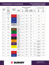
y LED indicators (panels with LED display; Figure 1)
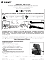
y Advanced LCD display (panels with meter module; Figure 2)
y Alarm Contacts: Form C dry contacts
y Side-accessible modular jack connections for alarm outputs
y Polarized, positive latching connectorized outputs
y Optional lacing bar kit (750-283-10) or telescoping rear rack support kit (750-277-10)
Figure 1. LED Display
Figure 2. Meter Module

TPA 250 FUSE PANEL
SETUP AND OPERATION MANUAL
PAGE 2 - PURPOSE AND APPLIcAbILITy
THIS PAGE INTENTIONALLY LEFT BLANK

TPA 250 FUSE PANEL
SETUP AND OPERATION MANUAL
UNPAckING AND INSPEcTION - PAGE 3
Section 3: Unpacking and Inspection
The Comm/net Systems TPA 250 Series fuse panel was carefully packaged at the
factory to withstand the normal rigors of shipping. However, you should carefully
inspect the box and contents to confirm that no damage has occurred in transit. Most
shipping carriers require notification of shipping damage within twenty-four hours of
delivery, and it is the responsibility of the recipient to inspect the shipment immediately
upon receipt.
3.1 Package Contents
Included with your product are the following items:
y TPA 250 Series fuse panel
y Rear lacing bar assembly
y Clear plastic input safety covers
y Mounting hardware kit with necessary screws and washers
y Optional lacing bar kit or rear rack support kit (if ordered)
Section 4: Installation
4.1 Installation Preparation
When selecting an installation location, ensure that all of the following conditions are
met before proceeding.
4.1.1 Elevated Operating Ambient Temperature
If you install the panel in a closed or multi-unit rack assembly, the operating ambient
temperature of the rack environment may be greater than room ambient. Therefore,
take care to install the equipment in an environment compatible with the maximum
ambient temperature (TMA) specified in Section 5.
4.1.2 Reduced Air Flow
Installation of the equipment in a rack should be such that the amount of air flow
required for safe operation of the equipment is not compromised.
4.1.3 Mechanical Loading
Mounting of the equipment in the rack should be such that a hazardous condition is
not achieved due to uneven mechanical loading.
4.1.4 Circuit Overloading
Give consideration to the connection of the equipment to the supply circuit and
the effect that overloading of the circuits might have on overcurrent protection and
supply wiring. Use appropriate consideration for equipment nameplate ratings when
addressing this concern.
4.1.5 Reliable Earthing
Maintain reliable earthing of rack-mounted equipment. Pay particular attention to
supply connections other than direct connections to the branch circuit (e.g., use of power
strips).
4.1.6 Disconnect Device
A readily accessible disconnect device must be incorporated in the building
installation wiring.

TPA 250 FUSE PANEL
SETUP AND OPERATION MANUAL
PAGE 4 - INSTALLATION
4.2 Mounting
NOTICE
y THIS PRODUCT MUST BE INSTALLED WITHIN A RESTRICTED
ACCESS LOCATION WHERE ACCESS IS THROUGH THE USE
OF A TOOL, LOCK AND KEY, OR OTHER MEANS OF SECURITY,
AND IS CONTROLLED BY THE AUTHORITY RESPONSIBLE
FOR THE LOCATION. THIS PRODUCT MUST BE INSTALLED
AND MAINTAINED ONLY BY QUALIFIED TECHNICIANS.
y SUITABLE FOR MOUNTING ON CONCRETE OR
OTHER NONCOMBUSTIBLE SURFACE ONLY.
Step 1. Select either position 1, 2, or 3 to install the mounting ears (see Figure 3).
Step 2. Attach the mounting ears with included 10-32 hardware (see Figure 4).
Step 3. Select the equipment rack location for installation of the fuse panel then
secure the panel to the equipment rack by tightening hardware into the
mounting ears (see Figure 5).
4.2.1 Optional Cable Lacing Bar Kit (750-283-10)
Step 1. Attach the rear cable lacing bar assembly by tightening the (4) 10-32 socket
head screws into the threaded holes located on each side of the chassis
towards the rear (see Figure 5).
4.2.2 Optional Rear Rack Support Kit (750-277-10)
An optional telescoping rear rack support kit (750-277-10) is available to help secure
the panel to the rear of the equipment rack and to distribute panel weight evenly. In
addition to the standard lacing bar included with the TPA 250 fuse panel, a new lacing
bar is included with this kit which can be repositioned on any of the available lacing bar
holes depending on the depth of the equipment rack. Use a hex key to relocate the new
lacing bar if needed. See Pages 15 & 16 for mechanical dimensions of rear rack support
kit.
Step 1. Slide the rails of the rear rack support assembly into the lacing bar assembly
from section 4.2.1 (see Figure 6).
Step 2. Secure the mounting ears to equipment rack via the slotted holes or PEM nuts.
Figure 6. Rear Rack Support Kit (750-277-10)
Figure 4. Mounting Ears (Postion 1 Shown)
Figure 3. Mounting Ear Positions
Figure 5. Cable Lacing Bar Kit (750-283-10)

TPA 250 FUSE PANEL
SETUP AND OPERATION MANUAL
INSTALLATION - PAGE 5
4.3 Chassis Ground
CAUTION
DO NOT ENERGIZE THE PANEL BEFORE
CHASSIS GROUND IS CONNECTED.
WARNING
DO NOT USE HARDWARE WITH A LENGTH EXCEEDING
3/4 INCH FOR CHASSIS GROUND CONNECTIONS.
The chassis ground is located on both sides of the panel. Two-hole lug landing
positions are provided. See table below for termination information. A minimum of #4
AWG chassis ground cable is required.
TABLE 2. CHASSIS GROUND TERMINATION SPECIFICATIONS
TERMINATION
TYPE
HOLE/STUD
SIZE CENTER TO CENTER
RECOMMENDED TORQUE
VALUE
Threaded Insert 1/4 in. 5/8 in. 75 in∙lbs
Step 1. Secure the ground cable to the chassis by tightening 1/4 in. hardware (see
Figure 7).
4.4 Input Connections
WARNING
y INPUTS MUST BE PROTECTED BY A LISTED CIRCUIT BREAKER
OR BRANCH RATED FUSE. THE CIRCUIT BREAKER OR FUSE
MUST BE RATED AT 125% OF THE PANEL RATING.
NOTICE
y MAKE SURE THAT ALL FEEDER CABLES HAVE HEAT SHRINK APPLIED
PRIOR TO TERMINATION, AND THAT NOOXIDE COMPOUND
IS APPLIED TO ALL COPPERTOCOPPER CONNECTIONS.
y SEE APPENDIX B ON PAGE 17 FOR COMPRESSION LUG
SPECIFICATIONS, TOOLING, AND ORDERING INFORMATION.
TABLE 3. INPUT TERMINATION SPECIFICATIONS
TERMINATION
TYPE
HOLE/STUD
SIZE CENTER TO CENTER
RECOMMENDED TORQUE
VALUE
Threaded Stud 1/4 in. 5/8 in. 75 in∙lbs
Step 1. Secure the RTN input cables/lugs to the RTN input studs located on the rear of
the panel (see Figure 8). Ensure that all hardware is tightened.
Step 2. Secure the HOT input cables/lugs to the HOT input studs located on the rear of
the panel (see Figure 9). Ensure that all hardware is tightened.
4.5 Safety Covers
Figure 7. Chassis Ground Landing
Figure 8. RTN Input Landing
Figure 9. HOT Input Landing

TPA 250 FUSE PANEL
SETUP AND OPERATION MANUAL
PAGE 6 - INSTALLATION
WARNING
FAILURE TO REINSTALL THE INPUT SAFETY COVERS
WILL CREATE AN ELECTRICAL HAZARD.
Included with each TPA 250 series fuse panel are (4) input safety covers which are
designed to help isolate the input terminations.
Step 1. Align the notch found on the included plastic safety covers with the slots
located at the rear of the panel.
Step 2. Firmly insert into place until fully seated (see Figure 10).
4.6 Output Connections
CAUTION
y DO NOT PERFORM THIS STEP ON
CIRCUITS WITH FUSES INSTALLED.
y ENSURE NO POWER IS PRESENT ON THE CIRCUIT
BEING WIRED BEFORE PROCEEDING.
NOTICE
SEE APPENDIX C ON PAGE 18 FOR TERMINAL SPECIFICATION
AND CABLE WHIP ORDERING INFORMATION.
There are (12) positive latching DC connector positions for the output circuits found
on the TPA 250 fuse panel, available in either 40A or 100A connector configurations.
Cable whips are available in a variety of lengths and wire gauges. Contact Comm/net
sales for cable whip ordering information. Refer to the front of the panel for the circuit
mapping card for circuit mapping information.
Step 1. Insert the DC plugs into the output receptacles until they click. The connectors
are keyed to ensure correct polarity (see Figure 11).
Figure 10. Safety Covers
Figure 11. Output Connections (40A Version Shown)

TPA 250 FUSE PANEL
SETUP AND OPERATION MANUAL
INSTALLATION - PAGE 7
4.7 Fuse Installation
NOTICE
y USE BUSSMANN TPA TYPE FUSES ONLY.
y FUSES MUST CARRY A 10kA OR HIGHER INTERRUPT RATING.
Step 1. Ensure that connected loads are in the off position, then firmly insert a TPA
fuse of sufficient ampacity into the position to be fed (see Figure 12).
Step 2. Turn on the connected load.
4.8 Alarm Installation
NOTICE
WHEN DAISY CHAINING, THE ALARM MUST
BE MONITORED NORMALLY OPEN.
The TPA 250 series fuse panel has Form-C dry alarm contacts for remote alarm
monitoring. If alarm monitoring is required, (2) 8p8c (RJ-45) modular jacks are provided
for alarm connections. The (2) jacks support easy daisy chaining of panels.
The 8p8c modular jacks are located on the left side of the panel. Refer to mechanical
drawings found in Appendix A for more details.
Step 1. Plug in a UTP cable with a TIA/EIA T568B termination into the alarm jack (see
Figure 13). Refer to Table 4 for termination pinout information.
Step 2. Connect the cable to the site alarm monitoring system.
Step 3. If daisy chaining is required, connect a UTP cable with TIA/EIA T568B
termination into the second jack and connect the other end to the next panel
in the chain. Repeat this process until all panels are connected.
TABLE 4. ALARM CONTACT PINOUT
PIN 1 PIN 2 PIN 3 PIN 4 PIN 5 PIN 6 PIN 7 PIN 8
Major COM Major NC Major NO Reserved Reserved Reserved Reserved Reserved
4.9 Installation Checklist
y Rack mount ears (19 or 23 in.)
y Ears mounted to panel and rack securely
y Chassis ground cable/lug securely tightened
y Input power cables/lugs and return cables/lugs securely bolted/connected to rear
of panel
y Heat shrink installed on cables
y Fuse fail alarm contacts wired to remote monitoring device (if required)
y Output connections secured
y Fuses sized as required for each load
y All safety covers attached
Figure 12. TPA Fuse Installation
Figure 13. Alarm Jacks

TPA 250 FUSE PANEL
SETUP AND OPERATION MANUAL
PAGE 8 - INSTALLATION
THIS PAGE INTENTIONALLY LEFT BLANK

TPA 250 FUSE PANEL
SETUP AND OPERATION MANUAL
OPERATION - PAGE 9
Section 5: Operation
5.1 LED Display
Modules with the LED display include three indicators: A Power, B Power, Alarm.
5.1.1 A Power LED
The A Power LED will light up when power is present on the A input bus.
5.1.2 B Power LED
The B Power LED will light up when power is present on the B input bus.
5.1.3 Alarm LED
The Alarm LED will light up if a fuse is blown.

TPA 250 FUSE PANEL
SETUP AND OPERATION MANUAL
PAGE 10 - OPERATION
THIS PAGE INTENTIONALLY LEFT BLANK

TPA 250 FUSE PANEL
SETUP AND OPERATION MANUAL
PRODUcT SPEcIFIcATIONS - PAGE 11
Section 6: Product Specications
6.1 Electrical Specications
NOTICE
USE BUSSMANN TPA TYPE FUSES ONLY.
FUSES MUST CARRY A 10kA INTERRUPT RATING.
TABLE 5. TPA 250 SERIES FUSE PANEL SPECIFICATIONS
MODELS:
016-2121-10
016-2123-10
016-2125-10
016-2127-10
MODELS:
016-2122-10
016-2124-10
016-2126-10
016-2128-10
Type of Input Single Input Dual Input (A/B)
Circuits 12 12 (6A/6B)
Input Voltage (+/- 0%) -42 to -60V DC -42 to -60V DC
Input Current 250A Max 250A Max
Short Circuit Withstand 10kA 10kA
Maximum Fuse Size 50A TPA 50A TPA
Maximum Per Circuit Current 40A 40A
Max Operating Altitude 2000 m 2000 m
Max Ambient Temperature 50º C 50º C
Width 17 in. 17 in.
Height 1.75 in. 1.75 in.
Depth (Not Including Lacing Bar Kits) 18 in. 18 in.
Weight 8.5 lbs. 8.5 lbs.
UL File Number E473904 E473904
UL Standard ANSI/UL 60950-1 ANSI/UL 60950-1

TPA 250 FUSE PANEL
SETUP AND OPERATION MANUAL
PAGE 12 - PRODUcT SPEcIFIcATIONS
TPA 250 FUSE PANEL
SETUP AND OPERATION MANUAL
PAGE 12
Appendix A: Mechanical Drawings
FRONT VIEW
1.720
LED MODULE
METER MODULE
1.000
RETURN
HOT HOT
RETURN
A INPUT
B INPUT
100A CONNECTORIZED OUTPUTS
40A CONNECTORIZED OUTPUTS
REAR VIEW

TPA 250 FUSE PANEL
SETUP AND OPERATION MANUAL
PRODUcT SPEcIFIcATIONS - PAGE 13
TPA 250 FUSE PANEL
SETUP AND OPERATION MANUAL
PAGE 13
SIDE VIEW

TPA 250 FUSE PANEL
SETUP AND OPERATION MANUAL
PAGE 14 - PRODUcT SPEcIFIcATIONS
TPA 250 FUSE PANEL
SETUP AND OPERATION MANUAL
PAGE 14
TOP VIEW
17.000
18.000
16.000
/