Page is loading ...

Page 1
CGC-1e Complete Greenhouse Controller
OVERVIEW
The CGC-1e Complete Greenhouse Controller from C.A.P. controls all of the main
devices required in today’s modern hydroponic garden.
IMPORTANT STUFF TO REMEMBER
The CGC-1e is designed to operate from a 120vac, 15-amp power source. It can safely control up to 15-amps of equipment
including up to 1000 watts of HID lights. If required, additional lights and larger equipment can be connected to the CGC-1e
by using our HPR, MLCs or UPM “Universal Remote Power Modules”. In addition to lights, the CGC-1e also maintains the
temperature and humidity by controlling your exhaust fan(s). CO
2
levels can be controlled with the built-in timers, which are
coordinated with your exhaust fans and function only when the lights are ON. Or you can upgrade later to PPM Part-Per-
Million control by adding the PPM-1c CO
2
monitor. And to complete the package, the built in Adjustable Recycling Timer is
perfect for controlling your hydroponic pumps and more!
PROTECTION & SAFETY
The CGC-1e is overload protected a main 15-amp fuse. Do not exceed the maximum rating of the CGC-1e.
IMPORTANT: Replace blown fuses with fuses of the same rating ONLY!
Note: A surge suppressor power strip is always
recommended when operating electrical equipment such as the CGC-1e.
WARRANTY
The CGC-1e is protected by our 3-year limited warranty. All components are warranted by R & M Supply against defects in
workmanship and materials under normal use for 3-years from the date of purchase. The CGC-1e is 100% maintenance-free
and does not require service.
INSTALLATION / START-UP
There are a few requirements for a successful installation and start-up.
1) The CGC-1e must be mounted in a vertical position.
Mounting feet are included to allow you to secure the unit to a wall.
2) The CGC-1e requires “free air movement” to maintain temperature and humidity accuracy.
The top and bottom of the
enclosure has ventilation slots to provide air flow through the unit however, we greatly recommended using an oscillating
fan in the growing area to provide fresh air for the internal humidity sensor and provide adequate ventilation for the
internal electrical components.
3) A dedicated 120 VAC, 15-amp power supply is recommended.
A ground wire (3-wire outlet) must be used.
Do not use 2-wire adapters or cords to operate the CGC-1e.
4) The CGC-1e must be protected from water. Do not
mount the unit where it can be exposed directly to water.
5) Read the rest of the manual!!! It has been designed to take you through step-by-step to make start-up a breeze.
WORD TO THE WISE...
CGC-1e
Before attempting to operate the CGC-1e, you should at least take the time
to look at the Example Connection diagram on page 2 and read the “Start-
up Procedure on page 3 of this manual. To get the most out of the CGC-1e,
familiarize yourself with this manual. It contains many useful hints;
examples and a troubleshooting guide.

Page 2
“FRONT PANEL”
OVERVIEW
“The CGC-1e is a self-contained greenhouse control system designed for people who want a reasonable, simple to
operate, complete greenhouse controller.
EXAMPLE CONNECTION DIAGRAM
DO NOT EXCEED 15 AMPS TOTAL
Night device
outlet
Hydro “ON”
timer
CO
2
device
outlet
24-hour
timeclock
(2) Exhaust
outlets
Humidity
controller
CO
2
“ON”
timer
Optional PPM–1c
quick connect
Hydro “OFF”
timer
(2) Light
outlets
CO
2
“OFF”
timer
Hydro mode
selector switch
Temperature
controller
(2) Hydro pump
outlets
Fuse protected 15-amps
@
120
volts
Control up to (2)
Exhaust Fan(s) or
A/C units
1
000
600
Control (2) pumps.
Selectable 24-hour
operation or daytime only.
15-amp fuse
protected
CGC-1e
Exhaust Lights
Night
Hydro
CO
2
PPM
O
p
tion
24-hour
Timeclock
PPM-1c
1250
CO
2
Valve
or Generator
Fan, heater, or
dehumidifier
600
Optional CO
2
PPM sensor
Control multiple HID lights
with a MLC or UPM

Page 3
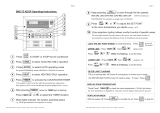
START-UP PROCEDURE
OVERVIEW
“There is no substitute for reading and understanding the operating manual however... You can use the
instructions on this page for a trouble -free start-up”.
HOW TO START-UP THE CGC-1e
1) Locate a suitable source for power. A “3-wire”, grounded, 15-amp dedicated circuit is recommended.
2) Secure the enclosure to a wall using the enclosed mounting “feet”. The CGC-1e requires a vertical orientation for proper
internal ventilation. If proper ventilation is not provided, the thermostat may not be able to properly control the
temperature & humidity of the growing area.
3) Plug the CGC-1e into the power source. Do not connect your lights until you have set the “ON and “OFF” times on the
24-hour timeclock.
4) If you are using a PPM-1c CO
2
sensor, connect it by removing the “jumper-plug” provided with the CGC-1e and
connecting the PPM-1c quick-disconnect. Plug the PPM-1c into a source of constant 120-volt power. Refer to the PPM-1c
instructions for information on how to operate the PPM-1c properly.
* Note: The pre-wired “jumper plug” must be connected if the PPM-1c is not being used!
5) You can now set the thermostat and de-humistat to the approximate settings you would like to use. A small, inexpensive
combination thermometer and hygrometer works just fine to “dial in” the exact settings. Just compare the reading on the
thermometer to what the CGC-1e is set at and adjust as required.
6) You can now select the Hydro mode you would like to use. Choose between operating the Hydro outlet during the
“Daytime” only or, 24-hours a day. Move the Hydro mode switch to the appropriate position. Moving the switch to the
center “OFF” position momentarily will reset the timer.
7) There are 4 timers on the CGC-1e, which are used to control a hydroponics pump and a CO
2
valve or generator. To fully
understand the timers that control the CGC-1e, refer to the Timers section of this manual. Set the Hydro and CO
2
timers to
your desired settings before continuing. (Refer to Timers)
8) The 24-hour timeclock can now be set. Push in the trip levers on the front face of the timer dial for the time you want your
lights to be “ON”. Rotate the dial to the current time to set the timer.
9) You can now plug the equipment you will be using into the appropriate receptacles. Remember that the CGC-1e can
handle a combined load up to 15-amps. A single 1000-watt HID ballast needs over 9-amps alone. Select and size your
pumps and fans appropriately or use our UPM-1 or MLCs to increase power capacity.
*Note: We highly suggest NOT plugging in your HID ballast just yet.
10) When the “day” cycle begins, the “Lights” indicator will light up to confirm power is going to the (2) light receptacles. If
you have selected the “Daytime” setting on the Hydro mode, the “Hydro Pumps” indicator will also light up to indicate
your pump is powered for the amount of time you selected
11) You can manually override the timeclock to switch from “night” to “day” or back to Night by rotating the outer dial of the
timeclock slowly clockwise. At night, the Lights and CO
2
are disabled while the thermostat and humistat continue to
control the temperature and humidity.
* NOTE: The Hydro outlet will also be disabled if the “Daytime” mode is selected on the Hydro mode switch.
12) When all settings have been confirmed, the HID lights or UPMs can be plugged into the “Lights” receptacles. If more than
1000 watts are to be controlled, use our Universal Power Modules or the MLCs.
* IMPORTANT: Do not plug in more than 1000 watts worth of lighting into the CGC-1e receptacles.
13) Monitor the equipment connected to the CGC-1e to ensure proper operation. Small adjustments are likely to be made until
you find the right combination of controls. Once you are happy with the settings sit back and enjoy the show!
For more details concerning any of the CGC-1e functions, refer to the appropriate section of this manual.

Page 4
“CONTROLS”
OVERVIEW
“The CGC-1e controls your light cycles, temperature, humidity and CO2 levels… automatically! No more
guesswork! The CGC-1e lets you work smarter not harder.
24 HOUR, TIMECLOCK
The timeclock selected to run the CGC-1e performs all of the day to night transitions required for crops requiring controlled
photoperiods. It can directly control up to 1000 watts of HID lights.
To set the current time on the timeclock, turn the dial clockwise until the current time on the outer dial lines up with the arrow
on the inner dial. To set the timeclock on and off times, carefully push in each of the white trip levers at the times you want the
lights to be on.
*NOTE: If power is interrupted, the timeclock will have to be reset.
TEMPERATURE CONTROLLER
The CGC-1e utilizes a remote-bulb thermostat with a 36” lead to control ventilation and cooling functions. This allows you
to place the temperature sensor up to 36” away from the CGC-1e. The thermostat can be set to control temperature from
50 – 115’F.
The thermostat is coordinated with the CO
2
control system and the exhaust receptacles to maintain a constant temperature.
When the temperature rises above the set point selected on the thermostat, the CO
2
system is disabled and the Exhaust
receptacles are enabled. When the temperature level drops below the set point, the CO
2
system is re-activated.
IMPORTANT:
To achieve the greatest accuracy, provide the CGC-1e with plenty of “fresh air”. The enclosure is designed to
allow air to pass over the humidity sensor.
HUMIDITY CONTROLLER
The CGC-1e utilizes a de-humistat to control ventilation and humidity levels. The de-humistat can control humidity levels
from 20% - 80%.
The de-humistat is coordinated with the CO
2
control system and the exhaust receptacles to maintain a constant humidity.
When the humidity rises above the set point selected on the de-humistat, the CO
2
system is disabled and the Exhaust
receptacles are enabled. When the humidity level drops below the set point, the CO
2
system is re-activated.
HYDRO MODE SELECT SWITCH
The Hydro mode select switch is used to select whether the hydro outlet will cycle 24-hours or only during the day. The mode
selector switch also doubles as a Hydro bypass switch. Each time the switch position is changed to the center “OFF” position,
the hydro timers will reset and initiate a new cycle. This comes in handy during set-up of the hydro pumps and timer settings.
NOTE: *Leaving the mode select switch in the center position disables the hydro function.
NIGHT ONLY DEVICE
An additional outlet is provided which is powered only at “night” when the lights are turned OFF. This works great for
heaters, fans and dehumidifiers, which need to run only at night.
PPM CO2 OPTION
The CGC-1e has a standard timed CO
2
control sequence, which can be improved upon greatly by simply connecting the
optional PPM-1c. Simple operation, user selectable set point and on-board calibration makes the PPM-1c the perfect
companion to the CGC-1e.

Page 5
TIMERS
OVERVIEW
The CGC-1e uses 2 digital timers to control the hydroponics and CO
2
functions. One of the timers control the
hydroponics pump frequency and duration, and the other one determines CO
2
injection / generation time and
frequency / sample time.
ADJUSTABLE RECYCLING TIMERS
Adjustable recycling timers provide an adjustable “ON” / “OFF” cycle for various devices. The 4-adjustable recycling timers
onboard the CGC-1e are set using the dial on the front face of the enclosure. The timer name and range of each timer is printed
around the timer dials. Because the dials of the CGC-1e are small to conserve space, the settings may have to be adjusted to an
actual time setting. If necessary, use a watch or stopwatch to confirm the settings are correct. Once the timers are set, they are
repeatable to +/- .2%.
IMPORTANT: In order for the timers to accept a new setting, the timer must either complete 25% of it’s present cycle or,
power must be cycled off, then on.
RESETTING HYDRO TIMERS:
The Hydro timers can be reset by switching the Hydro mode select switch to the center
“OFF” position momentarily.
RESETTING CO2 TIMERS:
To reset the CO
2
timers and restart the CO
2
cycle, turn the temperature or humidity controller
down momentarily. This will trigger the “end of cycle” sequence and start the Exhaust duration timer.
RESETTING ALL TIMERS:
If you choose to cycle power to accept new timer settings, we recommend disconnecting the
lights prior to setting these timers. Disconnecting the lights will eliminate the chances of damaging the lights by cycling power
“ON” and “OFF” to the lights. Follow the procedures below to set the Hydro and CO
2
timers correctly.
HYDROPONICS TIMERS
The Hydroponic outlet can be configured to cycle one of two ways… 24-hours a day or, during the “daytime” only. Simply
moving the Hydro Mode selector switch to either the “24-Hour” or the “Daytime” position enables the desired mode. When
used in the Daytime” mode, the Hydro outlet will only cycle while the lights are on. The “24-hour” mode works great for NFT
or aeroponic systems that require moisture during the day and night. The mode selector switch also doubles as a Hydro bypass
switch. Each time the switch position is changed, the hydro timers will reset and initiate a new cycle. This comes in handy
during set-up of the hydro pumps and timer settings.
There are two timers that control the hydroponics receptacle, Hydro “ON” and Hydro “OFF”. The CGC-1e’s Hydro “ON”
time can be set from 1 second to 40 minutes; the Hydro “OFF” time can be set from 1 minute to 8 hours. Set the timers by
moving the dial to the appropriate position.
CO2 TIMERS
The CGC-1e controller also provides an integrated timed CO
2
control system. As with all of CAP’s greenhouse and CO
2
controllers, a thermostat and a de-humistat are used to interrupt CO2 use if the temperature or humidity rises above the preset
level. The CO
2
is also disabled at “night” by the 24-hour timeclock.
During the “day”, the CGC-1e controls your CO
2
valve or generator by turning the CO
2
outlet on for a certain amount of time
and then off for a pre-determined amount of time, repeatable +/- 2%.
The CO
2
Inject timer or “ON” time can be set from 1 second to 40 minutes. The CO
2
inject frequency timer or “OFF” time can
be set from 1 minute to 8 hours. This provides a great deal of flexibility and control options.
For more detailed information about the CO
2
timers and sequence, refer to the CO
2
Control section of this manual.

Page 6
CO2 CONTROL
OVERVIEW
“Pound for pound, dollar for dollar, the CGC-1e offers one of the most advanced environmental / light / hydro and
CO
2
control system on the market”.
“SUPPLEMENTAL CO
2
”
Let's talk about ... Carbon Dioxide. CO
2
is present in relatively low quantities, (300-600 PPM) in your normal, generic, run of
the mill everyday air. But plant growth can be increased and accelerated if the level of CO
2
is increased to, let’s say... 1000 -
1500 PPM. For this reason, the CGC-1e can control CO
2
distribution for those people who prefer to use supplemental CO
2
.
There are some inherent dangers associated with using CO
2
. Here are some of the rules to remember when using CO
2
:
A) Cylinders (bottles) of compressed CO
2
should never be stored inside the growing area or anywhere else where the
temperature may rise above 100’f.
B) The growing area should not be occupied while CO
2
is in operation. (Get out!)
C) Do not enter the growing area until the CO
2
has been exhausted. (Stay out!)
D) CO2 is heavier than air and will accumulate towards the ground. (Don’t lie down on the job!)
E) In high enough concentrations CO
2
can kill!!! The OSHA maximum “Personal Exposure Level” is 5000 PPM.
*Note: The CGC-1e CO
2
control system can be used for both compressed CO
2
cylinders, and generators. The CO
2
receptacle is
120vac. Compressed CO
2
cylinders require an approved regulator / flow gage and a valve.
If optimum CO
2
“mileage” is desired, a self contained air conditioner or other “Closed loop” cooling method is highly
recommended. A closed loop system will regulate temperatures within the zone allowing you to extend the CO
2
maximum
cycle time thus reducing CO
2
use dramatically.
Another method of reducing heat build up includes utilizing “Ventilated light hoods”. Just be sure to make the ventilation
system of the hood as airtight as possible so that your precious CO
2
is not being drawn out of the area by the ventilated hood
exhaust fan.
If sufficient CO
2
is provided and the proper level of nutrients and light is available, a 35% increase in growth rate is possible.
However if you suspect the higher temperatures are adversely affecting the plants, a shorter CO
2
cycle may produce better
results. Remember that a shorter CO
2
cycle duration translates to increased CO
2
usage. Each application is different, so there is
some work involved in finding the optimum set-up.
CO2 CONTROL MODES
The CGC-1e provides both a standard timed CO
2
mode and an optional integrated CO
2
PPM control mode. Of course, the time
clock will ensure CO
2
is only used during the “day”. The optional PPM-1c sensor is one of the most precise and efficient
method of distributing CO
2
. The PPM-1c control will be described later, but first, let me explain how to operate the standard
timed CO
2
system.
*Note: The pre-wired “jumper-plug” is used to bypass the PPM controller functions when the PPM-1c is not used.
Make sure it is properly connected when running the timed CO
2
sequence.
TIMED CO
2
CONTROL MODE
1) The CO
2
Inject Duration timer can be set from 1 second to 40 minutes. When the CGC-1e’s standard 24-hour timeclock
switches to “daytime”, the CO
2
cycle begins. The CO
2
outlet is energized for a predetermined amount of time using the
CO
2
Inject Duration timer.
2) The CO
2
Frequency timer works in conjunction with the CO
2
Injection timer. This timer can be set from 1 minute -
8 hours. During the CO
2
cycle, the CO
2
outlet will be turned off for the amount of time set on this timer. The CO
2
Inject
Duration timer and the Frequency timer continue to recycle until the thermostat or humistat turns on the fans. When the
exhaust is turned back off, the CO
2
cycle is re-started.
Note: These two timers continue to function in harmony with the optional PPM-1c sensor. The PPM-1c simply tells the
CGC-1e whether the CO
2
level being measured is above or below the adjustable set point on the PPM-1c. The timers still
control the CO
2
“ON” and “OFF” time.

Page 7
PPM (Part-Per-Million) CO
2
CONTROL MODE
As mentioned previously, the CGC-1e can control CO
2
levels within the growing area with “Part-Per-Million” accuracy when
used in conjunction with the PPM-1c controller. Simply removing the jumper plug and connecting the PPM-1c into the
standard quick-disconnect on the bottom of the CGC-1e instantly gives you the ability to fully control all atmospheric
conditions which affect timed CO
2
systems.
*Note: The CO
2
Frequency timer acts as a CO
2
sample timer when using the PPM-1c controller. Because it may take a couple
of minutes from the time CO
2
is released for the PPM-1c to detect a higher CO
2
level, this timer will provide a delay for the
PPM controller to sense this increase in the CO
2
level before releasing more CO
2
. If you find the CO
2
level is “overshooting”
the CO
2
set-point, try increasing the CO
2
sample timer or decrease the CO
2
Inject timer. This will give the PPM-1c more time
to sense the rise in CO
2
resulting in reduced “overshoot”.
THE PPM-1c
The PPM-1c controller consists of an infrared detector capable of measuring atmospheric CO
2
levels from 0 to 5000 PPM. The
PPM-1c is powered by an 18 vdc to 24vac power supply. When it is connected, it will enter a “warm-up” mode. Once the
PPM-1c has completed the “warm-up”, it will begin to self calibrate. This may take an additional minute. During this time, the
digital readout may be fluctuating, this is normal. When the digital readout stabilizes, a level between 350 to 650 should be
displayed. Be careful however, simply breathing on the PPM-1c controller will greatly increase the CO
2
level in the air
resulting in a higher reading.
IMPORTANT!!! Do not start a CO
2
cycle until the PPM-1c has completed the “warm-up” and the display has stabilized.
Once the PPM-1c has been connected, it remains powered as long as it is plugged in. The controller will continuously display
the exact CO
2
PPM level in part per million.
The PPM-1c is a portable device and comes with a 5-foot cable so that spot checks can be made.
A simple procedure allows the user to check and reset calibration… otherwise; the PPM-1c requires no adjustment or service.
Warning: Be careful not to expose the PPM-1c to water, as it is not water-resistant!

Page 8
OPTIONS
OVERVIEW
The CGC-1e can be upgraded and expanded by using our expansion devices including the UPM-1, MLC-4 or the precision
PPM-1c. The Universal Power Modules and Master Light Controllers allow you to run multiple pumps, fans and lights by
controlling remote relays. The PPM-1c allows you to control CO
2
with Part-Per-Million accuracy!
UNIVERSAL POWER MODULE (UPM-1)
The UPM-1 Universal Power Module is a unique device that can allow the user to run
additional HID lights or control multiple fans / air conditioners etc.
The UPM-1’s “plug-box” was designed to be plugged into a standard household outlet.
The 16-foot long “trigger cable” coming from the UPM-1 is then connected to your
control device such as a time clock or thermostat. When the control device turns ON, the
relay inside the UPM-1 box applies power to the twin outlets on the front of the UPM-1
turning ON whatever is plugged into it. This allows you to run additional lights etc.
from a different circuit with one common control device.
The UPM-1 is rated at 15-amps @ 120 volts.
PART-PER-MILLION CO
2
SENSOR (PPM-1c)
To take full advantage of supplemental CO
2
, you must be able to precisely control the
level of CO2. This is made possible by plugging in our “CO
2
Controller”, the PPM-1c.
The PPM-1c controller is constantly sampling the level of CO
2
in the growing area and
can measure from 0 to 5000 PPM. The PPM-1c displays the current CO
2
level in PPM
using large a 4-digit LED display. It then transmits that information to the CGC-1e.
The PPM-1c is powered by a 18-24volt power supply.
MASTER LIGHTING CONTROLLER (MLCs)
The MLC-4 and MLC-4a Master Lighting Controllers are the best devices for
controlling up to (4) HID lights from one time clock or controller. Like the HPR-1,
power must be brought into the “input” side of the control relay. The MLC-4 features (4)
standard 240v outlets, which your ballasts are plugged into. The MLC-4a is designed for
120 volt ballasts however it can also be used to run ballasts wired for 240-volt operation,
which have 120-volt power cords. The MLC-8 Master Lighting Controller is the best
device for controlling up to (8) HID lights from one time clock or controller. Power is
brought into the MLC-8 by hardwiring up to a 40-amp circuit. The MLC-8 features (8)
standard 240v outlets, which your ballasts are plugged into.
The MLCs both feature a 120-volt trigger cable to plug into a standard 24-hour timer or
controller. The MLC-4 & MLC-4a are rated 30-amps @120/240 volt. The MLC-8 is
rated at 40-amps @ 240 volt.
HID LIGHTING CONTROLLER (HLC-2e)
The HLC-2e HID lighting controller was primarily designed to protect your expensive
HID lights from HOT-STARTS.
A “Hot-Start” occurs whenever your lights are turned off… and then back on before
the
lamps are allowed to cool off. Hot-starts caused by power outages reduces your lamp’s
life and intensity. It can be plugged into either of the “Lights” outlets.
When the HLC-2e is connected to your lights, it will sense a power interruption, and
start a 15-minute time-delay to keep the lights from trying to re-fire while the cool down.
The HLC-2e can also be used to delay other devices from starting.
The HLC-1e is rated for 15-amps @ 120volts.

Page 9
TROUBLESHOOTING
If you are having problems with this unit, refer to these troubleshooting hints. Also, refer to the connection diagram
to ensure your devices are connected properly.
Problem Suggested Action
I have no lights and no
function at all.
Check the fuse and main power. Replace the fuse if required with the correct rated fuse.
Check the equipment connected to the CGC-1e for problems and/or short circuits.
The fuse continues to
blow.
If the fuse blows repeatedly, verify the devices connected to the unit are working properly and that they
are not too large for the CGC-1e to safely control.
You may need to consider using expansion modules, (UPM / HPR / MLC) to decrease the amperage
(load) on the CGC-1e fuse.
My CO2 outlet never
comes on.
Verify the PPM-1c jumper or the PPM-1c is connected.
If the Exhaust outlet is ON, the CO
2
will not be allowed to run. Turn up the Temperature and Humidity to
a higher setting.
In order for the CO
2
outlet to function, the timeclock must be in “Daytime” mode. The CO
2
is only
activated when the lights are “ON”.
The fans are running
so often, the CO2 is
hardly ever ON.
You may have too much heat building up in your area or too small of an exhaust fan. Reduce the heat
sources or increase your fan size.
You may also consider using a “closed-loop” air conditioner to keep the temperature and humidity below
the set points so that CO
2
is allowed to run for longer amounts of time.
My CO2 consumption
seems to be quite high.
Make sure your area is sealed. You may want to install a motorized damper to seal your exhaust fans
when they are “OFF”. Even though the CGC-1e operates a standard “timed-release” sequence, you may
still be “wasting” CO
2
.
If you are operating compressed CO
2
valves, consider purchasing the optional PPM-1c “Part-Per-Million”
sensor to upgrade to PPM control. The PPM-1c offers a significant improvement in CO
2
efficiency.
The CO2 level
“overshoots” the PPM-
1c set point
considerably.
Small areas need less “Inject Duration” time than do larger areas. Larger areas need more “Inject
Frequency” time in order to give the CO
2
time to “mix” properly with the ambient air and measured by the
PPM sensor.
Start with lower CO
2
timer settings for small areas and increase the timer settings for larger ones.
The Hydro pumps are
not cycling properly.
The Hydro pump outlets can be operated 24-hours a day or only when the “Lights” are “ON”. The “Hydro”
selector switch also has a center “OFF” position, which can be used to “reset” the timing function. Make
sure the switch is not turned “OFF”.
MAKING CONNECTIONS
All of the main functions controlled by the CGC-1e are accessed using (8) standard 120 VAC, 15-amp receptacles mounted on
the sides of the enclosure. This allows you to simply “plug in” any standard device without hardwiring or hassles. Printed
labels on the front face of the enclosure identify the receptacles.
We highly recommend using only 3-wire devices with a ground. Suitably double-insulated devices are acceptable. Keep in
mind that the combined amperage draw on all of the devices connected to the CGC-1e must be less than 15-amps @ 120 VAC.

Page 10
MAINTENANCE / SPECIFICATIONS
SPECIFICATIONS:
System operating voltage 120vac +/- 20% @ 50-60 Hertz
Maximum Switching amperage 15-amps @ 120vac
Overload protection 15-amp normal blow fuse
Operating temperature 0 - 50’ C / 32 - 122’ F
Maximum humidity 95% RH (Non-condensing)
Temperature control range 50-115’ F with a 7’ F differential, +/- 3.6’
Humidity control range 20 - 80% RH with a 5% differential
Adjustable timer repeatability +/- .2% under fixed conditions
Timer setting accuracy +/- 5%
Hydro “ON” timer 1 second to 40 minutes
Hydro “OFF” timer 1 minute to 8 hours
CO2 Inject duration timer 1 second to 40 minutes
CO2 Inject frequency timer 1 minute to 8 hours
24-hour timeclock accuracy +/- 3% monthly
Dimensions 10” X 8” X 7”
Weight Less than 6 lbs.
Relay operations Minimum 100,000 electrical / 10,000,000 mechanical
MAINTENANCE:
1) Consult the troubleshooting chart for a listing of the most common problems.
2) DO NOT open the enclosure!!! There are no components that require maintenance.
3) Do not use this equipment for purposes other than what it is designed for. It will provide many years of trouble-free
service when used properly.
4) In the event you cannot solve the problem, first consult the dealer who sold the unit then contact the factory for
instructions on how to return it to the factory for repair.
PUBLISHED BY R & M Supply INC.
COPYRIGHT 2008 BY R & M Supply
ALL RIGHTS RESERVED.
Liability statement:
R & M Supply and their retailers and distributors are not responsible for any damage or injuries (consequential or otherwise)
arising from the use of this device. The purchaser assumes all responsibility for the use and proper installation of this device.
/