Page is loading ...

WLA200 Rev140407
1
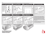
TANK INDICATOR
WLA200 WATER TANKS
WLA260 CLASS A FOAM CONCENTRATE TANKS
WLA270 CLASS B FOAM CONCENTRATE TANKS
Document Number:
XE-WLA2PM-R0A
PRIMARY and REMOTE
DISPLAYS
HORIZONTAL
OPTION
MAXVISION
LED TANK
DISPLAY
CAB
MINIATURES
FIRE RESEARCH CORPORATION
www.reresearch.com
26 Southern Blvd., Nesconset, NY 11767
TELE 631.724.8888 FAX 631.360.9727 TOLL FREE 1.800.645.0074

WLA200 Rev140407
2
CONTENTS
Table of Contents
CONTENTS ................................................................................................................ 2
List of Figures ........................................................................................................ 3
INTRODUCTION ...................................................................................................... 4
Overview ................................................................................................................ 4
Features .................................................................................................................. 4
Specications ......................................................................................................... 5
GENERAL DESCRIPTION ....................................................................................... 6
Components ........................................................................................................... 6
INSTALLATION ........................................................................................................ 8
Install Display Module........................................................................................... 8
Install Cab Miniature Display ................................................................................ 8
Install Pressure Sensor ......................................................................................... 10
Install Pressure/Vacuum Foam Tank Vent ........................................................... 12
Install MaxVision LED Tank Display .................................................................. 14
Program MaxVision LED Tank Display .............................................................. 14
Install Remote Light Driver ................................................................................. 16
Install Buzzer ....................................................................................................... 16
OPERATION ............................................................................................................ 17
Options ................................................................................................................. 17
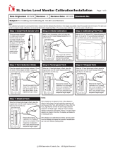
CALIBRATION ........................................................................................................ 18
Overview .............................................................................................................. 18
Non-Linear Calibration ........................................................................................ 19
Linear Calibration ................................................................................................ 20
Full Tank Correction ............................................................................................ 21
DIAGNOSTICS ........................................................................................................ 22
WIRING .................................................................................................................... 24
Primary Display ................................................................................................... 24
Remote, Cab Miniature, and LED Displays ........................................................ 25
Remote Light Driver ............................................................................................ 26
Typical System Conguration ............................................................................. 27
CLEAN/INSPECT PRESSURE/VACUUM FOAM TANK VENT ......................... 28
PARTS LIST ............................................................................................................. 29

WLA200 Rev140407
3
List of Figures
Figure 1. Display Module Mounting Dimensions ..................................................... 9
Figure 2. Cab Miniature Display Mounting Dimensions ........................................... 9
Figure 3. Pressure Sensor ......................................................................................... 11
Figure 4. Pressure/Vacuum Foam Tank Vent ........................................................... 13
Figure 5. MaxVision LED Display Mounting Dimensions ..................................... 15
Figure 6. Remote Light Driver ................................................................................. 16
Figure 7. Diagnostics - Faults .................................................................................. 22
Figure 7. Diagnostics - Warnings ............................................................................. 23
Figure 8. Primary Display Wiring ........................................................................... 24
Figure 9. Remote, Cab Miniature, and LED Display Wiring ................................. 25
Figure 10. Remote Light Driver Wiring .................................................................. 26
Figure 11. Typical System Conguration ................................................................ 27
Figure 12. Clean and Inspect Pressure/Vacuum Foam Tank Vent ........................... 28
Figure 13. Parts List ................................................................................................. 29

WLA200 Rev140407
4
INTRODUCTION
Overview
The FRC TankVision indicator shows the actual volume of liquid in a tank. The
liquid in the tank exerts a pressure that is measured by a sensor. As the amount of
liquid changes, the pressure it exerts on the sensor changes proportionally. The pressure
change is used to calculate the exact volume of liquid in the tank. The TankVision can
be calibration to accurately display the volume of liquid in tanks of all shapes and sizes.
The display module is able to communicate with other display modules over the
FRC datalink. This allows for one master display module to control multiple displays.
The module also provides an output for cab miniature displays, remote light drivers,
and a low level warning buzzer.
The TankVision indicator is a unique design made up of an extended wide view
lens with nine super bright LEDs mounted behind it. This allows the display to be
visible and clearly read from all line-of-sight angles for a full 180 degrees.
The pressure/vacuum foam tank vent is supplied for use on foam concentrate storage
tanks. These tanks should remain closed to the atmosphere. The FRC vent enables
the tank to compensate for changes in pressure or vacuum due to thermal expansion,
lling, or when withdrawing foam concentrate from the tank.
The MaxVision LED tank display provides a remote, wide angle view of how
much is in the tank in 1/8 tank level increments.
The remote light driver provides the option to have four 60 watt remote lights
controlled by the TankVision to show full, 3/4, 1/2, and 1/4 tank.
Features
Self-Calibrating for Any Shape or Size Tank
Visual Warnings At 1/4 and Almost Empty Tank Conditions
Unlimited Remote Displays
Pressure/Vacuum Foam Tank Vent for Sealed Foam Tanks
Color Coded for Water, Class A, or Class B Foam
Self-Diagnostic Capabilities
Cab Miniature Display (Optional)
MaxVision LED Tank Display (Optional)
Remote Light Driver (Optional)
Low Level Warning Buzzer (Optional)
Tank Thin Wall Adapter Kit (Optional)
Output for Foam Fill and Auto Tank Systems (Factory Programmed)

WLA200 Rev140407
5
Specications
Display Module
Supply Voltage: 9 - 30 VDC
Supply Current: 0.25 Amp Maximum
Dimensions: 4 3/8 by 3 Inches
Housing: Waterproof Cast Aluminum
Indicators: 9 Super Bright LEDs
Viewing Angle: 180°
Cab Miniature Display
Supply Voltage: 9 - 30 VDC
Supply Current: 0.15 Amp Maximum
Dimensions: 2 1/4 by 1 1/2 Inches
Pressure Sensor
Housing: Stainless Steel with 1/4-18 NPT for Mounting
Sensor: Ceramic Diaphragm
Pressure Range: 0 - 5 PSI (Maximum Tank Height - 10 Feet)
Excitation Voltage: 5 VDC
Pressure/Vacuum Foam Tank Vent
Material: PVC and Aluminum with Delrin Valves
Relief Pressure: ±0.01 PSI
Maximum Flow Rate: Compensates 100% for Concentrate Flow Rates
Below 60 GPM
MaxVision LED Tank Display
Supply Voltage: 12/24 VDC
Supply Current: 1 Amp Maximum at 12 VDC
Dimensions: 14 3/8 by 1 7/8 Inches
Indicators: 96 Super Bright LEDs
Remote Light Driver
Supply Voltage: 9 - 30 VDC
Supply Current: 0.1 Amp Maximum
Switch: Solid State
Switching Voltage: 9 - 30 VDC
Switching Current: 20 AMPS Maximum @ 12 VDC
10 AMPS Maximum @ 24 VDC

WLA200 Rev140407
6
GENERAL DESCRIPTION
Components
The TankVision consists of the following components:
Display Module
Cab Miniature Display (Optional)
Pressure Sensor
Pressure/Vacuum Relief Vent (Foam Tanks)
MaxVision LED Tank Display (Optional)
Remote Light Driver (Optional)
Buzzer (Optional)
Cables
Display Module
The tank display module is waterproof and has dimensions of 4.4 inches high by
3 inches wide. An output signal from a pressure sensor mounted on the tank is input
to the primary display module. It is processed and the volume of liquid in the tank is
shown on the 9 LED display. Outputs from the primary display module provide tank
volume information to other displays and remote devices.
Non-standard primary displays are used for Foam Fill FFA100 and Auto Tank
ATA400 systems. These require special programs for the correct controlling output
on display connector pin 5.
Cab Miniature Display (Optional)
The cab miniature display has dimensions of 2.75 inches high by 1.5 inches wide.
It provides the option of mounting a remote display in the cab that uses a minimum
of panel space. An output signal from the primary display module is input to the cab
miniature display and the volume of liquid in the tank is shown on the 5-LED display.
Pressure Sensor
The pressure sensor is mounted on a side of the tank near the bottom. It provides a
signal that is proportional to the volume of liquid in the tank to the input of the primary
display module. The electrical connector is waterproof and molded into the pressure
sensor housing.
The standard pressure sensor is used on tanks between 1 and 10 feet in vertical
height. For tanks taller than 10 feet contact FRC for options.

WLA200 Rev140407
7
Pressure/Vacuum Foam Tank Vent
The pressure/vacuum foam tank vent is supplied for use on sealed foam tanks.
The vent compensates for changes in tank pressure due to thermal expansion or when
withdrawing foam concentrate from the tank. Internal passageways provide a path
for air to move between the tank and a center cavity in the vent. These passageways
are self-draining and designed to prevent splashing foam from entering the center
cavity and clogging the pressure and vacuum valves. The pressure and vacuum valves
are easily accessed and disassembled for periodic cleaning or inspections. (Refer to
Maintenance section.)
Note: The vent can compensate for a maximum foam concentrate ow rate
of 60 GPM. If the ow rate of foam concentrate from the tank will exceed
60 GPM, two (2) vents will be required.
MaxVision LED Tank Display (Optional)
The LED display is waterproof and has dimensions of 14 3/8 inches high by 1 7/8
inches wide by 7/8 inch deep. It has 96 RGB LEDs and built in LED drivers. A signal
from the primary display module is output on a two wire datalink and input to the LED
light to show the volume of liquid in the tank.
The display shows the level in 1/8 tank increments. It has a photo sensor that adjust
brightness for day or night operations. The LEDs are programmable for two modes of
display and ten brightness levels:
Ultra - All LEDs are one color and change at each 1/4 tank increment.
Typical - LEDs show four colors for 1/4 tank increments.
Remote Light Driver (Optional)
The remote light driver is waterproof and has dimensions of 4 inches high by 2.75
inches wide by 1 inch deep. An output signal from the primary display module is input
to the remote light driver. This provides the option to power four (4) 60 watt remote
lights that show the volume of liquid in the tank. The lights will show full, 3/4, 1/2,
and 1/4 tank levels.
Buzzer (Optional)
The buzzer provides an audio alarm when the tank volume drops to 25%. The
buzzer resets when the tank volume goes above 25%.
Note: When the TankVision primary is used to control a Foam Fill FFA100
or Auto Tank ATA400 system, pin 5 does not provide a ground for the
buzzer. The primary display is programmed from the factory with a control
output on display connector pin 5 for each of these special systems. These
displays are not interchangeable.

WLA200 Rev140407
8
INSTALLATION
The TankVision primary display module is connected to the pressure sensor and
is the only module that needs to be calibrated.
Note: The calibration procedure needs to be performed every time a primary
display module is installed.
Install Display Module
The full size display modules all have the same mounting dimensions. Standard
display modules are interchangeable.
Note: It is recommended to mount the display at eye level.
1. Measure and mark mounting location for display module panel cutout and
mounting screw holes. Make sure there is clearance behind the panel for
the display and cables before cutting holes. Refer to Figure 1 for layout and
dimensions.
2. Cut out a 4 by 2 1/8-inch hole and drill four (4) holes (clearance or tapped) for
6-32 mounting screws.
3. Place display module in position and secure with four (4) screws.
4. Connect the display module cables and wires. (Refer to Wiring Section.)
Install Cab Miniature Display
1. Measure and mark mounting location for cab miniature display mounting hole.
Make sure there is clearance behind the panel before drilling hole. Refer to
Figure 2 for layout and dimensions.
2. Drill a clearance hole for 3/8" threads.
3. Place cab miniature display in position and secure with nut.
4. Connect the cab miniature display wires. (Refer to Wiring Section.)

WLA200 Rev140407
9
Panel Cutout
Figure 1. Display Module Mounting Dimensions
5/8"
1 1/2"
1 3/16"
1 9/16"
Drill a clearance hole
for 3/8" threads.
2 3/4"
3/4"
Figure 2. Cab Miniature Display Mounting Dimensions
2"
2 1/2"
2 1/2"
1 1/2"
4 3/8"
2 1/2"
3"
3 1/2"
2 1/8"
1 3/4"
3 1/2"
4"
1 1/4"
1 1/16"
Mounting holes are
clearance or tapped
for 6-32 screws.

WLA200 Rev140407
10
Install Pressure Sensor
The pressure sensor is mounted on one of the tank sides approximately 2 inches
from the bottom. If the tank has a vertical height greater than 10 feet contact FRC, a
different sensor may be required.
Pressure sensors are interchangeable. It is recommended that the calibration
procedure be performed if the pressure sensor is changed.
Note: When mounting the pressure sensor on a tank with thin walls, less
than 3/8", it is recommended that the tank wall be reinforced at the sensor
mounting location.
Pressure Sensor Installation
Note: Do not mount the sensor in the bottom of the tank. Sediment may collect in the
port and cause sensor failure.
1. Measure and mark mounting location for sensor. (Mounting hole should be
approximately 2" from bottom of tank.) Make sure there is clearance for sensor
and cable before drilling hole. Refer to Figure 3 for dimensions.
2. Drill and tap a 1/4 NPT hole.
3. Apply sealant around base and threads of pressure sensor.
4. Screw sensor into hole.
5. Connect sensor cable. (Refer to Wiring Section.)
Thin Wall Adapter Installation
The thin wall adapter kit includes the adapter, two 10-24 x 5/8" screws, 5 minute
epoxy, and a mixing stick.
1. Measure and mark mounting location for adapter. Make sure there is clearance
for adapter, sensor, and cable before drilling hole. Refer to Figure 3 for
dimensions.
2. Drill and tap a 1/2 NPS hole.
3. Screw the adapter into the hole.
4. Use the adapter as a template and drill and tap two 10-24 holes for two screws.
5. Back adapter out of hole and apply 5 minute epoxy to back of ange, on threads,
and in two 10-32 through holes.
6. Screw adapter into hole and secure with two screws.
7. Allow the epoxy time to set.
8. Apply sealant around base and threads of pressure sensor and screw into adapter.
9. Connect sensor cable. (Refer to Wiring Section.)

WLA200 Rev140407
11
Apply sealent around
base and threads.
Thin Wall Adapter
Figure 3. Pressure Sensor
Apply epoxy around
ange, threads, and
screws.
Apply sealent
around base and
threads of sensor.
Typical Pressure
Sensor Location
Typical
Tank
1/2 NPS
2"
Mount sensor approximately
2" from bottom of tank.
Note: The sensor can be mounted
vertically on a 90° tting in cold areas to
help prevent water freezing in the sensor.
0.6"
7/8"
Across Flats
1/4 NPT
2.8"
(max)
1.1"
3-Pin
Packard Plug
0.87"
Note: Do not mount the sensor in the
bottom of the tank. Sediment may collect
in the port and cause sensor failure.

WLA200 Rev140407
12
Install Pressure/Vacuum Foam Tank Vent
A pressure/vacuum foam tank vent is supplied for use on sealed foam tanks. The
recommended location to mount the vent is in the cover of the foam tank ll tower. If
there is no ll tower, mount the vent at the highest point of the tank top so that it is not
immersed in foam. For installations where clearance above the ll tower is limited, a
90° mounted vent is available.
Note: The vent can compensate for a maximum foam concentrate ow rate
of 60 GPM. If the ow rate of foam concentrate from the tank will exceed
60 GPM, two (2) vents will be required.
Install Top Mounted Tank Vent
The top mounted tank vent is mounted in a vertical position through a 1 1/8-inch
hole on the lid of the ll tower and is secured by a hand tightened nut.
Note: The tank vent must be in a vertical position and can not be immersed
in foam.
1. Measure and mark mounting location for vent. Make sure there is clearance
for the valve before drilling hole. Refer to Figure 4 for dimensions.
2. Drill 1 1/8-inch diameter hole.
3. Insert vent into the hole with the gasket in place.
4. Screw on nut and hand tighten.
Install 90° Mounted Tank Vent
The 90° mounted tank vent is mounted on a vertical side of the ll tower. It must
be located as close to the top of the ll tower as possible. The vent is held in place with
with two (2) 1/4-20 x 3-inch bolts, washers, and locknuts.
Note: The tank vent must be in a vertical position and can not be immersed
in foam.
1. Measure and mark mounting location for vent. Make sure there is clearance
for the valve before drilling holes. Refer to Figure 4 for dimensions.
2. Drill 3/4-inch diameter hole and two through holes for 1/4-20 bolts.
3. Apply sealant to mounting surfaces and bolt holes.
4. Secure vent in place with two bolts, washers, and locknuts.

WLA200 Rev140407
13
Top Mounted Tank Vent
Gasket (Between Mounting
Surface and Tank Vent)
Nut (1 1/8" - 12 TPI)
Maximum Mounting
Surface Thickness
1 3/4"
2 1/2"
5/8"
90° Mounted Tank Vent
1/4" Dia.
(Thru holes for two
1/4-20 x 3" bolts.)
3/4" Dia.
2 5/8"
Figure 4. Pressure/Vacuum Foam Tank Vent
Note: The tank vent must be mounted
in a vertical position. The vent can not
be immersed in foam. (If there is no
ll tower, mount the vent at the highest
point of the tank top so that it is not
immersed in foam.)
2 5/8"
3 7/8"
1 1/2"
Top Mounted Tank Vent
1 1/8" Diameter Hole
90° Mounted Tank Vent
3/4" Diameter Hole with
Two 1/4" Bolt Holes
Typical
Foam Tank
Fill Tower

WLA200 Rev140407
14
Install MaxVision LED Tank Display
The LED display is waterproof to allow for exibility in the mounting location.
Ensure that the light is mounted with the rear against a at surface.
Mount the display so that the raised MaxVision logo on the lens and the drain notch
on the rubber gasket are at the bottom and is mounted with the rear against a at surface.
The wires can be run through any one of the three holes in the rubber gasket.
Note: Before drilling holes place the light in position to check for t. Ensure
that the display clears all obstructions.
1. Measure and mark the mounting hole locations and through hole for the wiring.
2. Drill the two (2) mounting holes for #10 screws and a wire feed thru hole. Any
of the three locations (holes) in the rubber boot can be used for the wires.
Note: Ensure that the terminating resistor is installed on the datalink wires
when required.
3. Connect the wiring and secure the light with two (2) screws. (Refer to Wiring
Section.)
Terminating Resistor Notes
The datalink requires two terminating resistors, a TankVision display always has one.
One TankVision with one or two LED displays: Install resistor at farthest light.
Two TankVision displays: Do not install terminating resistor.
If the TankVision is used with a TurboFoam system: Do not install terminating resistor.
Program MaxVision LED Tank Display
The display can be programmed to have a solid color that changes at each 1/4
tank increment or to have four colors that show each 1/4 tank increment. It can also
be programmed for day brightness and night brightness
Hold a magnet over the sensor for ve seconds. Two middle rows of LEDs come on.
Swipe to select the program to be change, a row of LEDs come on with each swipe.
1 row on - change between solid color or multi color display.
2 rows on - set daytime brightness.
3 rows on - set nighttime brightness.
Wait 5 seconds to enter the program.
Swipe the magnet to change settings.
For #1 each swipe toggles between solid or multi color display.
For #2 and #3 each swipe changes the LEDs brightness;
Ten levels that are stepped through and then repeated.
Hold the magnet over the sensor for ve seconds to load the new setting. The
display blinks three times to conrm setting is loaded.

WLA200 Rev140407
15
14 3/8"
13 1/4"
11 1/2"
5 3/4"
5 3/4"
6 5/8"
6 5/8"
7/8"
7/8"
7/8"
1 7/8"
Front
View
Side
View
Rear
View
Three locations are
available for the wires to
exit the rubber gasket.
Drain
Notch
Figure 5. MaxVision LED Display Mounting Dimensions
Mounting holes are
clearance or tapped
for #10 screws.

WLA200 Rev140407
16
Install Remote Light Driver
The remote light driver is water proof to allow for exibility in the mounting
location.
1. Measure and mark mounting location for light driver. Make sure there is
clearance for driver and cable before drilling holes. Refer to Figure 5 for
dimensions.
2. Drill and tap two 10-32 holes.
3. Secure remote light driver with two screws.
4. Connect cable and wires. (Refer to Wiring section.)
Install Buzzer
Install the buzzer close to the TankVision so the audible warning is easily associated
with the TankVision. A cutout hole diameter of 1-1/4" is required. ( Refer to the wiring
section.)
Figure 6. Remote Light Driver
2 3/4"
1 3/8"
3 1/2"
4"
1"

WLA200 Rev140407
17
OPERATION
No operator input is required for the TankVision to be operational. When power
is on the display is operating. The signal from the pressure sensor is processed and the
volume of liquid in the tank shows on the display.
Note: Calibrating the TankVision display to the tank is required before
operations. (Refer to Calibration section.)
Primary Display Module
All 9 LEDs are on when the tank is full. Each LED goes off starting at the top
and working down as the liquid in the tank decreases.
The bottom 2 LEDs ash when the tank is less than 1/4 full.
All 9 LEDs rapidly down-chase when the tank is almost empty.
Options
Remote Display Module
The remote display repeats exactly what is shown on the master display.
Cab Miniature Display
All 5 LEDs is on when the tank is full. The LEDs will show full, 3/4, 1/2, 1/4,
and empty tank.
MaxVision LED Display
The LED display repeats exactly what is shown on the master display.
Remote Light Driver
When power is applied the remote light driver runs a lamp test function. The lamp
test starts at the 1/4 light and cycles each remote light on and off. At the completion
of the lamp test the remote light driver turns on the correct light(s) to show the tank
water or foam volume.
All four lights are on when the tank is full. The top light goes off as the tank starts
to empty (at 7/8 full the light is off). The three bottom lights are on to show that the
tank is between less than full (approx. 7/8 tank) and 1/2 tank. The bottom two lights
show 1/2 and 1/4 tank. The bottom light blinks when the tank volume goes less than
1/4 tank.
Buzzer
The buzzer sounds when the the tank volume drops to 1/4 tank.

WLA200 Rev140407
18
CALIBRATION
The TankVision has unique calibration programs that enable it to be used on tanks
of all shapes and sizes.
Note: The standard pressure sensor is limited to a maximum tank height of
ten feet.
Overview
Magnet Sensor
The calibration programs are accessed by activating the CAL. magnet sensor that
is located at the bottom on the front of the display module. The sensor is activated by
placing the north pole of a small magnet in close proximity of the sensor. (The sensor
will not respond to the south pole of the magnet.) The magnet is then moved about
1-inch away, this will produce an electronic signal that is similar to a button being
released. If the LEDs in the display do not change try moving the magnet further away
from the sensor.
In these procedures the term ‘swipe’ will mean to move the magnet up to and then
away from the magnetic sensor.
Non-Linear Calibration
The rst program is a non-linear calibration procedure that can be used for any shape
or size tank. This procedure must to be used for irregular shape tanks (e.g.: T-shape,
oval, elliptical, tank with through hole, etc.). The program compares the pressure in the
tank, as the tank lls at a steady rate, to time. This provides for very accurate displays.
Linear Calibration
The second program is a linear calibration procedure that can only be used when
the tank volume is proportional to the height. This would include square or rectangular
shape tanks with no irregularities. It is quick way of calibrating a tank but not as accurate
as the non-linear procedure. The program compares a full tank to an empty tank, takes
the difference and divides it into eight equal volume displays.
Full Tank Correction
This program is for use to ne tune the tank display after a non-linear or linear
calibration procedure has been completed. It would only be needed in cases where
one type of liquid is used for calibration when a different liquid would normally be in
the tank. For example this would allow the basic calibration of a foam tank to be done
using water and then the calibration would be ne tuned when the tank is lled with
foam concentrate.

WLA200 Rev140407
19
Non-Linear Calibration
This non-linear calibration procedure can be used for any shape or size tank. The
calibration process requires that the tank be empty at the start of the procedure and
then lled at a steady rate of ow.
The term ‘swipe’ means to move the magnet up to and then away from the CAL.
sensor at the bottom of the display.
To exit the calibration mode swipe the magnet eight times. The top eight display
LEDs go on, the calibration program terminates, no program data is changed.
1. Empty the tank.
2. Apply power to the display module.
3. Swipe the magnet three times to enter the calibration mode.
Result: Top three display LEDs ash on and off.
Note: Once the calibration process is activated the ow rate of liquid into the
tank must remain constant for the procedure to be accurate.
4. Fill the tank at a steady rate of ow.
5. When the tank is full stop the ow.
Note: The program only acts on three swipes to set the calibration into
memory, or eight swipes to terminate the calibration program. If a wrong
entry is made, wait six seconds and it will clear.
6. Swipe the magnet three times to set the calibration into memory.
Result: Top three display LEDs go on.
7. After six seconds the calibration process terminates and all the LEDs are on
to show that the tank is full.

WLA200 Rev140407
20
Linear Calibration
This linear calibration procedure can only be used for square or rectangular shape
tanks with no irregularities. The calibration process requires that the tank be full at the
start of the procedure.
The term ‘swipe’ means to move the magnet up to and then away from the CAL.
sensor at the bottom of the display.
To exit the calibration mode swipe the magnet eight times. The top eight display
LEDs go on, the calibration program terminates, no program data is changed.
1. Fill the tank. (Do not ll up into the ll tower.)
2. Apply power to the display module.
Note: Once the calibration program is activated there is a six second time
out. Do not wait more than six seconds to move from step 3 to step 4.
3. Swipe the magnet four times to enter the calibration mode.
Result: Top four display LEDs ash on and off.
4. After three seconds swipe the magnet four times to set the calibration into
memory.
Result: Top four display LEDs go on.
5. After six seconds the calibration process will terminate and all the LEDs will
go on to show that the tank is full.
/