Page is loading ...

The 11th
Cho- monodzukuri
award
Encouraging prize
The 11th
Cho- monodzukuri
award
Encouraging prize
“Small and easy”
Desktop DD actuator
New P
roduct
New Product
ABSODEX MINI type
AX6000M Series
Parallel I/O PNP available
EU compliance
2
CC-1148A

Not just small but easy!
Space-saving
Flexible
High reliability & maintenance free
Concentric design help to make compact equipment.
Various ways for programing enable ideal operation. Automatic programing for
division equal segment indexing.
ABSODEX
Electric actuator with
speed reduction mechanism
Extremely easy even for complicated operation.
Index operation Oscillator Continuous rotation
No need to worry about gear damage or accuracy changes caused by worn out
thanks to the direct-drive system (gearless).
Gearless structure
Industry min.
* Our company's research in August 2013
80mm
120mm (CD Size)
* Full size
Smartphone size
47mm
Possibility for damage and
wear out of the gear
Please place the
work piece and
feel the size.

Extremely convenient for automation.
Designing
Purchasing
Assembly
Operation
Maintenance
Please try it!!
Flexibility according to requirement.
Spigot joint and positioning pin hole as standard.
Save assembling hours.
Simple order as package. (Motor+Driver+Cable)
Easy model selection with specification sheet.
(Refer to page 10)
Simple shape minimizes hours for design.
Improved software realizes simple operation.
Smooth positioning with optimal cam curve.
Application example
You can design as "Just put it on the table".
Equipped with suitable function for indexing table such as stop position output
and I/O signal output during positioning, this helps reducing external sensors.
Point
for
application
Semi-automation
θ-axis unit for modularized
equipment
<Purpose>
• Productivity improvement
• For stable quality
<Purpose>
• Saving design hours
• Equipment reuse
Additional process as
sub-assembly to existing
equipment
<Purpose>
• Tact improvement
• Miniaturization of existing equipment
AX4000T
Series
AX2000T
Series
AX1000T
Series
Program and parameters can be shared with existing ABSODEX.
(*Except for some parameters.)

Intro 5
Personal computer *
GND
ABSODEX
Actuator body
Resolver cable
Grounding (ground shield)
Grounding (ground shield)
Grounding (ground shield)
Motor cable
DC24V power
supply
(sold separately)
GND
PC communication
cable
(sold separately)
PLC *
Power
*
I/O connector
(Driver accessory)
GND
Driver
Serge protector
Noise filter
(sold separately)
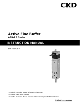
System Conguration
Basic setting items
1. Input the program from a personal computer.
2. Set required parameters the same way.
3. Set the appropriate gain.
Basic drive methods
1. A program to be executed is selected at the PLC.
2. Start signal is input at the PLC.
3. After operation, the driver outputs a positioning
completion signal.
Configuration (set model no. selection)
Name Quantity
Actuator body 1
Driver (with controller) 1
Motor cable and resolver cable 1 each
I/O connector, power supply connector, power supply connector open tool
* The motor cable connector is attached to the motor cable.
* For caution on connection methods, refer to operation manuals and
technical data.
Programming tool
• Startingadjustmentsupporttool"AXTools"isavailable.
(Windows version, free)
ABSODEXprogramsarecreated,parametersset,and
operation commands, etc., issued from the personal
computer.
Created programs can be saved.
PCcommunicationcable(model:AX-RS232C-9P)is
required.
Note
)
The PC communication cable is designed
specificallyforABSODEX.Youcannotuseacable
available on the market. If you do, the driver or PC
may be damaged.
Note
)
The PC communication cable is assumed to be
usedonlywhenadjustingtheconnection.
RemovethePCcommunicationcablefromCN1
during normal operation.
Note
)
When the PC returns from the sleep status,
communicationerrorsmayoccur,duetoun-
recognizingUSB-serialexchangecable.
Note
)
Downloadthelatestversionoftheadjustment
supporttool"AXTools"fromourwebsite.
* marked devices must be prepared by the user.
To comply with CE marking, parts below are required.
Refertouserinstructionsortechnicalmaterials(ABSODEX
MU type technical materials) for installation and wiring method.
Note 1) This is AC250 specifications. DC24V power supply is available
too.
Parts name Model No. Manufacturer
Noise filter NF2015A-OD Note1)
SOSHIN
ELECTRIC
CO.,LTD
Serge protector
R/A/ V-781BXZ- 4
R/A/ V-781BWZ-4
RSPD-250-Q4
RSPD-250-U4
OKAYA
ELECTRIC
INDUSTRIES
CO., LTD.

Intro 6
ABSODEX MINI type
AX6000MSeriesVariation
Torque (N•m)
Index accuracy
(sec.)
Repeatability
(sec.)
Page
1.2 3
±90 ±10 1
Drivers can be commonly
used.
The controller function
enables the actuator's
rotation angle, movement
time and timer, etc., to be
set as desired with an
NC program.
M code output, encoder
output, etc. can be used to
connect to an external PLC,
motion controller, etc.
5
Relatedpartsmodelnumbertable ............. Page9
Selection ................................................... Page 10
Safety precautions .............................. Page 13
ACTUATORCompatible driver

1
ACTUATORSPECIFICATIONS
ABSODEX
AX6000M
Series
Compatible function with free driver, actuator, and cable combinations
Diameter 80mm minimum size
Max. torque: 1.2Nm, 3Nm
Compatible driver: MU Type Driver
Items AX6001M AX6003M
Max. output torque N
・
m 1.2 3.0
Continuous output torque N
・
m 0.4 1.0
Max. rotation speed rpm 240
(Note 1)
Allowable axial load N 600
Allowable moment load N
・
m 5
Output shaft moment of inertia kg
・
m
2
0.00034 0.00059
Allowable load inertia moment kg
・
m
2
0.034 0.059
Index accuracy (Note 2) sec. ±90
Repeatability(Note2) sec. ±10
Output shaft friction torque N
・
m 0.13 0.22
Resolverresolution P/rev 540672
Motor insulation class A
Motor withstand voltage AC550V
1 minute
Motor insulation resistance 10MΩandover
DC500V
Ambient temperature 0
~
40°C
Ambient humidity 20
~
85%RHNofreezing
Storage temperature -10
~
65°C
Storage ambient humidity 20
~
90%RHNofreezing
Atmosphere Free of corrosive and explosive gases and dust
Weight kg 1.2 1.8
Runoutofoutputshaft(Note2) mm 0.03
Surface run out of output shaft (Note 2) mm 0.05
Degree of protection IP20
Note 1: Use 80 rpm or less during continuous rotary operation.
Note 2:
Fordetailsonindexprecision,repeatability,runoutofoutputshaft,andsurfacerunoutofoutputshaft,referto"Terminology"onpage11.
Speed and maximum torque characteristics
F
F
L
(Note) Moment load
M(N•m)=F(N)×L(m)
M : Moment load
F : Load
L : Distance from output shaft center
M(N•m)=F(N)×(L+0.02)(m)
M : Moment load
F : Load
L : Distance from output shaft flange
(Fig.a) (Fig.b)
L
ReadPrecautionsonpage13to17beforeuse.
AX6001M
AX6003M
[rpm]
300
200
100
50
250
150
0
0 0.5 1 1.5
[N•m]
* Graph shows the typical value during 24 VDC (Ambient temperature: 25 °C)
Continuous
movement
range
Intermittent
movement range
[rpm]
300
200
100
50
250
150
0
0 21 3 4
[N•m]
Continuous
movement
range
Intermittent
movement range
* Graph shows the typical value during 24 VDC (Ambient temperature: 25 °C)

2
How to order
AX6000M
Series
()
How to order
C
Mounting
base
E
Interface
specifications
B
Driver type
Model no.
A
Size
(Max. torque)
D
Cable length
Set model no. (actuator, driver, and cable)
Actuator model no. Driver model no. Cable model no.
A
Size
C
Mounting base
E
Interface
specifications
D
Cable length
Note:"DM04"ifthe
cable length is 4m
•Motorcable
•Resolvercable
Model Model no. of options
AX6 001 MU BS U0
Symbol
Descriptions
A
Size (Max. torque)
001 1.2N•m
003 3.0N•m
B
Driver type
MU With MU type driver
C
Mounting base
Blank
Standard (without mounting base)
BS
Electroless nickel plating
Surface treatment installation
AX6 M001 BS AX9000MU U0
Model no.
CustomordermodelsarenotcompliantwithCEnorRoHS.ContactCKDforeachorder.
DM04
E
Interface specifications
U0 Parallel I/O (NPN specifications)
U1 Parallel I/O (PNP specifications)
D
Cable length
DM02
2m
DM04
4m
DM06
6m
DM08
8m
DM10
10m
AX-CBLM8 DM04
AX-CBLR8 DM04

3
AX6000M
Series
AX6001M
Dimensions
Note 1: The actuator's origin may differ from that in the dimensional drawing.
The origin offset feature enables you to set the origin to any position you choose.
(Note) Min. bending range
outlet cable is 50mm.
80
80
4×ø4.8
Mounting base (Option)
4×C4
4.5 Depth 4
+0.2
0
ø80
0
-0.2
ø18h8
ø60h8
ø13
ø80
4×ø3.4
Connectorcasexing
4
+0.05
0
(ø18 reference)
37
P.C.D.74
(R)
45°
65
65
47
40
(3)
4
17
(95.4)
(3.5)
(3.5)
(3.5)
(16.5)
45°
(16.5)
18
34.4
41.4
(3.5)
80
87
(10)
7
P.C.D.70
Not available if the
optional mounting
base is installed.
4
+0.05
0
4.5 Depth 5
+0.2
0
(ø60 reference)
35
(R)
Outlet cable length 300mm
(Note) It is not a movable cable.
4×M4 Depth 8 (straight)
Platform for mounting
(Note) Fix the end of the cable sheath
when bending repeatedly.
RotarySection
(Including hollow section)
Fixed Section
4×M4 Depth 6.5 (straight)
For mounting rotary table

4
Dimensions
AX6000M
Series
Dimensions
AX6003M
Note 1: The actuator's origin may differ from that in the dimensional drawing.
The origin offset feature enables you to set the origin to any position you choose.
(Note) Fix the end of the cable sheath
when bending repeatedly.
Outlet cable length 300mm
(Note) It is not a movable cable.
RotarySection
(Including hollow section)
4×M4 Depth 6.5 (straight)
For mounting rotary table
(Note) Min. bending range outlet
cable is 50mm.
80
80
4×ø4.8
Mounting base (Option)
4×C4
4.5 Depth 4
+0.2
0
ø80
0
-0.2
ø18h8
ø60h8
Fixed Section
ø13
ø80
4×ø3.4
4
+0.05
0
(ø18 reference)
37
P.C.D.74
(R)
45°
65
65
67
60
(3)
4
17
(95.4)
(3.5)
(3.5)
(3.5)
(16.5)
45°
(16.5)
18
34.4
41.4
(3.5)
80
87
(10)
7
P.C.D.70
Not available if the
optional mounting
base is installed.
4
+0.05
0
4.5 Depth 5
+0.2
0
(ø60 reference)
35
(R)
Connectorcasexing
4×M4 Depth 8 (straight)
Platform for mounting

5
ABSODEX
MU
Type Driver
Common specifications Performance Specifications
Items Descriptions
Control shafts 1shaft,540,672pulses/1rotation
Angle setting unit ° (degrees), pulses, index numbers
Min. angle setting unit 0.001°, 1 pulse
Speed setting unit sec. rpm
Speed setting range 0.01~100s/0.11~240rpm
Equal divisions 1~255
Max. command value 7-digitnumberinput±9,999,999pulse
Timer 0.01sto99.99s
Program language NC language
Programming method
Data can be set with an interactive
terminal or personal computer, etc.,
usingtheRS-232Cport.
Operation Mode
Auto,job,singleblock,servoOFF,
pulse train input
Acceleration curve
<5 types>
Modified sine (MS),
modified constant velocity (MC,MC2),
modified trapezoidal (MT),
andtrapecloid(TR)
Status display
RUN:Normaloperatingstate
ALM2: Alarm 2 state
ALM1: Alarm 1 state
SERVO:Servostate
CHARGE:Chargestate
Communication
interface
RS-232Ccompliant
I/O signals
Refertotherelevantinterface
specifications page.
Program size Approx. 6000 characters (256 lines)
Electronic thermal Actuator overheat protection
Power supply
Actuator Model Driver Model
Rated input
current
Max. input
current
AX6001M,AX6003M AX9000MU 3.3A 10A
Interface specifications: Parallel I/O (NPN specifications)
Parallel I/O (PNP specifications)
Main features
Miniature/light weight (resin body)
Wiring is easy for the connector connection
How to order
Items Descriptions
Product name
MU Type Driver
AX9000MU
Power
voltage
Main
power
supply
DC24V±10%
Control
power
supply
DC24V±10%
Structure Integrated driver and controller
Ambient
temperature
0~50°C
Ambient
humidity
20~90%RH(nofreezing)
Operating
ambient
temperature
−10~65°C
Operating
ambient
humidity
20~90%RH(nofreezing)
Atmosphere No corrosive gases or powder dust.
Noise resistance
1000V(P-P),pulsewidth1μs,risingedge1ns,
impulse noise test, induction noise
(capacitive coupling)
Vibration
resistance
4.9m/s
2
Weight Approx. 0.5 kg
Degree of
protection
IP2X
AX9000MU U0
AX9000MU U1
Interfacespecications
U0:ParallelI/O(NPNspecications)
U1:ParallelI/O(PNPspecications)
CustomordermodelsarenotcompliantwithCEnorRoHS.ContactCKDforeachorder.
RefertoSafetyprecautionsonpage13to17beforeuse.

6
MU type driver
CN3 I/O circuit specifications
I/O circuit specifications
Descriptions
1 circuit
current
(mA)
Max.
points
(circuit)
Max.
current
(mA)
Max. current
consumption
(mA)
Input circuit 4 14 56
746Output circuit 30 18 540
Brakeoutput(BK+,BK-) 75 2 150
* The maximum number of simultaneous output points for the output circuits
is 14 out of 18.
CN3 output signal
Pin no. Signal Logic
33 M code output (bit 0) Positive
34 M code output (bit 1) Positive
35 M code output (bit 2) Positive
36 M code output (bit 3) Positive
37 M code output (bit 4) Positive
38 M code output (bit 5) Positive
39 M code output (bit 6) Positive
40 Mcodeoutput(bit7) Positive
41 In-positionoutput Positive
42 Positioning completion output Positive
43 Start input waiting output Positive
44 Alarm output 1 Negative
45 Alarm output 2 Negative
46 Intermediate index output 1/origin output Positive
47 Intermediate index output 2/servo state output Positive
48 Readyoutput Positive
49 Segment position strobe output Positive
50 M code strobe output Positive
CN3 Input signal
Pin no. Signal Logic Decision
1~2 External power supply input +24 V ± 10%
3~4 ExternalpowersupplyinputGND
5 Program number selection input (bit 0) Positive Level
6 Program number selection input (bit 1) Positive Level
7 Program number selection input (bit 2) Positive Level
8 Program number selection input (bit 3) Positive Level
9
Program number selection input 2nd digit/
program number selection input (bit 4)
Positive
Edge
Level
10
Program number selection input 1st digit/
program number selection input (bit 5)
Positive
Edge
Level
11 Resetinput Positive Edge
12 Home Positioning Instruction Input Positive Edge
13 Start input Positive Edge
14
Servo ON input/program stop input
Positive
Level
Edge
15 Continuous rotation stop input Positive Edge
16
Answer input/position deviation counter reset
Positive Edge
17 Emergency Stop Input Negative Level
18 BrakeReleaseInput Positive Level
CN3 pulse train input signal
Pin no. Signal
19 PULSE/UP/A phase
20 -PULSE/-UP/-Aphase
21 DIR/DOWN/Bphase
22 -DIR/-DOWN/-Bphase
CN3 encoder output signal (incremental)
Pin no. Signal
23 A phase (line driver output)
24 -Aphase(linedriveroutput)
25 B phase (line driver output)
26 -Bphase(linedriveroutput)
27 Zphase(linedriveroutput)
28 -Zphase(linedriveroutput)
Parallel I/O (NPN specifications)
DRIVERSPECIFICATIONS
Input circuit
Output circuit
1,2-pin +24V±10%
33 to 50 pin
Load
3,4-pin
1,2-pin +24V±10%
5 to 18 pin
19,21-pin
20,22-pin
Rated voltage 5V±10%
Max. input frequency
Line driver 1Mpps
Open collector 250Kpps
240Ω
510Ω
Rated voltage 24V±10%
Rated current 30mA (MAX)
Rated voltage 24V±10%
Rated current 4mA (at 24VDC)
Pulse train Input circuit
23,25 to 27 pin
24,26 to 28 pin
Output type:line driver
Use line driver: DS26C31
Recommended line receiver: DS26C32 or equivalent
Encoder Output Circuit

7
MU type driver
CN3 I/O circuit specifications
I/O circuit specifications
Descriptions
1 circuit
current
(mA)
Max.
points
(circuit)
Max.
current
(mA)
Max. current
consumption
(mA)
Input circuit 4 14 56
746Output circuit 30 18 540
Brakeoutput(BK+,BK-) 75 2 150
* The maximum number of simultaneous output points for the output circuits
is 14 out of 18.
CN3 output signal
Pin no. Signal Logic
33 M code output (bit 0) Positive
34 M code output (bit 1) Positive
35 M code output (bit 2) Positive
36 M code output (bit 3) Positive
37 M code output (bit 4) Positive
38 M code output (bit 5) Positive
39 M code output (bit 6) Positive
40 Mcodeoutput(bit7) Positive
41 In-positionoutput Positive
42 Positioning completion output Positive
43 Start input waiting output Positive
44 Alarm output 1 Negative
45 Alarm output 2 Negative
46 Intermediate index output 1/origin output Positive
47 Intermediate index output 2/servo state output Positive
48 Readyoutput Positive
49 Segment position strobe output Positive
50 M code strobe output Positive
CN3 Input signal
Pin no. Signal Logic Decision
1~2 ExternalpowersupplyinputGND
3~4 External power supply input +24 V ± 10%
5 Program number selection input (bit 0) Positive Level
6 Program number selection input (bit 1) Positive Level
7 Program number selection input (bit 2) Positive Level
8 Program number selection input (bit 3) Positive Level
9
Program number selection input 2nd digit/
program number selection input (bit 4)
Positive
Edge
Level
10
Program number selection input 1st digit/
program number selection input (bit 5)
Positive
Edge
Level
11 Resetinput Positive Edge
12 Home Positioning Instruction Input Positive Edge
13 Start input Positive Edge
14
Servo ON input/program stop input
Positive
Level
Edge
15 Continuous rotation stop input Positive Edge
16
Answer input/position deviation counter reset
Positive Edge
17 Emergency Stop Input Negative Level
18 BrakeReleaseInput Positive Level
CN3 pulse train input signal
Pin no. Signal
19 PULSE/UP/A phase
20 -PULSE/-UP/-Aphase
21 DIR/DOWN/Bphase
22 -DIR/-DOWN/-Bphase
CN3 encoder output signal (incremental)
Pin no. Signal
23 A phase (line driver output)
24 -Aphase(linedriveroutput)
25 B phase (line driver output)
26 -Bphase(linedriveroutput)
27 Zphase(linedriveroutput)
28 -Zphase(linedriveroutput)
Parallel I/O (PNP specifications)
Driver accessories
Model No. Specifications CN3 connector CN4 connector
AX9000MU-U0 Parallel I/O (NPN)
Model:10150-3000PE(plug)
Model:10350-52A0-008(shell)
Sumitomo 3M
Power supply connector
04JFAT-SBXGF-I
Open tool
J-FAT-OT
Made by J.S.T. Mfg. Co.,Ltd.
AX9000MU-U1 Parallel I/O (PNP)
Refertohowtoorderlistforadditionalpartorder.
Ratedvoltage24V±10%
Ratedcurrent4mA(at24VDC)
5 to 18 pin +24V±10%
1,2-pin
20,22-pin
19,21-pin
23,25to27pin
Ratedvoltage5V±10%
24,26 to 28 pin
240Ω
510Ω
3,4-pin+24V±10%
33 to 50 pin
1,2-pin
Load
Input circuit Pulse train Input circuit
Output circuit Encoder Output Circuit
Max. input frequency
Line driver 1Mpps
Open collector 250Kpps
Output type:line driver
Use line driver: DS26C31
Recommendedlinereceiver:DS26C32orequivalent
Ratedvoltage24V±10%
Ratedcurrent50mA(MAX)

8
MU type driver
Parallel I/O (NPN specifications)
Note1)Determineadimensionthatismorethansufcientforthecablethatyouareusing.
Panel description
Installation dimensions
• TheABSODEXdriverisnotdustprooforwaterproof.
Protect the driver so that dust, water, oil, etc. do not enter the driver.
• IfyouareinstallingtheABSODEXdriverinthecontrolbox,makesurethatthetemperatureinsidetheboxdoesnot
exceed 50°C, and install the driver as shown in the following diagram to secure space around it.
Dimensions
ø5 penetration
Dimensions/Installation dimensions/Panel description
Normal driving LED
CN1RS-232Cconnector
CN2 resolver cable connector
CN3 I/O connector
TB1 Brake terminal
Alarm 2 LED
Alarm 1 LED
Servo state LED
Charge state LED
Actuator output
terminal
FGterminal
2×M4
Control power supply
Main power supply
Parallel I/O (PNP specifications)
Normal driving LED
CN1RS-232Cconnector
CN2 resolver cable connector
PNP driver display
CN3 I/O connector
TB1 Brake terminal
Alarm 2 LED
Alarm 1 LED
Servo state LED
Charge state LED
Actuator output
terminal
FGterminal
2×M4
Control power supply
Main power supply
40
30 40 30
Note 1
(100)
20
(100)
80
2.5
5
170
180
160 5050
160
(R2.5)
5
20

Resolvercable 60mm
Motor cable 90mm
9
AX6000M
Series
Safety precautions
Fix the cable sheath near the actuator connector, where a cable is bent repeatedly.
The cables are not movable cables. Be sure to fix the cables in place at the connectors so that they do not move.
Do not lift up the body by the cable or apply excessive force to the cable as the cable may break.
When connecting the cable, insert the connector securely to the back. Tighten the connector's set screws and
fixing screws.
Do not modify the cable by cutting or extending it. Failure to observe this could result in faults or malfunctions.
ForcablelengthL,refertothecablelengthsin"Howtoorder".
Cable specifications
Minimum cable bending radiusCable dimensions
HowtoorderABSODEXrelatedparts
Relatedparts
Product Applicable model Model no.
PC communication cable (2m) AXSeries AX-RS232C-9P
Mounting base
Product Applicable model Model no.
Mounting base AX6001M,AX6003M AX-AX6000-BASE-BS
Power
Product Applicable model Model no.
24 VDC Power supply AX9000MU
AX-PWR-SWD100P-24-CNote1)
(Note 1) If you purchase the above model from our company, the power supply input cable (1m) and power supply output cable (1m)
are included.
* The parts listed on this page can be purchased from CKD.
Noise filter
Product Applicable model Model no.
Noise filter for power supply (Single phase AC250V/15A) Note 1) AXSeries AX-NSF-NF2015A-OD
Serge protector (For 3 phases) Note 4) AXSeries AX-NSF-RAV-781BXZ-4
(Note 1) This is AC250V specifications. DC24V power supply is available too.
(Note 2) Parts indicated on this page are the list of parts we provide.
(Note 3) To use them being compatible with EU standards (CE marking), noise filter for electric power and serge protector etc. are
required.Refertouserinstructionsortechnicalmaterials(ABSODEXAXseriesMUtypetechnicalmaterials)formoredetails.
Other components
Product Applicable model Model no.
I/O connector (CN3: for parallel I/O) AXSeries(-U0,U1) AX-CONNECTOR-MDR
Power supply connector set (with open tool) AX9000MUSeries AX-CONNECTOR-04JFAT-KIT
L (Cable length)
(93)
(16)
(7.1)
(11.4)
(17.3)
(15)
(29.1)
(7.2)
(21.4)

AX
Series
10
ABSODEX selection guide specifications check sheet
Table direct drive
(Note) Contact CKD for chain drives and gear drives.
■ Operating conditions
1. Index 2. Oscillator
Movement angle Ψ (°) or no. of indexes
Movement time t1 (sec.)
Cycle time t0 (sec.) cycle time=moving time+dwelling time
(Note) Index time is movement time + settling time.
The settling time differs according to the working condition, but generally is between 0.025 and 0.2s.
Your company name
Division
TEL
Your name
FAX
■ Load conditions
Table
Material 1. Steel 2. Aluminum
Outline Dt(mm)
Plate thickness
ht(mm)
Weight m1(kg)
Workpiece
Quantity nw (pc.)
Max. weight mw (kg/pc.)
Installation center Dp(mm)
Pallet fixture
Quantity np (pc.)
Max. weight mp (kg/pc.)
■ Others
Installation attitude
1. Horizontal (Fig.2) 2.Vertical (Fig. 3)
Extemal job
1. None 2. available
(Note) Eccentric load caused by gravity from vertical
installation, extemal load caused by caulking work.
Dial plate support form bottom
1. None 2. available
Coefficient of friction μ
Work radius Rf(mm)
Device rigidity
1. High 2. Low (Note)
(Note) When using a spline, when unit cannot be fixed
directly onto the device (Fig. 4), when there is
a mechanism such as a chuck on the table.
Extension with table shaft
1. None
2. available (Fig. 5)
Actuator movement
1. None 2. available
(Note) When actuator is mounted on X-Y table or vertical
mechanism, etc., and mounted actuator moves.
(Note) If 2 is selected for any item, contact CKD.
(Fig. 4) Installation rigidity: Low
(Note) Attach system outline and reference drawings so that the
optimal model can be selected.
(Fig. 1) Load conditions
(Fig. 2) Installation orientation: Horizontal (Fig. 3) Installation orientation: Vertical
(Fig. 5) Extension with shaft
Dp
Rf
μ
Dt
ht
Pallet fixture
■ Use conditions, environmental conditions (Optional)
Actuator ambient temperature (°C)
Motor cable length (m)
Driver ambient temperature (°C)
DC24V power supply cable length (m)
DC24V power supply coil diameter (mm
2
)
DC24V power supply voltage accuracy (%)
DC24V line point of contact quantity (pc.)
DC24V line point of contact resistance (MΩ / pc.)
* You can do a more rigorous selection by filling in this field.
* With a power supply cable 1.25mm² or more, please use one as short (recommended length 1m or less) as possible.
* If the output voltage is low in a power supply with voltage adjustment, please adjust it to 24V and use it.
Workpiece
Selection

AX
Series
11
Terminology
6
5
4
3
2
1
+5″
-10″
-27″
-18″
-7″
Reference station
Example of index accuracy measurement
Index
precision
±16
0
+5″
-10″
-27″
-18″
-7″
1
2
3
4
5
6
Measured
value
Measuring
position
TheABSODEXindexprecisionisthedifferencebetweenthetarget
position set by an NC program and the actual stop position.
The target position is an angle (s) from the reference station
(origin return position).
As shown in the diagram on the right, the index precision is calculated
from the maximum and minimum values of the differences between
the target positions and the actual stop positions. Measurement is
expressed in terms of the width using positive and negative seconds,
as shown on the right.
A high precision encoder is used for the angular measurement.
Repeatabilityexpressesthedeviationintheanglesofthestop
positions measured repeatedly under the same conditions for the
same target position. It is expressed as an angle in seconds.
Depending on the precision characteristics that the machine requires,
repeatability and index precision must be used separately.
Terminology
Index accuracy
Repeatability
* sec. A unit used to express angles (degrees, minutes, and seconds).
1 degree = 60 minutes = 3600 seconds
Theout-of-roundnessofthespigotsideofthetableinstallationsurface.
Runoutofoutputshaft
Face deflection
Theout-of-roundnessofthetableinstallationsurface.
Run out of output shaft
Surface run out of output shaft

12

13
Always read this section before use.
Safety Precautions
When designing and manufacturing devices using direct drive actuator, the manufacturer has an obligation
to manufacture a safe device, and to check that the safety of the device's mechanical mechanism and the
system operated by the electrical control that controls the device is secured.
Product selection, its usage and handling, as well as adequate maintenance management are important
in order to safely use CKD products.
To ensure equipment safety, please follow the warnings and precautions.
Please check that equipment safety is ensured and manufacture safe equipment.
Warning
This product is designed and manufactured as a general industrial machine part.
Itmustbehandledbyanoperatorhavingsufcientknowledgeandexperienceinhandling.
Use within the product's specific specification range.
Itcannotbeusedoutsideofproduct-specificspecifications.Donotattempttomodifyoradditionally
machine the product.
This product's applied scope is for use as equipment and parts for general industrial machinery.
Therefore, outdoor use as well as the following conditions and environments shall be considered outside
of the applied scope.
(If you consult CKD upon adoption and consent to CKD product specification, it will be applicable;
however, safeguards should be adopted that will circumvent dangers in the event of failure.)
Use for special applications including nuclear energy, railway, aircraft, marine vessel, vehicle, medical
equipment, equipment, or applications coming into contact with beverage or food, amusement
equipment, emergency shutoff circuits, press machine, brake circuits, or for safeguard.
Usage in applications that especially require safety, such as those that greatly affect humans and property.
Observe corporate standards and regulations, etc., related to the safety of device design.
Do not remove devices until safety is confirmed.
Inspect and service the machine and devices after securing the safety of the system, such as by
turning off the peripheral devices and other devices connected to this product.
Exercise caution when inspecting, maintaining, and handling the product, as high temperature and
charged parts can be present even when operation is stopped.
Before starting device inspection or maintenance, turn off device power and other power to related
devices, release compressed air, and check leakage current.
Observe warnings and cautions in the instruction manual of each product.
Do not rotate the actuator outputs shaft by 30 rpm or more while power is off.
The driver could fail or electrical shock result from actuator power generation.
If the servomotor is turned off (including emergency stop or alarm) or brakes are turned off while a
rotational force, such as gravity, is applied, the output shaft may rotate by rotational force.
Conduct these operations flat where rotational force is not applied, or confirm safety before starting.
Unexpectedmovementmayoccurduringgainadjustmentortestoperation,sokeephands,etc.,away
from the outputs shaft. When conducting operations with the actuator not visible, confirm before
starting that it is safe even if the outputs shaft turns.
The brakes of the type with brake do not necessarily hold the outputs shaft completely in all situations. If safety must
be ensured, such as in maintenance with an application that rotates the output shaft in unbalanced mode, or when
stoppingthemachineforalongtime,itmaynotbesufcienttostoptheshaftwithbrakesalone.Makesureequipment
ismaintainedbalancedorprovideamechanicallockingmeans.Usethesystematorprovideamechanicallock.
It may take several seconds to stop in an emergency, depending on rotation speed and load.
To prevent electric shock, observe warnings and cautions.
High voltage is supplied to the terminal block at the driver's front panel and actuator output terminal.
For a terminal block, be sure to install the supplied terminal cover before operation. Do not touch the
terminal block while power is on. Do not touch the terminal block while power is on. Even after the
power is turned off, a high voltage is applied until the charge accumulated in the internal capacitor is
discharged. Wait at least five minutes after turning the power off before touching these sections.
In work with side cover off, such as for maintenance and inspection or changing driver switches, turn
power off and wait at least five minutes before starting work because a risk of electrical shock from
high voltage exists.
Do not connect or disconnect connectors while power is on. Misoperation, faults, or electrical shock may occur.
Before restarting a machine or system, check that measures are taken so that parts do
not come off.
/