Page is loading ...

PCI-M324 User Guide
www.deltaww.com
Industrial Automation Headquarters
Delta Electronics, Inc.
Taoyuan Technology Center
18 Xinglong Road, Taoyuan District,
Taoyuan City 33068, Taiwan (R.O.C.)
TEL: 886-3-362-6301 / FAX: 886-3-371-6301
Asia
Delta Electronics (Shanghai) Co., Ltd
No.182 Minyu Road, Pudong Shanghai,
People's Republic of China
Post code : 201209
TEL: 86-21-68723988 / FAX: 86-21-6872-3996
Customer Service: 400-820-9595
Delta Electronics (Japan), Inc.
Tokyo Ofce
2-1-14 Minato-ku Shibadaimon,
Tokyo 105-0012, Japan
TEL: 81-3-5733-1111 / FAX: 81-3-5733-1211
Delta Electronics (Korea), Inc.
1511, Byucksan Digital Valley 6-cha, Gasan-dong,
Geumcheon-gu, Seoul, Korea, 153-704
TEL: 82-2-515-5303 / FAX: 82-2-515-5302
Delta Electronics Int’l (S) Pte Ltd.
4 Kaki Bukit Ave 1, #05-05, Singapore 417939
TEL: 65-6747-5155 / FAX: 65-6744-9228
Delta Electronics (India) Pvt. Ltd.
Plot No 43 Sector 35, HSIIDC
Gurgaon, PIN 122001, Haryana, India
TEL: 91-124-4874900 / FAX : 91-124-4874945
Delta Electronics (Thailand) Public Company Limited
909 Soi 9, Moo 4,Bangpoo Industrial
Estate(Epz) Pattana 1rd., Tambol Phraksa
Amphur Muang, Samutprakarn 10280 Thailand
TEL: 66(0)2-709-2800
Delta Energy Systems Austral Pty Ltd.
Unit 20-21, 45 Normanby rd, Notting Hill Vic 3168, Australia
TEL: 61-3-9543-3720
Americas
Delta Products Corporation (USA)
Raleigh Ofce
P.O. Box 12173, 5101 Davis Drive,
Research Triangle Park, NC 27709, U.S.A.
TEL: 1-919-767-3800 / FAX: 1-919-767-3969
Delta Greentech (Brasil) S.A.
Sao Paulo Ofce
Rua Itapeva, 26 - 3° andar Edicio Itapeva One-Bela Vista
01332-000-São Paulo-SP-Brazil
TEL: 55-11-3568-3855 / FAX: 55-11-3568-3865
Delta Electronics Int. Mexico
Mexico Ofce
Via Dr. Gustavo Baz 2160, La Loma
C.P. 54060, Estado de México
TEL: 55-2628-3015
*We reserve the right to change the information in this manual without prior notice.
EMEA
Delta Electronics (Netherlands) B.V.
Eindhoven Ofce
De Witbogt 20, 5652 AG Eindhoven, The Netherlands
TEL: 31 (0) 40-8003800 / FAX: 31 (0) 40-8003898
MAIL: [email protected]
MAIL: [email protected]
Delta Energy Systems (France) S.A
ZI du bois Chaland 2 15 rue des Pyrénées,
Lisses 91056 Evry Cedex
MAIL: [email protected]
Delta Energy Systems (Spain) S.L.
Ctra. De Villaverde a Vallecas, 265 1º Dcha Ed.
Hormigueras – P.I. de Vallecas 28031 Madrid
C/Llul, 321-329 (Edif. CINC) | 22@Barcrelona | 08019 Barcelona
MAIL: [email protected]
Delta Energy Systems Srl (Italy)
Via Senigallia 18/2 – 20161 Milano (MI)
Piazza Grazioli 18 – 00186 ROMA
MAIL: [email protected]
Delta Energy Systems (Germany) GmbH
Coesterweg 45, D-59494 Soest
MAIL: [email protected]
Delta Energy Systems LLC (CIS)
Vereyskaya Plaza II, ofce 112 Vereyskaya str.
17 121357 Moscow
MAIL: [email protected]
Delta Greentech Ltd. (Turkiye)
Şerifali Mevkii Barbaros Bulvari Söyleşi Sokak
No:19 K:1 Yukari Dudullu 34775 Ümraniye
İstanbul Sarigazi V.D 2740624765
MAIL: [email protected]
Delta Energy Systems (AG Dubai BR)
P.O. Box 185668, Gate 7, 3rd Floor, Hamarain Centre,
Dubai, United Arab Emirates
MAIL: [email protected]

November, 2017 i
Preface
Thank you for purchasing this product. This user guide provides hardware specifications and other
information about the PCI-M324 motion control card.
This user guide includes:
Product Overview
Installation
Signal Connection Interface
Terminal Board
Wiring
EzDMC Functions
Product features of the PCI-M324 motion control card
PCI-M324 is a motion control card with DSP (Digital Signal Processor) as the core design,
and the controlling method between the servo drive is with the use of pulse output. Through the
high-performance chip to calculate the motion trajectory, it provides synchronous timing control for
multiple axes and DI/O processing functions. With the general motion software library and
diagnostic tool for the graphic interface, program development becomes easier, which also
simplifies the system construction and troubleshooting for users.
How to use this user guide
You can refer to the information in this user guide when using the PCI-M324 motion control card.
This user guide provides the hardware electrical specifications and wiring examples of the
PCI-M324 card. Prior to connecting to external devices, please read this user guide to understand
the features of each I/O pin of the PCI-M324 card and the hardware configuration.
Delta technical services:
Please consult your Delta equipment distributor or Delta Customer Service Center if you encounter
any problems.

ii November, 2017
(This page is intentionally left blank.)

November, 2017
Table of Contents
Product Overview
1.1 Function description ·························································································· 1-2
1.2 Specifications ·································································································· 1-3
1.3 Safety precautions ···························································································· 1-4
1.4 Operational safety instructions ············································································ 1-4
1.5 Supported software ·························································································· 1-5
1.6 Application development ···················································································· 1-6
Installation
2.1 Product packaging and accessories ····································································· 2-2
2.2 PCB diagram ··································································································· 2-3
2.3 Hardware installation ························································································ 2-4
2.3.1 Hardware setting ························································································ 2-4
2.3.2 PCI slot selection ······················································································· 2-4
2.3.3 Installation procedure ·················································································· 2-4
2.3.4 Troubleshooting ························································································· 2-4
2.4 Driver software installation ················································································· 2-5
2.5 Connector pin description··················································································· 2-6
2.5.1 CN1: I/O signal port ···················································································· 2-6
2.5.2 CN3: position comparison triggering signal port ················································ 2-9
2.5.3 RSW1: switch for card ID number setting ······················································ 2-10
2.5.4 JP1: select jumper according to input signal type (NPN / PNP) ··························· 2-11
2.5.5 JP2: internal pulse (DDA) 5V ground and external +24V ground signal jumper ······ 2-12
Signal Connection Interface
3.1 Operation interface ··························································································· 3-2
3.1.1 Mechanical DI/O interface ············································································ 3-2
3.1.2 Servo drive DI/O interface ············································································ 3-9
3.1.3 Servo drive pulse I/O interface ···································································· 3-15
3.1.4 Position comparison triggering signal output interface ······································ 3-18
3.1.5 Position latch signal input interface ······························································ 3-21

November, 2017
Terminal Board
4.1 DB-100S general terminal board ·········································································· 4-2
4.2 DB-M324 adapter board with signal indicator·························································· 4-3
Wiring
5.1 Terminal board wiring example ············································································ 5-2
Hardware Configuration API
6.1 Introduction to EzDMC functions·········································································· 6-2
6.2 Operate M324 functions with EzDMC ··································································· 6-3
6.3 Find PCI-M324 card ·························································································· 6-3
6.4 4-axis motion function control ·············································································· 6-4
6.5 Function description of File and Simulation ···························································· 6-7

November, 2017 1-1
Product Overview
PCI-M324 is a 4-axis pulse type motion control card for 4-axis servo or stepping motion
control. This chapter includes the function descriptions, specifications, safety
instructions, and other information of the PCI-M324 motion control card to help you
quickly understand the product features.
000
1.1 Function description ··········································································· 1-2
1.2 Specifications ··················································································· 1-3
1.3 Safety precautions ············································································· 1-4
1.4 Operational safety instructions ····························································· 1-4
1.5 Supported software ············································································ 1-5
1.6 Application development ····································································· 1-6

Product Overview PCI-M324 User Guide
1-2 November, 2017
1
1.1 Function description
PCI-M324 is a 4-axis motion control card using a standard PCI interface. It generates
high-frequency control pulses (3.2 MHz) to control the stepper motor or servo motor. With the
4-axis motion control function, it provides 2-axis circular interpolation motion control, 4-axis linear
interpolation, or continuous interpolation motion control at constant speed. Multiple PCI-M324
motion control cards can operate simultaneously in one system and perform motion control
functions. To allow users to quickly learn to operate the control card, Delta developed software
auxiliary tools to help you complete the application development and wiring test work in the
shortest possible time.
The four main axis controls of the PCI-M324 motion control card are built-in with the incremental
encoder interface, which can correct the incorrect mechanical data transmission. PCI-M324 is
equipped with precise and fast-motion position comparison and triggering functions, and does
not take up additional CPU resources. In addition, the interfaces for the contacts, servo motor
drive control, and general I/O signal control have a very intuitive design for wiring, so that
beginners can quickly get hold of the motion control basics and reduce product losses for system
integrators due to wiring errors. The motion control function includes acceleration / deceleration
of linear motion and S-curve control, arbitrary 2-axis circular interpolation, 2- / 3-axis linear
interpolation, continuous motion, 35 homing modes, etc. When executing these complex motion
control functions, your CPU computing resources can deal with other applications without being
occupied by the motion control functions.

PCI-M324 User Guide Product Overview
November, 2017 1-3
1
1.2 Specifications
Product features
(1) Maximum 3.2 MHz, 4-axis pulse output
(2) Linear, circular, and continuous interpolations
(3) Programmable acceleration / deceleration time
(4) Programmable pulse output and interrupt functions
(5) Position comparison and signal trigger
Motion control specifications
(1) Pulse output control: OUT / DIR, CW / CCW, AB Phase
(2) Pulse output rate: maximum 3.2 Mpps
(3) Total number of pulse signals: 32 bits (±2,147,483,648 pulses)
(4) Homing modes: 35 types
(5) Speed curve control: T-curve and S-curve
(6) Interpolation modes: linear, circular, and continuous
(7) Total number of counter signals: 32-bit up / down counter x 4
(8) Position latch input: LTC x 4
(9) Position compare output: CMP x 2
(10) Incremental encoder input: ±EA x 4, ±EB x 4
(11) Encoder Z-phase signal input: ±EZ x 4
(12) Mechanical DI interface: PEL x 4, MEL x 4, ORG x 4, SLD x 4
(13) Servo drive interface: ALM x 4, RDY x 4, SVON x 4, INP x 4, ERC x 4
(14) General input point: IN x 4
(15) General output point: OUT x 4
(16) I/O pin type: optically isolated with 2.5 KV
RMS
on all 100-pin SCSI
General electrical specifications
(1) PCI specification: 2.2; 32-bit support, 3.3 / 5 V
DC
operation type
(2) Power consumption: typical +5 V
DC
at 0.5A
(3) Operating temperature: 0°C - 50°C (32°F - 122°F)

Product Overview PCI-M324 User Guide
1-4 November, 2017
1
1.3 Safety precautions
To avoid electric shock resulting in serious damage, please check the following precautions
before installing the equipment:
(1) Before moving the host computer, please unplug the computer power cord from the
power outlet.
(2) When adding hardware to the system, please connect the device's signal cable before
connecting the power cord; when removing hardware from the system, please disconnect
the device's signal cable before disconnecting the power cord. If possible, turn off the
computer's power supply before installing the hardware.
(3) Before connecting or disconnecting any signal cables from the motherboard, please make
sure all power cables are unplugged.
(4) Before using the interface card or expansion card, it is recommended that you first seek
professional assistance, as these devices may interfere with the grounded circuits.
(5) Please make sure the voltage power supply unit is adjusted to the standard level used in
the country / region where the machine is installed. If you are unsure of the supplying
voltage of the given area, please contact the local power company for more information.
(6) If the power supply unit is damaged, do not repair it by yourself. Please contact technicians
or distributors for assistance.
1.4 Operational safety instructions
Before you install a hardware device, please review the information provided in this user guide.
(1) Before using the product, make sure all cables and power cords are properly connected.
If you find any major defects, please contact your distributor as soon as possible.
(2) To avoid short circuit, please put away all unused screws, paper clips, and other parts.
Please do not leave them on the motherboard or the host computer.
(3) Dust, humidity, and severe temperature changes can affect the product lifespan.
Thus, avoid placing the product in places with these conditions.
(4) Do not place the host computer on an unstable surface.
(5) If you have any technical questions regarding the use of this product, please contact a
certified technician for assistance.

PCI-M324 User Guide Product Overview
November, 2017 1-5
1
1.5 Supported software
Programming Library
You can develop relevant applications on the Windows XP / 7 platform. By categorizing the
motion control related API into usage condition and application, and with the programming guide,
you can quickly develop relevant applications.
EzDMC
EzDMC is an auxiliary software that can be operated on Windows XP / 7. Prior to developing the
application, you can use the auxiliary program to check and set the hardware contact logic status
to make sure that the external wiring is correct. You can also use this program to control the
wired servo drive and motor to assist in the adjustment and testing of the machine. In the initial
stage of using PCI-M324 for program development, you can also use EzDMC to simplify the
parameter setting and functional test verification, which can help new users to reduce the time
required for learning and development.

Product Overview PCI-M324 User Guide
1-6 November, 2017
1
1.6 Application development
Software application development structure
Window XP / 7
HM1 / Programming
BCB++ / VB /
VC++/C#
EzDMC
Motion API
Master station
PCI-M324
SCSI 100 Pins
Cable
Terminal board
Motor #1
Motor #2
Motor #3
Motor #4
Flow chart
The following is a flow chart for the application development process to help you understand
how to use this user guide for the connection and reference of the program development.
The connection between chapters and the sequence, as well as the development of the
application, can be seen in the flow chart.
Start
1. Install hardware
2. Select and set jumper
wire
3. Connect all wiring
Activate EzDMC:
set system parameter
Activate EzDMC:
verify system parameter
setting
Use the control card
function library to
develop the application
Is the system
working properly?
No
Yes
End
Refer to PCI-M324
Function Library
Programming
Guide for details
Refer to Chapter 6
for details
Refer to Chapter 6
for details
Refer to Chapters 2, 3,
4, and 5 for details

November, 2017 2-1
Installation
This chapter describes how to install the PCI-M324 motion control card. Please follow
the installation procedure below.
000
2.1 Product packaging and accessories ······················································· 2-2
2.2 PCB diagram ···················································································· 2-3
2.3 Hardware installation ·········································································· 2-4
2.3.1 Hardware setting .....................................................................................2-4
2.3.2 PCI slot selection ....................................................................................2-4
2.3.3 Installation procedure ..............................................................................2-4
2.3.4 Troubleshooting ......................................................................................2-4
2.4 Driver software installation ··································································· 2-5
2.5 Connector pin description ···································································· 2-6
2.5.1 CN1: I/O signal port .................................................................................2-6
2.5.2 CN3: position comparison triggering signal port .......................................2-9
2.5.3 RSW1: switch for card ID number setting .............................................. 2-10
2.5.4 JP1: select jumper according to input signal type (NPN / PNP) .............. 2-11
2.5.5 JP2: internal pulse (DDA) 5V ground and external +24V ground
signal jumper ........................................................................................ 2-12

Installation PCI-M324 User Guide
2-2 November, 2017
2
2.1 Product packaging and accessories
The package should contain the following items:
Standard
Advanced 4-axis servo or stepping PCI-M324 motion control card x 1
PCI-M324 driver CD-ROM x 1
PCI-M324 User Guide x 1
Optional
Motion control terminal block
SCSI 100-pin signal connector cable
If there are missing or damaged standard parts, please contact the distributor for the
replacement parts. Please keep the packaging material in case of future shipping needs.

PCI-M324 User Guide Installation
November, 2017 2-3
2
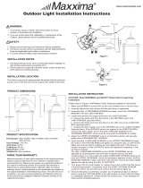
2.2 PCB diagram
This is the general structure of the PCI-M324 motion control card displaying the positions for
CN1, JP1, JP2, CN3, and RSW1.
Description of each connector on the PCI-M324 card is as follows:
Name
Function
CN1
SCSI 100 pins, 4-axis motion control I/O signal port
CN3
Position comparison triggering signal port
JP1
Select jumper according to input signal type (NPN / PNP)
JP2
Pulse output I/O and external +24V ground signal jumper
RSW1
Card ID switch

Installation PCI-M324 User Guide
2-4 November, 2017
2
2.3 Hardware installation
2.3.1 Hardware setting
The PCI-M324 is a standard Plug and Play expansion device for PCs. Whether the use of
memory space configuration or I/O port configuration, or other basic system required functions,
these are configured by the BIOS of the PC system. You do not need to set the hardware.
2.3.2 PCI slot selection
When your PC system is built-in with ISA and PCI expansion slots, please do not insert the
PCI-M324 card into the ISA expansion slot. In addition to the shape not matching, this product is
designed for PCI compatible devices, thus it can only function when inserted into a standard PCI
expansion slot.
2.3.3 Installation procedure
Please read this user guide carefully and adjust the functions of RSW1, JP1, and JP2 according
to the requirements before installation to meet your system development needs.
(1) Turn off the power. Make sure that the PC power supply is completely disconnected and turn
off the power for the connected devices, such as the printer, modem, and screen.
(2) Remove the cover of your PC. Install the PCI-M324 card only in the standard PCI expansion
slot. Please do not install it in the ISA or EISA expansion slot.
(3) Before you take out the card from the packaging, please neutralize the static electricity that
might be on your body to avoid damaging the product.
(4) Insert the PCI-M324 card into the appropriate PCI standard expansion slot, then tighten the
screws to fix the card onto the PC expansion slot.
(5) Make sure to disconnect the power supply before removing the PCI-M324 card.
2.3.4 Troubleshooting
If the system cannot start properly, please turn off the system first and disconnect the power.
Remove the cover of your PC. Next, make sure the PCI-M324 card is properly installed, such as
if the screws are loose or if the card is detached from the PCI expansion slot. Remove the
PCI-M324 card from the PCI slot and restart the PC to check that the PC system is working
properly. If the PC system is working properly, please reinstall the PCI-M324 card by following
the installation procedure in Section 2.3.3. If the system still cannot start properly, please contact
your distributor for assistance.

PCI-M324 User Guide Installation
November, 2017 2-5
2
2.4 Driver software installation
Please note the following before installing the driver and application software:
(1) The driver for this product is currently only compatible with Windows XP / 7. Before installing
this product, please make sure that the operating system meets the requirement of this
product.
(2) Insert the Autorun driver CD-ROM into your CD-ROM drive and let the system automatically
run the setup program.
(3) When the setup program is launched, please follow the instructions for installing the
product-related driver and auxiliary application.
(4) After the product-related driver and auxiliary application are installed, restart the operating
system to ensure that the driver is installed. Please also make sure that the auxiliary
application works properly after you restart the operating system.

Installation PCI-M324 User Guide
2-6 November, 2017
2
2.5 Connector pin description
This section provides detailed specifications and functions of the PCI-M324 motion control card
I/O signal terminals.
(1) CN1 connector (male); (2) CN1 I/O signal connector (female)
2.5.1 CN1: I/O signal port
Pin
Mark
I/O
Description
Pin
Mark
I/O
Description
1
24V
Power +24V / 200 mA
51
24V
Power +24V / 200 mA
2
EGND
24V ground signal
52
EGND
24V ground signal
3
EMG
I
Emergency stop signal
53
EMG
I
Emergency stop signal
4
MEL_1
I
1
st
mechanical negative
limit signal
54
MEL_3
I
3
rd
mechanical negative
limit signal
5
PEL_1
I
1
st
mechanical positive
limit signal
55
PEL_3
I
3
rd
mechanical positive
limit signal
6
ORG_1
I
1
st
origin position signal
56
ORG_3
I
3
rd
origin position signal
7
SLD_1
I
1
st
deceleration point
signal
57
SLD_3
I
3
rd
deceleration point
signal
8
MEL_2
I
2
nd
mechanical negative
limit signal
58
MEL_4
I
4
th
mechanical negative
limit signal
9
PEL_2
I
2
nd
mechanical positive
limit signal
59
PEL_4
I
4
th
mechanical positive
limit signal
10
ORG_2
I
2
nd
origin position signal
60
ORG_4
I
4
th
origin position signal
11
SLD_2
I
2
nd
deceleration point
signal
61
SLD_4
I
4
th
deceleration point
signal
12
RDY_1
I
1
st
servo ready
62
RDY_3
I
3
rd
servo ready
13
INP_1
I
1
st
servo in place signal
63
INP_3
I
3
rd
servo in place signal
14
ALM_1
I
1
st
servo alarm
64
ALM_3
I
3
rd
servo alarm
15
DI_1
I
1
st
axis GPIO input
65
DI_3
I
3
rd
axis GPIO input
16
RDY_2
I
2
nd
servo ready
66
RDY_4
I
4
th
servo ready
17
INP_2
I
2
nd
servo in place signal
67
INP_4
I
4
th
servo in place signal
18
ALM_2
I
2
nd
servo alarm
68
ALM_4
I
4
th
servo alarm

PCI-M324 User Guide Installation
November, 2017 2-7
2
Pin
Mark
I/O
Description
Pin
Mark
I/O
Description
19
DI_2
I
2
nd
axis GPIO input
69
DI_4
I
4
th
axis GPIO input
20
EGND
24V ground signal
70
EGND
24V ground signal
21
SVON_1
O
1
st
servo on
71
SVON_3
O
3
rd
servo on
22
ERC_1
O
1
st
clear servo error
counter
72
ERC_3
O
3
rd
clear servo error
counter
23
ALMC_1
O
1
st
servo alarm clearing
output
73
ALMC_3
O
3
rd
servo alarm clearing
output
24
DO_1
O
1
st
axis GPIO output
74
DO_3
O
3
rd
axis GPIO output
25
SVON_2
O
2
nd
servo on
75
SVON_4
O
4
th
servo on
26
ERC_2
O
2
nd
clear servo error
counter
76
ERC_4
O
4
th
clear servo error
counter
27
ALMC_2
O
2
nd
servo alarm clearing
output
77
ALMC_4
O
4
th
servo alarm clearing
output
28
DO_2
O
2
nd
axis GPIO output
78
DO_4
O
4
th
axis GPIO output
29
EA+_1
I
1
st
A phase encoder
signal (+)
79
EA+_3
I
3
rd
A phase encoder
signal (+)
30
EA-_1
I
1
st
A phase encoder
signal (-)
80
EA-_3
I
3
rd
A phase encoder
signal (-)
31
EB+_1
I
1
st
B phase encoder
signal (+)
81
EB+_3
I
3
rd
B phase encoder
signal (+)
32
EB-_1
I
1
st
B phase encoder
signal (-)
82
EB-_3
I
3
rd
B phase encoder
signal (-)
33
EZ+_1
I
1
st
Z phase encoder
signal (+)
83
EZ+_3
I
3
rd
Z phase encoder
signal (+)
34
EZ-_1
I
1
st
Z phase encoder
signal (-)
84
EZ-_3
I
3
rd
Z phase encoder
signal (-)
35
EA+_2
I
2
nd
A phase encoder
signal (+)
85
EA+_4
I
4
th
A phase encoder
signal (+)
36
EA-_2
I
2
nd
A phase encoder
signal (-)
86
EA-_4
I
4
th
A phase encoder
signal (-)
37
EB+_2
I
2
nd
B phase encoder
signal (+)
87
EB+_4
I
4
th
B phase encoder
signal (+)
38
EB-_2
I
2
nd
B phase encoder
signal (-)
88
EB-_4
I
4
th
B phase encoder
signal (-)
39
EZ+_2
I
2
nd
Z phase encoder
signal (+)
89
EZ+_4
I
4
th
Z phase encoder
signal (+)
40
EZ-_2
I
2
nd
Z phase encoder
signal (-)
90
EZ-_4
I
4
th
Z phase encoder
signal (-)
41
DDA 5V
DDA 5V voltage output,
I < 100 mA
91
DDA 5V
DDA 5V voltage output,
I < 100 mA
42
IGND
DDA 5V ground signal
92
IGND
DDA 5V ground signal
43
DIR+_1
O
1
st
direction pulse
signal (+)
93
DIR+_3
O
3
rd
direction pulse
signal (+)
44
DIR-_1
O
1
st
direction pulse
signal (-)
94
DIR-_3
O
3
rd
direction pulse
signal (-)
45
OUT+_1
O
1
st
output pulse signal (+)
95
OUT+_3
O
3
rd
output pulse signal (+)
46
OUT-_1
O
1
st
output pulse signal (-)
96
OUT-_3
O
3
rd
output pulse signal (-)

Installation PCI-M324 User Guide
2-8 November, 2017
2
Pin
Mark
I/O
Description
Pin
Mark
I/O
Description
47
DIR+_2
O
2
nd
direction pulse
signal (+)
97
DIR+_4
O
4
th
direction pulse
signal (+)
48
DIR-_2
O
2
nd
direction pulse
signal (-)
98
DIR-_4
O
4
th
direction pulse
signal (-)
49
OUT+_2
O
2
nd
output pulse signal (+)
99
OUT+_4
O
4
th
output pulse signal (+)
50
OUT-_2
O
2
nd
output pulse signal (-)
100
OUT-_4
O
4
th
output pulse signal (-)
Note:
1. GPIO is short for General Purpose Input / Output.
2. Pin 41, Pin 91: DDA 5V voltage output, I < 100 mA. Only for checking the 5V signal detection, not recommended as
5V voltage output.

PCI-M324 User Guide Installation
November, 2017 2-9
2
2.5.2 CN3: position comparison triggering signal port
This section provides detailed specifications and functions of the PCI-M324 CN3.
(1) CN3 connector (male); (2) CN3 connector (female)
The following table shows the CN3 pin definition:
Pin
Mark
Description
1
3.3V CMP_OUT
CMOS 3.3V triggering signal outputs when position reached
2
DGND
CMOS 3.3V ground signal
3
DGND
CMOS 3.3V ground signal
4
1.65(V) Vref
1.65V LVDS reference voltage
/