Page is loading ...

VERANDAH | PATIO | CARPORT - INSTALLATION GUIDE
OUTBACK® FLAT ATTACHED
INSTALLATION GUIDE
BEFORE YOU START
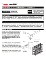
It is important to check your Local Government Authority requirements before the installation of your new Stratco Outback®
Flat Verandah. It is the builder’s responsibility to ensure any existing structure that an Outback Flat is being attached to is
adequately reinforced to accommodate the additional loads imposed by the verandah, patio or carport. Read these instructions
thoroughly before starting your project and refer to them constantly during each stage of construction. Contact Stratco for
advice if you do not have the necessary tools or information.
Before starting, lay out the main components in order of assembly on the ground and check them against the delivery note.
The ‘Components’ section identifies each part of your Outback Flat Verandah and shows the relative location of the
components.
Mark out the overall area of your verandah, patio or carport and ensure that it is free from obstructions. Beam to wall
connections can cause diculty if they coincide with door and window openings, so avoid these in your design. Ensure there
is reasonable access for materials and working space and consider the disposal of run-o water. Check the column and beam
positions on the ground; roughly check they are square by measuring the diagonals, then mark out the column locations. If
columns are to be ‘in ground’, dig the holes to Stratco specifications.
If required, search the Stratco YouTube channel for our range of installation videos for additional guidance.
TOOLS REQUIRED
• Drill and Hex-Head Adaptor
• Rivet Gun
• Tape Measure
• Tin Snips
• Spirit Level
• Hacksaw
• Post Hole Digger
• Silicone Gun
• Spanners or Ratchet
• Adjustable Construction Props
• Concrete
• Ladder
ADDITIONAL ITEMS
The components supplied do not include fixings to attach
the unit to an existing structure or concrete/masonry
anchors for the column installation. If required they must be
purchased as additional items.

STRATCO OUTBACK® FLAT ATTACHED INSTALLATION GUIDE
Back ChannelRoof Cladding
Gutter Stop Ends
Columns 150 Outback Beam120 Outback Beam Gutter
Beam Bracket Wall Bracket
Left Hand SHS
Connector
Inline SHS
Connector
Post Beam BracketRight Hand SHS
Connector
Downpipe Post CapDownpipe Outlet Beam End Cap
COMPONENTS
Suspension Bracket
68 Bolted Footing
Plate
SHS Footing Plate
Downpipe Bracket
150 In-Line Beam
Connector
PVC Nitrile
External & Internal
Gutter Mitres
Full Moment Beam
Connector
Beam Filler
Outback RoofliteTM
Universal Deck Strap
Notched Beam Filler

COMPONENT DIAGRAM
7
1
2
3
4
6
8
9
10
11
12
13
14
15
5
16
17
1. OUTBACK DECK
2. OUTBACK BEAM
3. POST CAP
4. POST BEAM BRACKET
5. OUTBACK EDGE GUTTER
6. 68 OUTBACK COLUMN
7. BACK CHANNEL
8. PVC NITRILE
9. WALL BRACKET
10. GUTTER END CAP
11. BEAM BRACKET
12. BEAM END CAP
13. GUTTER MITRE
14. DOWNPIPE OUTLET
15. BEAM FILLER
16. DOWNPIPE
17. DOWNPIPE BRACKET

BACK CHANNEL INSTALLATION
The short edge of the back channel is the underside. The back
channel should extend 50mm past the end of the beam to allow
for overflow into the gutter. If multiple lengths are required, butt
the channels together and waterproof with silicone.
Determine what type of fascia you are attaching your unit to
and what type of fixings and brackets you require (refer to
“Attaching to a Structure” section). Pre-drill the back channel
on the ground. Locate the first hole 100mm from the edge of
the back face of each length of channel. Drill the other holes
at 500mm centres for timber and brickwork or 250mm
centres for steel fascia. Run two beads of silicone along the
back of the back channel, with one near the top edge to
ensure a water tight seal.
FASCIA ATTACHMENT
When fixing the back channel to fascia the roofing above
each rafter must be removed to give adequate space
to install the fascia strengthening brackets. M10 Bolts
connect the fascia strengthening brackets to the rafter and
fascia (the number of brackets required is determined by
the builder, but the spacing should not exceed 1200mm).
Silicone as shown in the diagrams. When fixing to timber
fascia (Figure 1.0) attach the back channel using 12x25mm
hex head timber fixing screws through the pre-drilled
holes. When fixing to steel fascia (Figure 1.1) attach the
back channel using 12x20mm hex head self drilling screws
through the pre-drilled holes. The back channel is bolted
through the fascia to the fascia brackets with one M10 bolt
per bracket. Insert BIP foam into the back channel to act as a
weather seal when the roof sheets are pressed into it.
ATTACHING TO A BRICK WALL
When fixing the back channel to a brick wall, pre-drill the
anchor holes using a masonry drill bit. Attach the back
channel using M6x65mm masonry anchors through the
pre-drilled holes (Figure 1.2). Insert the BIP foam into the
back channel to act as a weather seal when the roof sheets
are pressed into it.
STEEL HOUSE FRAME ATTACHMENT
When fixing the back channel to the steel fascia on a
steel framed house, the roofing above each rafter must
be removed to allow enough room to install the rafter
strengthening brackets.
Attach angle brackets to 75x25x1.6mm RHS reinforcement
using 12x20 self drilling screws. Place the brackets above
the first web or truss connection at least 900mm from the
wall, and directly over the wall. Fasten with four 12x20 self
drilling screws to the chord or rafter (Figure 1.3).
Attach the extended fascia strengthening bracket to the
reinforcing RHS using 12x20 self drilling screws at 200mm
centres. It is the builder’s responsibility to determine the
adequacy of the fascia and rafters and the frequency of the
brackets for each individual situation (Figure 1.3).
For additional bracing, fix a tie down brace to the adjacent
studs. Use two 12x20 self drilling screws to fix the tie down
to the to chord, and on each stud use two 12x20 self drilling
screws on either side of the truss or rafter. Fix the back
channel to the fascia as previously mentioned.
STRATCO OUTBACK® FLAT ATTACHED INSTALLATION GUIDE
50 x 3mm Fascia Bracket
(bolt to Fascia and Rafters
with M10 Bolts)
12 x 25mm
Timber Fixing
Screws at max.
500mm centres.
Silicone seal behind
Back Channel
TIMBER FASCIA
Bitumen Impregnated
Foam insert or PVC Nitrile
FIGURE 1.0
STEEL FASCIA
Bitumen Impregnated
Foam insert or PVC Nitrile
Silicone seal behind
Back Channel
50 x 3mm Fascia Bracket
(bolt to Back Channel and
Rafter with M10 Bolts)
12 x 20mm Self Drilling
Screws at max. 250mm
centres to Fascia.
M10 Bolts
FIGURE 1.1
M6 x 65 Masonry Anchors
or
6mm diameter Screwbolts with a
minimum embedment of 45mm
Fix at max. 500mm centres
Silicone seal behind
Back Channel
BRICKWORK
Bitumen Impregnated
Foam insert or PVC Nitrile
FIGURE 1.2
Extended fascia
strengthening
bracket Angle
bracket
12x20
screws
60mm angle
bracket
Tie down
brace
Galvanised RHS
reinforcement Cross Section
Cross Section
FIGURE 1.3

ATTACHING TO A STRUCTURE
WALL ATTACHMENT
For units attached to a wall, position the wall brackets where
the beams meet the wall. The folded section on the tabs of
the bracket is located at the top. The highest point of the
wall bracket will be 15mm below the top beam. Mark the
holes and drill using an 8mm masonry bit. Fasten the bracket
to the wall with two M8 masonry anchors to a minimum
65mm embedment. The beam is slid into position and
fastened with four 12x20 self drilling screws (Figure 2.0).
SUSPENSION BRACKET ATTACHMENT
A suspension bracket is used when a beam is suspended
from the fascia. The top tab of the bracket must be located
under and over the back channel. Use silicone to seal
behind the suspension bracket and fascia. For steel fascia a
minimum of three 12x20 hex head screws are fixed through
the back channel, suspension bracket and fascia (Figure
2.1). For timber, three 12x25 type 17 screws are used to fix
through the back channel, suspension bracket and timber.
The rafter is slid into position and fastened using four 12x20
self drilling screws (Figure 2.1).
FLYOVER ATTACHMENT
Refer to the Outback Flyover Installation Guide document
for specific Flyover attachment details.
FRAMEWORK ERECTION
END FASCIA BEAM
When installing all beams, ensure the double thickness of
the beam is on top. Install the end fascia beam furthest from
the downpipe first. Lift the back channel end of the beam
up into the wall or suspension bracket while supporting
the other end on an adjustable construction prop. Adjust
the construction prop to allow for the required deck fall
minimum of one degree (or one and a half degrees for deck
spans over 4000mm). Fasten the end fascia beam to the
bracket using two 12x20 hex head screws either side in the
holes provided (Figure 3.0).
BRACKET AND FILLER CONNECTIONS
Measure the front fascia beam. Mark where the end fascia
beams, intermediate beams (if required) and columns meet.
Clip the post brackets onto the bottom of the front fascia beam
where the columns will sit. Fasten through the holes in the post
bracket with two 10x25 countersunk screws each side into the
flute of the beam (Figure 3.1).
Place the beam brackets on the inside face of the front fascia
beam, aligning their curved flange with the top groove of the
beam so that they clamp the beam fillers (notched beam filler
if over a post bracket) in place, fasten using two 12x20 self
drilling screws (Figure 3.2).
Two M8 masonry anchors,
or two 8mm diameter
screwbolts with a minimum
embedment of 65mm
Two 12 x 20
self-drilling
screws on
each side
15mm
Wall Bracket
FIGURE 2.0
Back Channel
Three 12 x 20mm
Self Drilling Screws
or
Three 12 x 25mm Timber
Fixing Screws (Timber
Fascia) through Back
Channel and Suspension
Bracket
Suspension Bracket
Rafter
FIGURE 2.1
End Rafter
Two 12x20 Self Drilling
Screws either side of the
Suspension Bracket
Construction Prop
Back Channel
Suspension Bracket
FIGURE 3.0
Post Bracket
Fasten with two
10x25 countersunk
screws per side
FIGURE 3.1
Beam Filler
Curved
Flange
Notched Beam Filler
Over Post Bracket
Beam Bracket
Clamps Over
Beam Filler
Two 12x20 hex
head screws
FIGURE 3.2

FASCIA BEAM TO RAFTER CONNECTION
Lift the front fascia beam and slide the rafter bracket onto
the end of the rafter beam so that the end of the rafter is
butted up against the back of the bracket. Support the front
fascia beam on construction props allowing for a 1 in 500
fall. Fasten the rafter beams either side with two 12x20 self
drilling screws (Figure 3.3).
IN-LINE BEAM CONNECTION
To butt join beams together an in-line beam connector is used.
The connector is placed so the join is in-line with the centre
of a column. On the ground, slide the connector into the end
of the beam. Fix using four 12x20 hex head screws either side.
Push the exposed half of the in-line connector into the other
beam until both beams meet flush and fasten as previously
described (Figure 3.4).
FULL MOMENT BEAM CONNECTION
If the beams must be joined at a location other than over
a post, a full moment beam connection is required (Figure
3.5). Slide the connector halfway inside the beam while it
is still on the ground. Fix the connector in place using six
12x20 self drilling screws; two either side of the beam and
two on top of the beam. Push the exposed half of the in-line
connector into the other beam until both beams meet flush
and fasten using six 12x20 self drilling screws.
INTERMEDIATE BEAMS AND PURLINS
I
ntermediate beams and purlins may be fitted at this stage
or following installation of the columns. Work progressively
from the first end of the unit. Locate the rafter brackets and
suspension brackets in the correct positions and fasten as
previously described. Lift the first intermediate rafter into
place and support on adjustable construction props (Figure
3.6). Secure all connections using two 12x20 hex head screws
either side of each bracket. Continue this process along the
Outback unit until the final end rafter beam is fixed in place.
FRAMEWORK CHECK
Check that the basic framework is square by ensuring the
diagonal measurements are the same. Recheck the falls are
correct for the roof and gutter (Figure 3.7).
STRATCO OUTBACK® FLAT ATTACHED INSTALLATION GUIDE
First end fascia beam
Front fascia beam
Intermediate beam
Wall bracket or
suspension bracket
Adjustable
construction
props
Purlin
FIGURE 3.6
Two 12x20 hex head
screws either side
Beam bracket fits inside
incoming beam
Front Fascia Beam
End Fascia Beam
FIGURE 3.3
In-line beam
connector
12x20 hex head
screws
Centre of column is
in line with join.
FIGURE 3.4
12x20 Self drilling
screws through the top
12x20 Self drilling
screws (either side)
38x25x1.6 RHS
welded to SHS
65x2.5 SHS
FIGURE 3.5
FIGURE 3.7
A
BA
B
Diagonal measurement
Fall
Fall
Fall toward the
downpipe position
Adjustable
construction prop

COLUMNS AND FOOTINGS
INTO CONCRETE
If fixing the columns into the ground, dig the holes to
the specified size. Place a half brick in the bottom of
the hole (Figure 4.0).
Measure from the underside of the beam to the top of the
half brick and cut posts to this length at each post location.
Use construction props or bracing to hold columns in
position, but do not concrete in place at this stage.
FOOTING ONTO CONCRETE
Footing brackets are available if the posts are to be fixed
to an existing concrete slab. Establish the column lengths
by measuring the distance from the underside of the fascia
beam to the concrete slab, less the thickness of the footing
plate (or 20mm for Outback footing plate).
68 OUTBACK FOOTING PLATE
For non-reinforced 68 Outback posts, cut the columns to
length, and assemble the footing bracket by sliding the legs
of the footing upstand through the slots in the footing plate
(Figure 5.0). The upstand bracing must be located between
the legs of the upstand.
Slide the assembled footing bracket and bracing into the
bottom of the column, and fasten with two 12x20 hex head
screws either side ensuring the top screws are located at
least 15mm from the top of the upstand with screws being a
minimum 30mm apart (Figure 5.0).
Slide the top of the column over the post bracket and align
the column and footing bracket. (Note: It may be necessary
to lift the fascia beam slightly to slide the column over the
post bracket). The unfluted faces of the column should be
aligned with each face of the post to beam bracket. Fasten
using two 12x20 hex head screws either side (Figure __).
Use construction props or bracing to hold columns in
position but do not bolt to the concrete slab at this stage.
SHS COLUMN FOOTING PLATE
Slide the SHS column footing bracket into the bottom of the
column, and fasten with two M10 bolts through the post
(Figure 5.1).
Screw the corner connector or inline connector to the top
of the SHS post with two 12x20 hex head self drilling screws
on either side of the column (Figure 4.2). Stand the post in
position and screw the connector to the outside face of the
beam with 12x20 self drilling hex head screws (Figure 5.1).
Use construction props or bracing to hold columns in
position, but do not bolt to the concrete slab at this stage.
FIGURE 4.0
Column embedded
minimum 450mm
into concrete
Half Brick
Depth as
specified
Width as
specified
Two 12x20 hex head
screws either side
Footing plate
Footing upstand
Upstand bracing
30mm (minimum)
FIGURE 5.0
Two M10 bolts
Minimum edge
distance
Minimum edge
distance
FIGURE 5.1

DECKING
TURNING THE DECKING ENDS
While still at ground level the ends of the decking need to be
turned up or down approximately 30 degrees using a turn
up/down tool to aid in weather proofing. Turn the ends of
the decking up at the back channel end and down at the
gutter end (Figure 6.0).
LAYING AND INSTALLING THE DECKING
Decking should have a 50mm overhang into the gutter and is
laid with the overlapping rib facing away from the prevailing
wind (Figure 6.1). Ensure all of the sheets have locking ribs
on the same side. Mark the back channel and front fascia
beam every 1000mm to check the decking is laid square.
Lift the first sheet into place and push it firmly into the BIP
foam in the back channel to weather proof it. Check the
sheet is square against the back channel and side fascia
beam. At the back channel end, rivet the decking from
underneath through the raised edge on the bottom of the
back channel with two 3.2mm rivets per pan (Figure 6.2).
Seal the rivets with silicone. At each supporting beam, fix
the sheet with two 12x20 hex head self-drilling screws per
pan (Figure 6.2) (In cyclonic conditions use three 12x20 hex
head self drilling screws per pan on supporting beams and
three rivets per pan at the back channel). Remove any swarf.
ATTACH COLUMN TO POST BRACKET
Slide the top of the column over the post bracket and align
the column and footing bracket if applicable. It may be
necessary to lift the fascia beam to slide the column over the
post bracket. The un-fluted faces of the column should be
aligned with each face of the post to beam bracket. Fasten
with two 12x20 hex head screws either side (Figure 5.2). Post
caps are used to cover the screw heads, press firmly into
position, silicone can be used to provide a better fixing.
SQUARE HOLLOW SECTION (SHS) COLUMNS
If 65x65mm or 75x75mm square hollow sections (SHS) have
been supplied, an alternative post to beam connection
method is used.
Measure from the underside of the beam to the top of the
half brick and cut posts to this length. Screw the corner
connector or inline connector to the top of the SHS post
with two 12x20 hex head self drilling screws on either side
of the column (Figure 5.3).
Stand the post in position. Screw the connector to the
outside face of the Outback beam with 12x20 self drilling
hex head screws (Figure 5.3).
Use construction props or bracing to hold columns in
position but do not fix in place at this stage.
STRATCO OUTBACK® FLAT ATTACHED INSTALLATION GUIDE
LAYING DIRECTION PREVAILING WIND
FIGURE 6.1
Turn Deck Down
(Gutter End)
Turn Deck Up
(Back Channel End)
FIGURE 6.0
Post cap
Post bracket Beam bracket
Notched beam filler
12x20 Self
drilling screws
10x25 Counter sunk
self drilling screws
FIGURE 5.2
SHS post
SHS corner
connector
SHS inline
connector
Beam to Beam
bracket
12x20
self drilling
screws
12x20
self drilling
screws
FIGURE 5.3

Lay the next sheet of decking over the previous sheet’s side
lap (Figure 6.1). At the back channel end press down on the
lap until the sheets clip together, continue working along the
length of the sheet using a timber block (to avoid damaging
the sheet) and rubber mallet. Finish by sliding the roof sheet
firmly into the BIP foam on the back channel. For larger
spans you may need to temporarily support the underside of
the roof sheeting while clipping the laps together. Continue
this process until all the roof decking is installed.
DECKING PARALLEL TO BACK CHANNEL
If the decking runs parallel to the back channel, slide the first
roof sheet sideways into the BIP foam in the back channel
for a weather proof seal. The sheeting is secured to the
back channel with rivets at 200mm centres (150mm centres
for cyclonic conditions), and it is secured to the beams
running parallel with the decking using hex head screws at
500mm centres. The roof sheets are fixed as standard to the
supporting beams (Figure 6.2).
OUTBACK ROOFLITETM INSTALLATION
An Outback Rooflite can be used to add natural light. The
polycarbonate Rooflite overlaps the deck by snapping or
sliding over the already installed sheets that have been
spaced 250mm apart. Note: the profile of the Rooflite is
dierent on each side, and therefore must align with the
correct connection on the deck (Figure 7.0).
Ensure the lower tab of the Rooflite touches the Outback
deck at the points shown (Figure 7.0) and all sheeting is
pushed firmly into the back channel. 9mm holes must
be pre-drilled through the Rooflite at all of the fastener
locations prior to fixing to allow for thermal expansion. The
Rooflite is fastened using 12x20mm hex head self-drilling
screws with domed washers at maximum 2000mm centres.
Fix through the groove located along the top of the Rooflite
connectors (Figure 7.1).
To finish the exposed end of the Rooflite an infill is required.
Fasten the infill over the Rooflite with 12x20mm screws and
domed washers on both sides through the pre-drilled holes.
Connect the infill to the underside of the decking with 3mm
rivets, seal the rivets with silicone. Finally, a foam insert is
placed into the back channel end of the Rooflite.
Back Channel
3.8mm Rivet through
Back Channel
Decking
FIGURE 6.2
FIGURE 6.3
12x20 Hex Head Screws
3.8mm Rivets
FRONT FASCIA BEAM SCREW LOCATIONS
BACK CHANNEL RIVET LOCATIONS
250mm
Outback Deck
Dip in the
profile
No dip in
the profile
Outback Deck
Note: each side of the profile is different, and
fits with the corresponding edge on the deck
FIGURE 7.0
Back Channel
12x20mm Hex Head Self Drilling
Screws with Domed Washers
Outback Deck
Outback Deck
Outback Rooflite
Rooflite Infill
Foam Insert
3mm Rivets
FIGURE 7.1

GUTTER ASSEMBLY
GUTTER PREPARATION
To establish the inside gutter length ‘A’ (Figure 8.0), measure
from the back of the back channel to the outside of the front
fascia and subtract 5mm for the mitre bracket. To establish
the inside gutter length for units with a deck overhang,
subtract 55mm from the total roof sheet length. To establish
inside gutter length ‘B’ for the front gutter, measure the
length of the front fascia beam and subtract 5mm for each
mitre bracket.
Attach the stop ends to the side gutters with four rivets per
stop end (Figure 9.0). Remove any swarf and waterproof
with silicone.
On the gutter ends that will form a corner, using the
template provided at the back of this book, mark out and cut
a 45 degree mitre (Figure 9.1). Fit the mitre brackets using
3.2mm sealed rivets to fasten the mitre to the gutter, then
waterproof with silicone.
GUTTER OUTLET ASSEMBLY
Before attaching the gutter mark the position of the outlet.
Place the downpipe in line with the column and mark and
cut a 75mm diameter hole in the base of the gutter near
the back edge. Insert the downpipe outlet from the inside
of the gutter and waterproof with silicone (Figure 9.2).
CAPPING
BEAM CAPS
To prevent moisture from entering the beams and for
aesthetics, any beams with exposed ends require end caps
to be fitted. Align the end cap and push into the exposed
beam end (Figure 8.0).
POST CAPS
If Outback columns are used, the post caps can be fitted
over the post-beam connection. Apply a small amount of
silicone to back of post cap, align the two lugs with the two
exposed holes of the post bracket and push firmly (Figure 8.1)
BEAM FILLERS
If a downpipe is to run flush with a column, place a notched
beam filler over the exposed post bracket and use silicone
to hold it in place (Figure 8.2).
STRATCO OUTBACK® FLAT ATTACHED INSTALLATION GUIDE
Beam end cap
FIGURE 8.0
Post cap (silicone
into bracket)
Post bracket
68 Outback column
FIGURE 8.1
Gutter
Notched
beam filler
Downpipe
FIGURE 8.2
159mm
159mm
A
B
Side Gutter
Front Gutter
External Corner Mitre
FIGURE 9.1
3.2mm Rivets
Waterproof with silicone
Gutter Stop End
FIGURE 9.0
75mm hole
Downpipe outlet
Silicone
FIGURE 9.2

FIRST SIDE GUTTER ASSEMBLY
After fixing a gutter mitre bracket to the corner of the first
side gutter, lift the gutter into place so the stop end slides
up behind the back channel. Use rivets to fasten the gutter’s
back lip to the roofing at the maximum spacing of one metre
(Figure 9.3). Waterproof the rivets with silicone. Ensure the
front face of the gutter remains vertical and even.
FRONT GUTTER ASSEMBLY
On the front gutter, attach a gutter mitre to the end opposite
the side gutter. Slide the flat end of the gutter straps inside
the rib of the roof sheets every metre. Hang the front gutter
on the gutter straps and using a rolling action, lift the back
of the gutter into the corner mitre of the side gutter. Check
the roof sheets overhang into the gutter by 50mm and the
gutters are square in relation to the framework. Fix the front
gutter with rivets at one metre spacings through the end
of the roof sheets into the gutter’s back lip. For units with
a deck overhang, fix the gutter to the roof sheets with two
rivets per pan. Rivet and seal the front gutter to the mitre and
the gutter straps to the roof sheets. Lift the final side gutter
so that its front end slides into the mitre and the stop end
slides up behind the back channel. Fix the gutter in position
as previously described and waterproof with silicone.
DOWNPIPES
Before attaching the downpipes, rivet the downpipe brackets
to the column. Slide the downpipe over the downpipe outlet
and rivet into position. Rivet the downpipe to the brackets.
Weatherproof all the fasteners with silicone.
FINAL FIXING
FIXING INTO THE CONCRETE FOOTING
Thoroughly check the posts with a spirit level. When plumb,
fill the post hole with approximately 150mm of concrete and
use a shovel or pole to agitate the concrete to remove any air
pockets. Repeat this process until the hole is full, continually
checking the posts as you go. The concrete must have a
slight slope that runs away from the column to ensure any
water does not pool around the base (Figure 10.0). Once the
concrete is set remove any temporary bracing or props.
FIXING ONTO EXISTING CONCRETE
68 OUTBACK COLUMN
If the 68 Outback Columns are to be fixed to an existing
concrete slab with a footing plate, each plate must be fixed
to the concrete with two M12x75 masonry anchors or two
M12x75 screwbolts (Figure 10.1).
Max. 1 Metre
spacing
Rivet
Gutter Strap
Side Gutter
Front Gutter
FIGURE 9.3
Concrete slopes
away from column
FIGURE 10.0
Two 12x20 hex head
screws either side
30mm (minimum)
Two M12x75 masonry
anchors or screw bolts
FIGURE 10.1

« SCAN THIS QR CODE TO FIND A STRATCO NEAR YOU
1300 155 155
stratco.com.au
All brands and logos/images accompanied by ® or ™ are trade marks of Stratco (Australia) Pty Limited. ® Copyright November 2021
STRATCO OUTBACK® FLAT ATTACHED INSTALLATION GUIDE
MAINTENANCE
Regular maintenance is essential to maintain the good
looks of all Stratco steel products and to ensure you
receive the maximum lifespan possible. Washing with
clean water must be frequent enough to prevent the
accumulation of dust, salts, and pollutants that may
reduce the life of the product. Stratco steel products
that are regularly washed by rain require no additional
maintenance. No Stratco steel structure or materials
are recommended for use over, or in close proximity, to
swimming pools or spas. No material that retains water
(such as dirt or paving sand) should be placed against
the columns. Care must be taken when determining
the location of Stratco steel products so that they are
not placed in close contact with sources of pollution
or environmental factors that could aect the life of
the steel. Refer to the ‘Selection, Use and Maintenance’
brochure for more information.
SHS COLUMN
If using SHS columns, the footing plate is to be fixed to
the concrete slab with four M12x75 masonry anchors or
screw bolts (Figure 10.2).
SHS REINFORCED OUTBACK COLUMN
Reinforced Outback Columns are to be fixed to the
concrete slab with four M12x75mm masonry anchors or
screw bolts (Figure 10.3).
Note: Anchors to be installed in accordance with
manufacturer’s specifications with appropriate concrete
edge distance as per manufacturer’s requirements.
IMPORTANT NOTE
Do not allow soil to remain in permanent contact with the
columns as corrosion will result in the base of the column. Refer
to the ‘Selection, Use and Maintenance of Stratco Steel Products’
brochure for complete details of the maintenance requirements.
Two M10 bolts
Minimum edge
distance
Four M12 chemical
anchors or equivalent
Minimum edge
distance
FIGURE 10.2
Two 12x20mm hex head screws
through both sides of column
SHS footing plate fixed to slab using
four M10 masonry anchors
FIGURE 10.3

STRATCO OUTBACK® FLAT ATTACHED INSTALLATION GUIDE
GUTTER FRONT
45° 45°
45°
55°
35°
135°
190°
0mm 50 60 70 80 9040302010 100mm
FOLD
FOLD
FOLD
FOLD
FOLD
FOLD
20mm 58mm 80mm
110mm 24mm
EDGE 160 EXTERNAL MITRE FLAT PATTERN TEMPLATE
CUTOUT TEMPLATE FOR MARKINGUP GUTTERS
FLIP TEMPLATE FOR LEFT & RIGHT VARIATIONS
ENSURE TEMPLATES ARE PRINTED AT “ACTUAL SIZE”
EXTERNAL PAGE 1

GUTTER FRONT
45° 45°
45°
55°
35°
135°
190°
0mm 50 60 70 80 9040302010 100mm
FOLD
FOLD
FOLD
FOLD
FOLD
FOLD
20mm 58mm 80mm
110mm 24mm
EXTERNAL PAGE 2

STRATCO OUTBACK® FLAT ATTACHED INSTALLATION GUIDE
GUTTER FRONT
45°
45°
170°
125°
45°
55°
45°
45°
0mm 50 60 70 80 9040302010 100mm
FOLD
FOLD
FOLD
FOLD
FOLD
FOLD
20mm 58mm 80mm
110mm 24mm
INTERNAL PAGE 1

EDGE 160 INTERNAL MITRE FLAT PATTERN TEMPLATE
CUTOUT TEMPLATE FOR MARKINGUP GUTTERS
FLIP TEMPLATE FOR LEFT & RIGHT VARIATIONS
ENSURE TEMPLATES ARE PRINTED AT “ACTUAL SIZE”
GUTTER FRONT
45°
45°
170°
125°
45°
55°
45°
45°
0mm 50 60 70 80 9040302010 100mm
FOLD
FOLD
FOLD
FOLD
FOLD
FOLD
20mm 58mm 80mm
110mm 24mm
INTERNAL PAGE 2

STRATCO OUTBACK® FLAT ATTACHED INSTALLATION GUIDE
GUTTER FRONT
0mm 50 60 70 80 9040302010 100mm
FOLD
FOLD
FOLD
FOLD
FOLD
FOLD
20mm 58mm 80mm
110mm 24mm
EDGE 160 135° EXTERNAL MITRE FLAT PATTERN TEMPLATE (A)
CUTOUT TEMPLATE FOR MARKINGUP GUTTERS
FLIP TEMPLATE FOR LEFT & RIGHT VARIATIONS
ENSURE TEMPLATES ARE PRINTED AT “ACTUAL SIZE”
PAIR BELOW TEMPLATE 135° EXTERNAL A WITH 135° EXTERNAL B SEE OVER
135° EXTERNAL PAGE 1

GUTTER FRONT
0mm 50 60 70 80 9040302010 100mm
FOLD
FOLD
FOLD
FOLD
FOLD
FOLD
20mm 58mm 80mm
110mm 24mm
135° EXTERNAL PAGE 2
135° INTERNAL MITRE
*TAGS FEATURED ON ONE SIDE OF EACH JOIN
135° EXTERNAL MITRE
135°
135°

STRATCO OUTBACK® FLAT ATTACHED INSTALLATION GUIDE
GUTTER FRONT
0mm 50 60 70 80 9040302010 100mm
FOLD
FOLD
FOLD
FOLD
FOLD
FOLD
20mm58mm
80mm
110mm24mm
135° EXTERNAL TAGS PAGE 1
EDGE 160 135° EXTERNAL MITRE FLAT PATTERN TEMPLATE (B)
(WITH TAGS)
CUTOUT TEMPLATE FOR MARKINGUP GUTTERS
FLIP TEMPLATE FOR LEFT & RIGHT VARIATIONS
ENSURE TEMPLATES ARE PRINTED AT “ACTUAL SIZE”
PAIR BELOW TEMPLATE 135° EXTERNAL B WITH 135° EXTERNAL A
FOLD TAGS TO FEED INSIDE ADJOINING GUTTER
RIVET MITRE SIDE A TO THE INTERNAL TAGS OF MITRE SIDE B ONCE NEATLY JOINED

GUTTER FRONT
0mm 50 60 70 80 9040302010 100mm
FOLD
FOLD
FOLD
FOLD
FOLD
FOLD
20mm58mm
80mm
110mm24mm
135°EXTERNAL TAGS PAGE 2
135° INTERNAL MITRE
*TAGS FEATURED ON ONE SIDE OF EACH JOIN
135° EXTERNAL MITRE
135°
135°
/