Extron DVS 304 User manual

Category
Recording Equipment
Type
User manual

This manual is also suitable for

The Extron DVS 304 Series of video and RGB digital scalers incorporate advanced technology
to provide high performance video processing with selectable output rates up to 1920x1200
(DVI models only) and HDTV 1080p, as well as simultaneous DVI (DVI models only) and
analog RGB or component video outputs.
This setup guide allows quick and easy set up and conguration of a DVS scaler using step by step instructions. It covers
performing basic operations using the front panel controls and selected Simple Instruction Set (SIS
) commands.
N
For full installation, configuration, and operation details, refer to the DVS 304 Series User’s Manual, online at www.extron.com.
Installation — Rear Panel Features (DVS 304 DVI AD model shown)
INPUTS OUTPUT
RS-232
LAN
RESET
ACTLINK
50/60 Hz
100-240V .3A
2
1
3
4
LR
LR
LR
LR
LR
AUDIO
VID
1
2
3
4
Y
/VID
R-Y
H/
HV
R
/R-Y
V
G
/Y
B
/B-Y
DVI-I
YC
SDI
B-Y
/C
RGB/R-Y, Y, B-Y/YC/VID
I
N
P
U
T
O
U
T
P
U
T
6
3a
3
7
4
5
9
1
2
11
8
10
DVS 304 DVI AD
Power and video input connections Output and control connections
a AC power connector g Audio output connectors - (audio models only)
b Audio input captive screw connectors (inputs 1 to 4) - audio models only h RGB/YUV-HD BNC and DVI* output connectors
c Composite video BNC connector (input 1) i Reset button and LED
Ñ (Optional) SDI BNC connectors (congurable) j RJ-45 Ethernet connector
d Composite video/S-video/component video BNC connectors (input 2) k 9-pin D RS-232 connector
e S-video 4-pin mini-DIN connector (input 3)
f 15-pin HD connector (input 4) with EDID emulation*
Installation and cabling
Step 1 — Mount the DVS
Turn off or disconnect all equipment power sources and rack mount the DVS unit, using
suitable mounting brackets or rack shelf (see image at right).
Refer to the DVS 304 Series Users Manual for details.
Step 2 — Connect inputs
Connect inputs from video and/or audio sources to the applicable connectors marked
“Inputs” (see b to f above for connector types). See diagrams below for signal format on BNC
connectors and audio input captive screw wiring (balanced or unbalanced, mono or stereo).
N When connecting a VGA input to a DV 304 DVI model, by default the EDID emulation is set to match the current output rate. To set to a specific rate,
or set to a display's EDID rate, or to upload a custom EDID table refer to the DVS 304 Series User’s Manual, available at www.extron.com.
Component video
(Y, R-Y, B-Y)
S-video
Composite video
B-Y
/C
Y
/VID
R-Y
B-Y
/C
Y
/VID
R-Y
B-Y
/C
Y
/VID
R-Y
Input 2
Input 4
Pin 1
15-HD pins Pin 2
Pin 3
Pin 13 Pin 14
Input source
BNC’s
R
V
H
B
G
RGB
RGBcvS
YUV
S-video
Composite video
R
G(S)
B
HV
R
G
B
cvS
R-Y
Y
B-Y
Y
C
Y
DVS 304 Series – Setup Guide
Rack Mount
Bracket
Unbalanced Stereo Input
Tip
Sleeve
Sleeve
Tip
L R
Unbalanced Mono Input
Balanced Mono Input
L R
Tip
Ring
Sleeve
Tip
Ring
L R
Tip
Sleeve
Tip
Sleeve
Balanced Stereo Input
L R
Tip
Ring
Sleeve
Tip
Ring
Do not tin the wires!
N * DVI models only. Non DVI models have a 15-pin HD connector
in place of the DVI connector and do not feature EDID emulation.
68-1039-50
Rev. A
08 09
DVS 304 Series • Setup Guide
2
DVS 304 Series — Setup Guide (cont'd)
Step 3 — Connect outputs
Connect video and audio output devices to the applicable connectors marked “Outputs” (see g and h above).
Video For RGB (RGBHV, RGBS, RGsB) or HD component (R-Y, Y, B-Y) video output connect cables to the BNC's or VGA/DVI-I as shown
below. Outputs are scaled or pass-through RGB ,or scaled component video and can be scaled to more than 60 different output rates.
N
RGB pass-through is available on analog outputs only. DVI output is disabled in RGB pass-through mode.
RGBHV
H/
HV
R
/R-Y
V
G
/Y
B
/B-Y
R
/R-Y
G
/Y
B
/B-Y
RGsB
H/
HV
V
R
/R-Y
V
G
/Y
RGBS
H/
HV
B
/B-Y
B
/B-Y
Component video (Y, R-Y, B-Y)
R
/R-Y
G
/Y
H/
HV
V
Analog video output
For DVI-I (digital and analog) output (DVS 304 DVI models only), connect a suitable display device
to this DVI-I connector for scaled RGB or component video (simultaneous digital and analog outputs).
AudioWire the captive screw audio connectors as shown above.
Step 4 — Connect control devices
LAN Ethernet port
j
Connect to an Ethernet LAN or WAN via this RJ-45 connector to control the switcher from a remote
location using a PC’s Internet browser, or the control program (the Extron Signal Processing Products Control Program).
The Ethernet connection indicator LEDs indicate the status of the Ethernet connection: the green LED lights when connected to an
Ethernet LAN, and the amber LED ickers as the devices communicate.
N
Do not use standard telephone cables, as they do not support Ethernet or Fast Ethernet. Do not stretch or bend cables as transmission
errors could occur.
Remote port k For serial RS-232 control, connect a host computer or control system via this 9-pin D connector.
RS-232 protocol (default values): 9600 baud, 1 stop bit, no parity, 8 data bits, no ow control.
N
See chapter 4, “SIS
Programming and Control”, in the DVS 304 Series User’s Manual, for definitions of the SIS commands.
See chapter 5, “DVS 304 Series Control Software” to install and use the control software.
Use an RS-232 cable that only utilizes Tx (2), Rx (3), and ground (5) to avoid activating the contact closure feature (refer to the
DVS 304 Series User's Manual, chapter 2).
Step 5 — Connect power
AC power connector
a
Plug in a standard IEC power cord from a 100 to 240 VAC, 50 - 60 Hz power source into this receptacle
Powering Up
When applying power to the DVS, the unit undergoes a start-up self testing sequence (see image below), and then the LCD displays
the default display cycle, showing the active input, input signal type, and the output resolution and refresh rate.
2
sec.
5
sec.
Apply
Power
Extron
Electronics
1
sec.
2 sec.
2
sec.
Default Display Cycle
INPUT 4
RGB SCALED
OUTPUT
N
The input and output rates shown
in the default display cycle may differ,
depending on the active input and type of video signal
.
All input LEDs flash
once in sequence
(last active, then 1-4).
1
sec.
2
sec.
Last active input
LED remains lit
(here input 3).
= flashing
Key
1
3
60-xxxx-xx
FW ver. 2.00
= lit
DVS 304
DVI AD
2
sec.
N
When in use and not in any menu, the LCD screen defaults to cycling through the current input/output configuration. The displayed
content may vary, depending on the input video signal type (see typical default display above).
DVI-I
Unbalanced Stereo Output
L R
Balanced Stereo Output
Left
Right
CAUTION
For unbalanced audio, connect the sleeve(s) to the center contact
ground. DO NOT connect the sleeve(s) to the negative (-) contacts.
Tip
Sleeves
Tip
NO GROUND HERE
NO GROUND HERE
L R
Left
Right
Tip
Ring
Sleeves
Tip
Ring
Audio output
3
DVS 304 Series • Setup Guide
Front Panel Overview
a
Input selection buttons — Select/switch inputs and indicate which input is active (button LED lights green). A blinking LED
indicates an audio breakaway input (audio models only).
Button 1 selects input 1 - composite video.
Button 2 selects input 2 - composite video, S-video, or component video.
Button 3 selects input 3 - S-video.
Button 4 selects input 4 - RGB scaled (RGBHV, RGBS, RGsB), RGB pass-through, RGBcvS, YUVi, YUVp/HDTV, S-video or
composite video.
N
RGB pass-through mode (inputs pass at their native rate without additional processing) is available on analog outputs only. The DVI
output is disabled in RGB pass-through mode.
b
Menu button — This button allows navigation through the DVS's system menu (top level).
c
Next button — This button allows navigation through the submenus and to start selected functions, such as Auto-Image
.
d
LCD display — This 12x2 screen displays device status, settings, and menu conguration information.
e
Infrared (IR) sensor — This sensor is used to receive IR signals from the IR 902 remote control.
N For detailed information on the IR 902 remote, refer to the DVS 304 Series User's Manual, available online at www.extron.com.
f and g
Adjust knobs — These are used with the menu navigation buttons to adjust device settings and picture control.
Setting the front panel lock (Executive mode)
The DVS has a front panel security lock feature that limits the operation of the unit from the front panel.
Executive mode 0 (disabled) — The front panel is fully unlocked. This is the default setting.
Executive mode 1 (enabled) — The front panel is locked except for input switching.
Enabling or disabling Executive mode 1 from the front panel
Press and hold the Menu and Next buttons until the LCD display indicates the Executive mode is either enabled or disabled.
N
If the DVS is in Executive mode 0 (unlocked), this procedure selects mode 1 (locked).
If it is in Executive mode 1, this procedure selects mode 0 (unlocked).
When Executive mode is enabled and a front panel action is attempted (other than input switching), the LCD displays the status for
2 seconds. Executive mode 1 can also be enabled or disabled by SIS commands.
Configuring the DVS using the front panel system menus
The DVS has eight or nine front panel conguration menus:
Start Auto Image, Input Conguration, Picture Control, Output Conguration, Audio Conguration (only seen on audio models),
Memory Presets, IP Conguration, Advanced Conguration, and the Exit Menu
.
N
For detailed information on the menus, refer to the DVS 304 Series User's Manual, available online at www.extron.com.
To use a menu, press the Menu button to access the Main menu, then repeatedly press the Menu button to cycle through the list to
the desired menu. Press Next to enter the desired submenu, and follow the steps on page 4.
N Press Menu at any time to exit a submenu and return to the main menu.
Menu
Menu
Menu
Menu
Menu
Menu
START AUTO
IMAGE ON INx
INPUT
CONFIG
PICTURE
CONTROL
OUTPUT
CONFIG
AUDIO
CONFIG
MEMORY
PRESETS
IP
CONFIG
ADVANCED
CONFIG
TO EXIT MENU
PRESS NEXT
(Audio models only)
2 sec.
2
sec.
Default Display Cycle
INPUT 4
RGB PASS
OUTPUT
Menu
Menu
Menu
Menu
Next
DVS 304 Series — Setup Guide (cont'd)
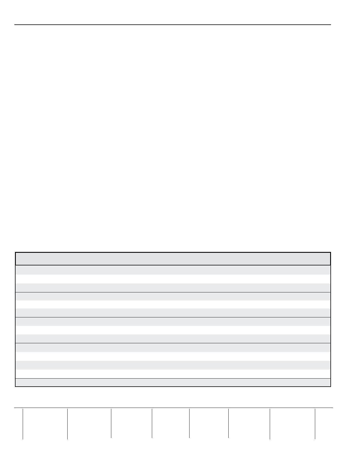
Commands ASCII command
(host to switcher)
Response
(switcher to host)
Additional description
Input selection — video and audio
X7!!
In X7!•All] Select video and audio from input source X7!.
Input selection — video
X7!&
In X7!•RGB] Select video from input source X7!.
Input selection — audio
X7!$ In X7!•Aud] Select audio from input source X7!
Video mute — enable 1B Vmt1] Blanks selected input.
Video mute — disable 0B Vmt0] Displays selected input.
Video mute — status B
X8) ]
View the blanking status (0= disabled, 1= enabled).
Audio mute — on (audio models only) 1Z Amt1] Mute selected input.
Audio mute — off 0Z Amt0] Un-mute selected input.
Audio mute — status Z
X8)]
View mute status (0= mute off, 1= mute on).
Set volume (audio models only)
X10$V Vol X10$ ] Set volume to X10$.
Increment volume +V
Vol
X10$ ]
Increase volume.
Decrement volume - V
Vol
X10$ ]
Decrease volume.
View volume setting V
X10$ ]
View current volume setting.
Start Auto-Image 55* 2# Img2] Initiate an Auto-Image on the selected input.
Extron USA - West
Headquarters
+800.633.9876
Inside USA / Canada Only
+1.714.491.1500
+1.714.491.1517 FAX
Extron USA - East
+800.633.9876
Inside USA / Canada Only
+1.919.863.1794
+1.919.863.1797 FAX
Extron Europe
+800.3987.6673
Inside Europe Only
+31.33.453.4040
+31.33.453.4050 FAX
Extron Asia
+800.7339.8766
Inside Asia Only
+65.6383.4400
+65.6383.4664 FAX
Extron Japan
+81.3.3511.7655
+81.3.3511.7656 FAX
Extron China
+400.883.1568
Inside China Only
+86.21.3760.1568
+86.21.3760.1566 FAX
Extron Middle East
+971.4.2991800
+971.4.2991880 FAX
© 2009 Extron Electronics. All rights reserved.
N
X7!
= Input number (1 – 4)
X8)
= Mode status 0 = disabled, off; 1 = enabled, on
X10$
= Volume level range = 000 to 100 (always returns 3 digits)
1. To start Auto-Image
on an input, press the Next button, then press it again to conrm. Auto-Image is a quick way to
size an input to t the current display window.
2. Within the Input Conguration menu press Next to cycle to the desired submenu. Rotate either Adjust knob ({ [) to
change input values (Input Type, Aspect Ratio, etc.,) as required.
3. Within the Picture Control menu press Next to cycle to the desired submenu. Rotate either Adjust knob to change
values (H or V Size/Position, Detail, etc.,).
4. Within the Output Conguration menu press Next to cycle to the desired submenu. Use either Adjust knob to
congure the output resolution and refresh rate, the output signal type, and the sync polarity.
5. For DVS models with audio, the Audio Conguration menu is available. Press Next to enter the submenu and use
either Adjust knob to raise or lower the input audio level (range is -15 to +9 dB) for the current input.
6. Within the Memory Presets menu press Next and use the Adjust knobs to select the preset to Save to or to Clear.
7. The IP conguration menu shows the current IP settings (IP Address, Subnet Mask, and Gateway Address).
To
change the settings, press and hold Next and Input 4 buttons simultaneously until the IP address's rst octet
blinks. Use both Adjust knobs to enter the address details. Press Next to save the changes and go to the next
submenu. Finally press Menu to exit and save.
8. Within the Advanced Conguration menu press Next to cycle to the desired submenu. Use either Adjust knob to
change the settings for Auto Image, Blue Mode, Auto Switch, RGB delay, OSD Label, Test Pattern, Enhance Mode,
Refresh Lock, and Auto Memory.
9. At the Exit menu press Next to exit to the default display cycle.
Configuring the DVS using the Signal Processing Products Control Program
1. Install the program from the supplied DVD (or from www.extron.com) onto a local PC connected via LAN to the DVS.
2. Open the program and at the main window click Help, Contents (or press F1) and follow the instructions.
Configuring the DVS using the internal Web page
The scaler can be congured with its internal Web page, accessible from a LAN connected PC.
1. Open a Web browser on the connected PC and at the address line type in the DVS device's IP address.
This opens the
DVS 304's internal Web page showing the current status and conguration.
2. To congure the DVS refer to the DVS 304 Series User’s Manual, available at www.extron.com.
Configuring the DVS using SIS commands
The scaler can be congured with specic SIS commands via RS-232 or a LAN connection. The table below lists a selection of the
commands. For a full list of SIS commands refer to the DVS 304 Series User’s Manual.
  • Page 1 1
  • Page 2 2
  • Page 3 3
  • Page 4 4

Extron DVS 304 User manual

Category
Recording Equipment
Type
User manual
This manual is also suitable for

Ask a question and I''ll find the answer in the document

Finding information in a document is now easier with AI