Page is loading ...

1
Macerator Toilet
Installation Manual . . . . . . . . . . . . . .4
EN
WC dilacérateur
Instructions de montage .......25
FR
WC con maceratore
Instrucciones de montaje.......47
IT
Zerhackertoilette
Montageanleitung ............14
DE
Inodoro triturador
Instrucciones de montaje.......36
ES
Versnijdingstoilet
Montagehandleiding ..........58
NL
MASTERFLUSH
MF 7100, MF 7200
MF 7200
MF 7100
Findelingstoilet
Monteringsvejledning. .........68
DA
Maceratortoalett
Monteringsanvisning ..........78
SV
Macerator-toalett
Monteringsanvisning ..........88
NO
Silppuripumppu-wc
Asennusohje . . . . . . . . . . . . . . . .98
FI
Sanita de trituração
Instruções de montagem ......108
PT
Darálós vécé
Szerelési útmutató...........160
HU
Унитаз с мацератором
Инструкция по монтажу ......119
RU
Toaleta z rozdrabniaczem
Instrukcja montażu ..........129
PL
Toaleta s maceračním
čerpadlem
Návod k montáži ............140
CS
Macerátorová toaleta
Návod na montáž ...........150
SK

2
1
2
3 4 5 6 7
3
Dometic MasterFlush
A
D
E
C
A
B
1
A
B
C
D
E
G
F
3 4
B1-B2

4
2.1 Warnings – marine applications
The following statements must be read and understood before installing, servicing and/or
operating this product on a boat. Modification of this product may result in property damage.
Dometic recommends that a qualied marine technician or electrician install or service this product.
Equipment damage, injury to personnel or death could result from improper installation. DOMETIC
ACCEPTS NO RESPONSIBILITY OR LIABILITY FOR DAMAGE TO EQUIPMENT, OR INJURY OR
DEATH TO PERSONNEL THAT MAY RESULT FROM IMPROPER INSTALLATION, SERVICE OR
OPERATION OF THIS PRODUCT.
Dometic MasterFlush Notes on using the manual
1 Notes on using the manual .................................................4
2 General safety instructions ..............................................4 – 5
3 Components ............................................................6
4 Specications ........................................................6 – 7
5 Installation ..........................................................8 – 13
6 Customer service........................................................13
1 Notes on using the manual
Note
Supplementary information for operating the device.
fig.
1
A, page 2 : This refers to an element in an illustration. In this example, item A in
gure 1 on page 2.
Caution!
Safety Instruction: Failure to observe this instruction can cause material damage and
impair the function of the device.
Caution! Hazard of Flooding
If the toilet is connected to ANY through-the-hull ttings, properly installed seacocks MUST
be installed in all piping connected to through-the-hull ttings. Seacocks MUST be easily
accessible to all users of the toilet or secondary valves tted in hoses where they are easily
accessible. All valves MUST be full bore valves and of marine quality. Screw-to-close gate
valves are not recommended. Failure to do so can result in ooding which can cause loss
of property and life.
EN
Table of contents
2 General safety instructions
The manufacturer will not be held liable for claims for damage resulting from the following:
• Faultyassemblyorconnection
• Damagetotheunitfrommechanicalinuences,misuseorabuse
• Alterationstotheunitwithoutexpresswrittenpermissionfromthemanufacturer
• Useforpurposesotherthanthosedescribedintheoperatingmanual
Make sure to follow any governing codes or standards that apply to your installation.

5
General safety instructions
Caution! Hazard of Flooding
If toilet uses sea water for ushing at ANY time, a sea water pump controlled by an auto-
matically operating demand switch MUST NOT be installed. If the onboard water valve or
any plumbing connections were to leak, the automatically operated pump would start and
could ood the boat. Failure to comply can cause loss of property and life.
Caution! Hazard of Flooding
Before beginning any work on this product, be sure that all electrical power to the unit has
been turned off and that seacocks are in the CLOSED or OFF position. Failure to do so can
result in ooding which can cause loss of property and life.
Caution!
Do not connect sea water ush toilet (models 7160, 7180) to an onboard potable water
system. Failure to comply could result in contamination of the potable water supply.
Caution! Hazard of Flooding
Do not connect sea water ush toilet (models 7160, 7260) to an onboard pressurized water
system. Failure to comply can result in ooding which can cause loss of property and life.
Caution! Hazard of Shock or Fire
Always use recommended fuse, circuit breaker and wire size. Failure to do so can result in
re that can cause the loss of property and life.
Caution!
Overlling the holding tank can create serious damage to the sanitation system, such
as rupturing the holding tank and releasing tank contents into the bilge. To prevent this
possibility, Dometic recommends using a “full” tank shut-down relay from the “full” signal
generated by an optional Dometic DTM01C tank monitor or DTM04 four-level tank monitor
system.
Caution! Hazard of Flooding
If toilet rim is ever less than 8 in. (20 cm) above the highest possible waterline at ANY time
(during any conditions of heel, load or trim) and is connected to ANY through-the-hull
ttings, properly positioned ventilated (vented) loops MUST be installed in intake* or dis-
charge piping to prevent potential back siphonage of sea water into the boat. Vented loops
must be equipped with integral check valve that permits air into line to prevent siphoning.
Failure to do so can result in ooding which can cause loss of property and life.
* if connected to sea water
Caution! Hazard of Flooding
If toilet is connected to ANY through-the-hull ttings, ALL exible hoses must be of marine
sanitation quality and must be secured to ANY ttings (such as those at seacock, vented
loop or toilet) with two stainless steel, worm-drive hose band clamps at each connection.
Connections MUST be checked frequently for integrity. Failure to comply can result in
ooding which can cause loss of property and life
.
Dometic MasterFlush

6
Components
Caution!
Discharge of sewage directly overboard is illegal in some areas. Please check all local laws
before operating an overboard discharge sanitation system.
3 Components
Carton contents (g.
1
)
Toilet components (g.
2
)
Ref. Description
A Macerator toilet
B1 DFS-2F ush switch (standard -
freshwater ush toilet)
B2 DFS-1F ush switch (standard -
sea water ush toilet)
C 1.5 in. (38 mm) discharge tting
D Floor mounting hardware kit
E Water supply hose kit
NS Parts list, installation and operation
instructions, quick-start guide
Ref. Description
1 Rim ush check valve (freshwater
toilet) or adapter (sea water model)
2 Water supply hose
3 Macerator pump
(under plastic cover)
4 Electric water valve
5 Product ID label location
6 Stainless steel compression band
7 Discharge tting
Refer to complete parts list (packed separately)
for additional information.
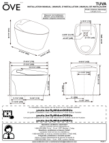
4 Specifications
4.1 Dimensions (g.
3
)
Ref. Dimension
A 13.25 in. / 337 mm
B 14.5 in. / 368 mm
C 18.75 in. / 476 mm
D 12.25 in. / 311 mm - seat height
E 13.75 in. / 349 mm
F 10 in. / 254 mm
G 26.25 in. / 667 mm - seat lid up
Ref. Dimension
A 14.75 in. / 375 mm
B 15 in. / 381 mm
C 19 in. / 483 mm
D 13.75 in. / 349 mm - seat height
E 13.75 in. / 349 mm
F 10 in. / 254 mm
G 28.75 in. / 730 mm - seat lid up
Toilet models 7220, 7260
(compact marine bowl)
Toilet models 7120, 7160
(standard bowl)
All dimensions may vary 0.375 in. (10 mm)
Dometic MasterFlush

7
Specifications
Dometic flush switch panel
(g.
4
)
Ref. Dimension
A 3.25 in. / 83 mm
B 1.625 in. / 41 mm
4.3 Minimum System Requirements
4.2 Materials
Toilet: vitreous ceramic
Toilet base: polypropylene
Dometic flush switch panel: polystyrene (DFS-1F or DFS-2F);
or powder-coated aluminum (DFST)
Electrical
Power draw 20 amps/12 V DC; 10 amps/24 V DC
Circuit breaker 25 amps/12 V DC; 15 amps/24 V DC
Wiring
12 ga. (up to 25 ft./7.6 m total circuit)
Consult ABYC guidelines for additional information.
Water
Supply
Fitting size
Supply hose ID
0.5 in. NPT – fresh water ush toilet
0.75 in./19 mm ID – sea water ush toilet
Flow rate 2.0 gpm/7.6 lpm minimum – fresh water ush
Discharge
Inside diameter 1.5 in./38 mm or 1 in./25 mm
Horizontal run* 40 ft./12.2 m maximum
Vertical run* 4 ft./1.2 m maximum
* Horizontal and vertical run distances are not cumulative. Check for adequate discharge ow
if installation nears one of these limits.
Specications are subject to change without notice.
Dometic MasterFlush

8
0.75 in./
19 mm
SEACOCK
1 in./ 25 mm
or 1.5 in./38 mm
SEACOCK
0.75 in./
19 mm
SEACOCK
1 in./ 25 mm
or 1.5 in./38 mm
SEACOCK
MAKE LOOP
12 in./305 mm
ABOVE FLOOR
MACERATOR
TOILET
Installation
5 Installation
5.1 Above water line system layouts
Note
Determine whether the water supply to the toilet will be fresh water or sea water, above or below the
vessel’s water line, and then follow the appropriate instructions for the installation.
5
6
VENT
FITTING
0.75 in./ 19 mm ID
SEA WATER LINE
0.75 in./ 19 mm ID
SEA WATER LINE
0.5 in./
13 mm ID
FRESH
WATER
LINE
0.5 in./
13 mm ID
FRESH
WATER
LINE
FROM
FRESH
WATER
SUPPLY
FROM
FRESH
WATER
SUPPLY
CHECK VALVE is needed
to ensure sea water pump
stays primed between uses
CHECK VALVE is needed
to ensure sea water pump
stays primed between uses
Add vented loop here
if holding tank is
below water line.*
1 in./ 25 mm
or 1.5 in./38 mm ID
SANITATION HOSE
VENT
FILTER
HOLDING TANK
(cut-away view)
DISCHARGE
PUMP
DECK
DISCHARGE
WATER LINE
WATER LINE
Toilet with direct overboard
discharge
Toilet with
holding tank
discharge
Caution! Hazard of Flooding
All vented loops should be installed a minimum of 8 in./20 cm above water line at full heel.
*
Dometic MasterFlush

9
HOLDING
TANK
(cut-away
view)
1 in./25 mm or
1.5 in./38 mm ID
SANITATION HOSE
0.75 in./
19 mm
SEACOCK
1 in./ 25 mm
or 1.5 in./38 mm
SEACOCK
FROM
FRESH WATER SUPPLY
FROM
FRESH WATER SUPPLY
0.75 in./
19 mm
SEACOCK
1 in./ 25 mm
or 1.5 in./38 mm
SEACOCK
MACERATOR
TOILET
MACERATOR
TOILET
Installation
5.2 Below water line system layouts
7
8
VENT
FITTING
0.75 in./ 19 mm ID
SEA WATER LINE
0.75 in./ 19 mm ID
SEA WATER LINE
0.75 in./ 19 mm ID
VENTED LOOP *
0.75 in./ 19 mm ID
VENTED LOOP *
0.5 in./ 13 mm ID
FRESH WATER LINE
0.5 in./ 13 mm ID
FRESH WATER LINE
Add vented loop here
if holding tank is
below water line.*
1 in./25 mm or
1.5 in./38 mm ID
VENTED LOOP *
1 in./25 mm or
1.5 in./38 mm ID
VENTED LOOP *
VENT
FILTER
DISCHARGE
PUMP
DECK
DISCHARGE
Toilet with direct overboard
discharge
Toilet with
holding tank
discharge
Caution! Hazard of Flooding
All vented loops should be installed a minimum of 8 in./20 cm above water line at full heel.
*
1 in./ 25 mm
or 1.5 in./38 mm ID
SANITATION HOSE
WATER LINE
WATER LINE
Dometic MasterFlush

10
5.3 Inlet plumbing requirements
For sea water flush models:
1. Seacock and inlet water line (not supplied with toilet):
a. 3/4 in. (19 mm) full-ow seacock and 3/4 in. (19 mm) ID exible hose. Follow seacock
manufacturer’s installation instructions.
b. Make sure inlet seacock is below sea water line at all times, during all conditions of full heel.
c. Make sure all inlet hose connections have no sharp bends or restrictions.
d. Use two stainless steel hose clamps at each connection.
e. Provide hose support every 3 ft. (0.9 m) along inlet hose run to limit movement.
f. Keep hose runs as short as possible. Eliminate sags or low spots that may hinder ow.
2. Water inlet strainer (not supplied with toilet)
a. 100-mesh strainer is recommended between inlet seacock and sea water ush toilet.
3. Inlet check valve for above-waterline installations (not supplied with toilet):
a. A check valve should be installed in inlet supply line to assure toilet’s sea water pump stays
primed between ushes.
b. Check valve should be located as close as possible to the inlet seacock (
5
,
6
).
4. Vented loop (not supplied with toilet):
a. If the toilet rim will ever be less than 8 in. (20 cm) above the highest possible waterline at any
point of heel, trim or load, then a 3/4 in. (19 mm) vented loop must be installed in the inlet
hose between the inlet seacock and the toilet (
7
,
8
).
b. Vented loop must be positioned a minimum of 8 in. (20 cm) above highest possible waterline
during all conditions of heel, trim or load.
Warning!
Do not connect sea water flush toilet inlet line to a pressurized freshwater system.
This will result in a continuously running freshwater pump, which can possibly overow
the toilet bowl, ood the boat, and cause potential loss of property or life.
Warning!
Do not connect sea water flush toilet inlet line to an onboard potable water system
in any way. This can cause contamination of the potable water system. If fresh water
is desired, purchase the freshwater-ush version of the toilet, or provide a separate
freshwater tank that supplies water only to the toilet.
For freshwater flush models:
1. Inlet water line (not supplied with toilet):
a. 0.5 in. (13 mm) ID exible hose with 1/2 in. NPT tting connects to toilet water valve.
2. Shut-off valve in inlet line (not supplied with toilet):
a. For toilet cleaning and maintenance.
InstallationDometic MasterFlush

11
Installation
5.4 Outlet plumbing requirements
For sea water flush models:
1. Seacock and outlet sanitation hose (not supplied):
a. 1 in. (25 mm) or 1.5 in. (38 mm) full-ow seacock and exible
hose to route waste to a holding tank with discharge pump,
or route directly overboard. Follow seacock manufacturer’s
instructions.
b. Make sure waste outlet seacock is both aft and higher than
the water inlet seacock.
c Outlet plumbing should have no sharp bends or restrictions.
d. Use two stainless steel hose clamps at each connection.
e. Provide support along entire hose run to limit movement and
side-loading on connections.
f. Keep hose runs as short as possible. Eliminate sags or low
spots that may hinder ow.
2. Discharge hose loop near toilet (not supplied with toilet):
a. To retain water in toilet bowl, make a 12 in. (30 cm) high loop
in discharge line as near to toilet as possible
(gs.
5
,
6
).
3. Vented loop (not supplied with toilet):
a. Refer to toilet system layout gures
6
and
7
–
8
for
recommended locations of discharge vented loops connect-
ed to system components that are below the water line or
may be less than 8 in. (20 cm) above highest possible water
line at full heel.
b. Vented loops must be positioned a minimum of 8 in. (20 cm)
above highest possible water line at full heel.
5.5 Toilet and flush switch installation
1. Carefully unpack toilet, water supply hose, discharge tting
and hardware (g.
1
).
2. Place toilet in desired location on oor. If necessary, rotate
toilet so that macerator pump housing (g.
2
3) does not
interfere with walls, or so that it will better accommodate the
intended plumbing layout. Conrm adequate clearance is
available for plumbing connections, and also the seat and lid
in raised position. Mark oor where toilet will be installed.
3. (Optional) If macerator pump and base must be positioned at
an angle so that toilet bowl does not face in correct direction,
the upper bowl can be rotated to the proper position:
a. Loosen compression band (
9
) just enough to slip down
past lower plastic clamp, and remove upper and lower
plastic clamps (
10
).
b. Lift bowl. Make sure notch in black rubber gasket sits around shallow pin on toilet base and
remains centered between bowl and base (
11
). Rotate bowl to desired position, then set it
down on gasket.
c. Re-position plastic clamps and compression band between upper bowl and base. Join
clamps together at front of toilet bowl (there will be a space between the clamps behind the
bowl). With compression band screw positioned on a clamp (not in gap between clamps)
(
9
), tighten compression band to 65 in.-lbs.
9
12
13
10
11
Dometic MasterFlush

12
Installation
4. Connect water supply hose between check valve or adapter
(g.
2
1) and water valve (freshwater ush model) or water
pump (sea water ush model) on base.
a. Cut supply hose to length that will not kink when connected.
b. Remove plastic cover (g.
2
3) from pump.
c. With hose clamp, attach hose to water valve (freshwater
model) or pump (sea water model) barbed tting (
12
).
d. Place loose end of supply hose up through hole of plastic
cover. Lower and t cover to macerator pump.
e. Connect water supply hose to rim ush check valve with
hose clamp (
13
).
5. Plan electrical, water supply and discharge plumbing accord-
ing to appropriate toilet system layout (see pages 8 – 9). Cre-
ate access holes for plumbing and electrical supplies to toilet.
6. Place toilet in nal location, and fasten it to oor with hex
head fasteners and washers at sides and rear of base (
14
).
7. Plan ush switch location so that electrical connections and
wires cannot get wet.
8. Use switch template (packed separately) to mark location of
fasteners and switch access hole. Cut out access hole (
15
).
Note
Refer to wiring diagram on reverse side of toilet parts list.
9. WITH ELECTRICAL POWER OFF, route stranded copper
positive wire (gauge per ABYC standards) from circuit break-
er or fuse to switch access hole.* Route red wire from toilet’s
macerator pump to switch access hole. Route wire from
switch access hole to electric water valve at bottom of toilet
(freshwater model). Connect wires according to diagram with
appropriate spade connectors (
15
,
17
).
10. Attach ush switch to wall with screws provided.
11. Connect ground wires from macerator pump and electric
water valve (freshwater models only) to vessel’s electrical
ground wiring according to the wiring diagram. Provide extra
wire at toilet to easily remove from oor in case of service.
12. Route vessel’s water supply and discharge plumbing to toilet
(refer to toilet system layout gures on pages 8 – 9).
13. Securely connect all discharge hoses with two stainless steel
hose clamps with screws positioned 180° opposite each
other (
16
). Lubricate ttings and hoses with silicone grease
to make hose connection easier. For freshwater toilet, con-
nect water supply with 0.5 in. NPT tting (
17
).
14. For sea water ush model, open water supply and discharge
seacocks. For freshwater model, turn on water supply.
Check for water leaks at all connections. Turn on electrical
power to toilet, press “Flush” switch and check for leaks. If
leak occurs, tighten connection.
15. Attach plastic covers to oor mounting fasteners.
* If toilet system includes any DTM series tank monitor system, refer to
Section 5.6.
14
17
15
16
18
Dometic MasterFlush

13
There is a strong, worldwide network to assist
in servicing and maintaining your sanitation
system. For the Authorized Service Center near
you, please call from 8:00 a.m. to 5:00 p.m.
(ET) Monday through Friday.
You may also contact or have your local
dealer contact the Parts Distributor nearest
you for quick response to your replacement
parts needs. They carry a complete inventory
for the Dometic sanitation product line.
Telephone: 1 800-321-9886 U.S.A. and Canada
330-439-5550 International
Fax: 330-496-3097 U.S.A. and Canada
330-439-5567 International
Web site: http://www.Dometic.com
6 Customer service
Installation
5.6 Toilet system with tank monitor and shut-down relay installation
Dometic MasterFlush toilets operate with Dometic DTM tank monitor systems (available separately)
to shut down electrical power to the toilet when the holding tank is full. This prevents overlling the
holding tank. Refer to toilet system wiring diagram on parts list.
1. Route input power wire from “full tank” relay of DTM panel to toilet’s ush switch location.
2. Follow ush switch installation instructions beginning at Section 5.5, step 10.
DOMETIC CORPORATION
SANITATION DIVISION
13128 SR 226 | PO BOX 38
BIG PRAIRIE, OHIO 44611 USA
www.Dometic.com
© 2014 Dometic Corporation
All rights reserved
600347006 11/13
Caution
Do not operate toilet without water supply turned on. Damage to internal components
may occur.
Dometic MasterFlush

30
RÉSERVOIR À
MATIÈRES
(vue transver-
sale)
1 in./25 mm
ou 1,5 in./38 mm ID
FLEXIBLE SANITAIRE
0,75 in./
19 mm
PASSE-COQUE
1 in./ 25 mm
ou 1,5 in./38 mm
PASSE-COQUE
À PARTIR DE L'ALIMENTATION
EN EAU DOUCE
À PARTIR DE
L'ALIMENTATION EN EAU DOUCE
0,75 in./ 19 mm
PASSE-COQUE
1 in./ 25 mm
ou 1,5 in./38 mm
PASSE-COQUE
WC DILACÉRA-
TEUR
WC DILACÉRA-
TEUR
5.2 Configurations des systèmes au-dessous de la ligne d'eau
7
8
RACCORD
D'ÉVENT
0,75 in./ 19 mm ID
LIGNE D’EAU DE MER
0,75 in./ 19 mm ID
LIGNE D’EAU DE MER
0,75 in./ 19 mm ID
BOUCLE VENTILÉE *
0,75 in./ 19 mm ID
BOUCLE VENTILÉE *
0,5 in./ 13 mm ID
LIGNE D'EAU DOUCE
0,5 in./ 13 mm ID
LIGNE D'EAU DOUCE
Ajoutez une boucle
ventilée ici si le
réservoir à matières
est en dessous de la
ligne d'eau.*
1 in./25 mm or
1,5 in./38 mm ID
BOUCLE VENTILÉE *
1 in./25 mm or
1,5 in./38 mm ID
BOUCLE VENTILÉE *
FILTRE
D'ÉVENT
POMPE DE
PURGE
ÉVACUATION
SUR LE PONT
Toilettes avec évacuation directe
par-dessus bord
Toilettes avec
évacuation
vers réservoir
à matières
Attention! Risque d'inondation
Toutes les boucles ventilées doivent être installées à un minimum de 8 in./20 cm au-dessus de la
ligne d'eau en inclinaison complète.
*
1 in./ 25 mm
ou 1,5 in./38 mm ID
FLEXIBLE SANITAIRE
LIGNE D'EAU
LIGNE D'EAU
InstallationDometic MasterFlush

41
DEPÓSITO DE
RETENCIÓN
(vista sec-
cional)
MANGUERA SANITARIA
25 mm o 38 mm ID
TOMA
DE MAR
19 mm
TOMA DE MAR
25 mm o 38 mm
DEL SUMINISTRO
DE AGUA DULCE
DEL SUMINISTRO
DE AGUA DULCE
TOMA DE MAR
19 mm
TOMA DE MAR
25 mm o 38 mm
INODORO
TRITURADOR
INODORO
TRITURADOR
Montaje
5.2 Estructura de sistemas por debajo de la línea de flotación
7
8
CONECTOR DE
VENTILACIÓN
LÍNEA DE FLOTACIÓN
19 mm ID
LÍNEA DE FLOTACIÓN
19 mm ID
BUCLE CON VENTEO *
19 mm ID
BUCLE CON
VENTEO *
19 mm ID
TUBERÍA
DE AGUA DULCE
13 mm ID
TUBERÍA
DE AGUA DULCE
13 mm ID
Añadir aquí bucle con
venteo si el depósito
de retención está por
debajo de la línea de
flotación.*
BUCLE CON
VENTEO *
25 mm o 38 mm ID
BUCLE CON
VENTEO *
25 mm o 38 mm ID
FILTRO DE
VENTILACIÓN
BOMBA DE
DESCARGA
DESCARGA
POR CUBIERTA
Inodoro con descarga directa
al mar
Inodoro con
descarga del
depósito de
retención
¡Precaución! Peligro de inundación
Todos los bucles con venteo se deben instalar a una distancia mínima de 20 cm por encima de
la línea de flotación con escora máxima.
*
MANGUERA
SANITARIA
25 mm o 38 mm ID
LÍNEA DE FLOTACIÓN
LÍNEA DE FLOTACIÓN
Dometic MasterFlush

52
SERBATOIO DI
RITENZIONE
(vista in
sezione)
FLESSIBILE PER WC
da 25 mm/1 in ID oppure
38 mm/1,5 in ID
RUBINETTO
DI PRESA A
MARE da 19
mm/0,75 in
RUBINETTO DI
PRESA A MARE
da 25 mm/1 in
o 38 mm/1,5 in
DALL’ALIMENTAZIONE
DELL’ACQUA DOLCE
DALL’ALIMENTAZIONE
DELL’ACQUA DOLCE
RUBINETTO DI
PRESA A MARE
da 19 mm/0,75 in
RUBINETTO DI
PRESA A MARE
da 25 mm/1 in
o 38 mm/1,5 in
WC CON MA-
CERATORE
WC CON MA-
CERATORE
5.2 Strutture con sistema sotto la linea di galleggiamento
7
8
RACCORDO
DI SFIATO
TUBO DELL’ACQUA DI MARE
da 19 mm /0,75 in ID
TUBO DELL’ACQUA DI MARE
da 19 mm /0,75 in ID
SIFONE PER WC *
da 19 mm/0,75 in ID
SIFONE PER WC *
19 mm/0,75 in ID
TUBO DELL’ACQUA
DOLCE da 13 mm/
0,5 in ID
TUBO DELL’ACQUA
DOLCE
da 13 mm/0,5 in ID
Aggiungere qui il
sifone per WC se il
serbatoio di ritenzione
si trova sotto la linea
di galleggiamento.*
SIFONE PER WC *
da 25 mm/1 in oppure
38 mm /1,5 in ID
SIFONE PER WC * da
25 mm/1 in oppure
38mm/1,5ID
FILTRO DI
SFIATO
POMPA DI
SCARICO
SCARICO
IN COPERTA
WC con scarico fuoribordo
diretto
WC con
scarico del
serbatoio di
ritenzione
Attenzione! Pericolo di allagamento
Tutti i sifoni per WC dovrebbero essere installati a un minimo di 20 cm/8 in sopra il livello di
galleggiamento con angolo di inclinazione massimo.
*
FLESSIBILE PER WC
da 25 mm/1 in
o 38 mm /1,5 in ID
TUBO DELL'ACQUA
TUBO DELL'ACQUA
MontaggioDometic MasterFlush

63
VUILWATER-
TANK
(doorsnede)
1 in./25 mm of
1,5 in./38 mm ID
AFVOERSLANG
0,75 in./
19 mm
BUITENBOORD-
KRAAN
1 in./ 25 mm
of 1,5 in./38 mm
BUITENBOORDKRAAN
VAN
DRINKWATERTOEVOER
VAN
DRINKWATERTOEVOER
0,75 in./ 19 mm
BUITENBOORD-
KRAAN
1 in./ 25 mm
of 1,5 in./38 mm
BUITENBOORDKRAAN
VERSNIJ-
DINGSTOILET
VERSNIJ-
DINGSTOILET
Installatie
5.2 Onderwaterlijn systeemlay-outs
7
8
VENTILATIEFITTING
0,75 in./ 19 mm ID
ZEEWATERLIJN
0,75 in./ 19 mm ID
ZEEWATERLIJN
0,75 in./ 19 mm ID
GEVENTILEERDE
LUS *
0,75 in./ 19 mm ID
GEVENTILEERDE LUS *
0,5 in./ 13 mm ID
DRINKWATERLEI-
DING
0,5 in./ 13 mm ID
DRINKWATERLIJN-
LEIDING
Voeg hier geventi-
leerde lus toe, als de
vuilwatertank onder
waterlijn is.*
1 in./25 mm of
1,5 in./38 mm ID
GEVENTILEERDE LUS *
1 in./25 mm of
1,5 in./38 mm ID
GEVENTILEERDE LUS *
VENTILATIE-
FILTER
AFVOER-
POMP
DEK
AFVOER
Toilet met directe overboordaf-
voer
Toilet met
tankafvoer
Let op! Overstromingsgevaar
Alle geventileerde lussen moet minstens 8 in./20 cm boven waterlijn tijdens volledig overhellen
worden gemonteerd.
*
1 in./ 25 mm
of 1,5 in./38 mm ID
AFVOERSLANG
WATERSPIEGEL
WATERSPIEGEL
Dometic MasterFlush

134
ZBIORNIK
SANITARNY
(częściowy
przekrój per-
spektywiczny)
1 in 25 mm
lub 1,5 in /38 mm ID
PRZEWÓD SANITARNY
0,75 in /
19 mm
ZAWÓR
DENNY
1 in / 25 mm
LUB 1,5 in / 38 mm
ZAWÓR DENNY
Z DOPŁYWU
WODY ŚWIEŻEJ
Z DOPŁYWU
WODY ŚWIEŻEJ
0,75 in /
19 mm
ZAWÓR
DENNY
1 in / 25 mm
LUB 1,5 in / 38 mm
ZAWÓR DENNY
TOALETA Z ROZ-
DRABNIACZEM
TOALETA Z ROZ-
DRABNIACZEM
5.2 Układy systemu poniżej linii wodnej
7
8
ŁĄCZNIK
ZAWORU
0,75 in / 19 mm ID
PRZEWÓD DOPROWADZAJĄCY
WODĘ MORSKĄ
0,75 in / 19 mm ID
PRZEWÓD DOPROWADZAJĄCY
WODĘ MORSKĄ
0,75 in/ 19 mm ID
PĘTLA WENTYLOWANA *
0,75 in/ 19 mm ID
PĘTLA WENTYLOWANA *
0,5 in / 13 mm ID
PRZEWÓD DOPRO-
WADZAJĄCY WODĘ
ŚWIEŻĄ
0,5 in / 13 mm ID
PRZEWÓD DOPRO-
WADZAJĄCY ŚWIEŻĄ
WODĘ
Tu należy dodać wen-
tylowaną pętlę, jeżeli
zbiornik sanitarny jest
poniżej linii wodnej.*
1 in 25 mm
lub 1,5 in /38 mm ID
PĘTLA WENTYLOWANA
1 in 25 mm
lub 1,5 in /38 mm ID
PĘTLA WENTYLOWANA
FILTR
ZAWORU
POMPA
TŁOCZĄCA
ODPROWADZANIE
Z POKŁADU
Toaleta z bezpośrednim odprowa-
dzaniem ścieków za burtę
Toaleta z odpro-
wadzaniem ście-
ków do zbiornika
sanitarnego
Uwaga! Niebezpieczeństwo zalania
Wszystkie wentylowane pętle powinny być instalowane co najmniej 8 in / 20 cm powyżej linii wodnej
przy pełnym przechyle.
*
1 in 25 mm
lub 1,5 in /38 mm ID
PRZEWÓD SANITARNY
LINIA WODNA
LINIA WODNA
InstalacjaDometic MasterFlush

AUSTRALIA
Dometic Australia Pty. Ltd.
1 John Duncan Court
Varsity Lakes QLD 4227
+61 7 55076000
+61 7 55076001
Mail: sales@dometic-waeco.com.au
AUSTRIA
Dometic Austria GmbH
Neudorferstrasse 108
2353 Guntramsdorf
+43 2236 908070
+43 2236 90807060
Mail: [email protected]
BENELUX
Dometic Benelux B.V.
Ecustraat 3
NL-4879 NP Etten-Leur
+31 76 5029000
+31 76 5029090
Mail: [email protected]
DENMARK
Dometic Denmark A/S
Nordensvej 15, Taulov
DK-7000 Fredericia
+45 75585966
+45 75586307
Mail: [email protected]
FINLAND
Dometic Finland OY
Mestarintie 4
FIN-01730 Vantaa
+358 20 7413220
+358 9 7593700
Mail: [email protected]
FRANCE
Dometic SAS
ZA du Pré de la Dame Jeanne
F-60128 Plailly
+33 3 44633500
+33 3 44633518
Commercial : info@dometic.fr
SAV/Technique : servi[email protected]
HONG KONG
WAECO Impex Ltd.
Suites 2207-2211 · 22/F · Tower 1
The Gateway · 25 Canton Road,
Tsim Sha Tsui · Kowloon
Hong Kong
+852 24611386
+852 24665553
Mail: info@dometic-waeco.com.hk
ITALY
Dometic Italy S.r.l.
Via Virgilio, 3
I-47100 Forlì
+39 0543 754901
+39 0543 756631
Mail: [email protected]
NORWAY
Dometic Norway AS
Skolmar 24
N-3232 Sandefjord
+47 33428450
+47 33428459
Mail: firmapost@waeco.no
POLAND
Dometic Poland Sp. z o.o.
Ul. Puławska 435A
02-801 Warszawa
Poland
+48 22 414 32 00
+48 22 414 32 01
Mail: [email protected]
RUSSIA
Dometic RUS LLC
Komsomolskaya square 6-1
107140 Moscow
Russia
+7 495 780 79 39
+7 495 916 56 53
Mail: [email protected]
SLOVAKIA
Dometic Slovakia s.r.o.
Tehelná 8
SK-98601 Fiľakovo
+421 47 4319 107
+421 47 4319 166
Mail: [email protected]
SPAIN
Dometic Spain S.L.
Avda. Sierra del Guadarrama, 16
E-28691 Villanueva de la Cañada
Madrid
+34 902 111 042
+34 900 100 245
Mail: [email protected]
SWEDEN
Dometic Scandinavia AB
Gustaf Melins gata 7
S-42131 Västra Frölunda (Göteborg)
+46 31 7341100
+46 31 7341101
Mail: [email protected]
SWITZERLAND
Dometic Switzerland AG
Riedackerstrasse 7a
CH-8153 Rümlang (Zürich)
+41 44 8187171
+41 44 8187191
Mail: info@dometic-waeco.ch
TAIWAN
WAECO Impex Ltd.
Taipei Office
2 FL-3 · No. 56 Tunhua South Rd, Sec 2
Taipei 106, Taiwan
+886 2 27014090
+886 2 27060119
Mail: marketin[email protected]
UNITED KINGDOM
Dometic UK Ltd.
Dometic House · The Brewery
Blandford St. Mary
Dorset DT11 9LS
+44 844 626 0133
+44 844 626 0143
Mail: [email protected]
UNITED ARAB STATES
Dometic Middle East FZCO
P. O. Box 17860
S-D 6, Jebel Ali Freezone
Dubai, United Arab Emirates
+971 4 883 3858
+971 4 883 3868
Mail: [email protected]
UNITED STATES OF AMERICA
Dometic Marine Division
2000 N. Andrews Ave. Extension
Pompano Beach, FL 33069 USA
+1 954 973 2477
+1 954 979 4414
Mail: marinesa[email protected]
GERMANY
Dometic WAECO International GmbH
Hollefeldstraße 63 · D-48282 Emsdetten
+49 (0) 2572 879-195 · +49 (0) 2572 879-322
Mail: info@dometic-waeco.de · Internet: www.dometic-waeco.de
www.dometic-waeco.com
4445100863 11/2013
/