
Warning – recreation vehicle applications
The following must be read and understood before installing, servicing and/or operating this
product on a recreation vehicle. Modification of this product may result in property damage.
Dometic recommends that a qualied RV technician or electrician install or service this product
with regard to all applicable codes and regulations. Equipment damage, personal injury or death
could result from improper installation. DOMETIC ACCEPTS NO RESPONSIBILITY OR LIABILITY
FOR DAMAGE TO EQUIPMENT, OR PERSONAL INJURY OR DEATH THAT MAY RESULT FROM
IMPROPER INSTALLATION, SERVICE OR OPERATION OF THIS PRODUCT.
for 8110RV, 8111RV, 8910RV, 8911RV model
Dometic toilets
MasterFlush
™
RV Toilets
INSTALLATION APPENDIX
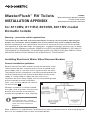
Installing Electronic Water Valve/Vacuum Breaker
Remote installation guidelines
Several MasterFlush toilet models include an electronic water
valve/vacuum breaker assembly that must be installed in the
water supply line at a location that is separate from the toilet.
The purpose of this component is to eliminate the potential for
water to siphon backward from the toilet bowl into the water
supply if a sharp drop in supply line pressure occurs.
To protect the fresh water supply, the vacuum breaker portion
of the assembly must be installed at
least 1 inch (25 mm) above the ceramic
rim of the toilet
1
.
Whether installed in a cabinet, behind
or inside a wall, the water valve/vacuum
breaker also must be accessible for
maintenance purposes if ever required.
1
Note
Use cold water only. Include
shut-off valve in water line before
water valve for maintenance
purposes.
Refer to Section 4.2 and Section 5 of MasterFlush toilet installation manual, and wiring diagram/
parts list for complete toilet system installation details.
Includes:
Water valve/vacuum breaker installation
RV toilet system layouts
Wiring/electrical connection information

Dometic MasterFlush ToiletsRV Installation Appendix
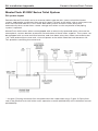
MasterFlush 8100RV Series Toilet System
RV system layout
Dometic MasterFlush 8100 series macerator toilets operate with a pressurized freshwater
system, and require a minimum ow rate of 2.0 gpm (7.6 lpm) at the toilet* with a static pressure
of 30-100 PSI/206-689 kPa. Fresh-water demand systems include a water pump that
automatically draws water from a water storage tank when a valve anywhere in the piping
system is opened.
MasterFlush 8100 series toilets are equipped with an electrically operated water valve and an
atmospheric vacuum breaker to prevent contamination of fresh water supplies. The system can
be equipped with a waste tank level monitor and shut-down relay that, when connected to the
“full” level probe of the waste tank, shuts off power to the toilet when the tank becomes full.
This prevents overlling the waste tank.
* 2.0 gpm (7.6 lpm) minimum flow rate published here supersedes the 2.5 gpm (9.5 lpm) flow
rate in the MasterFlush 8100 toilet series operation manual (600346375) and installation manual
(600346376).

Dometic MasterFlush Toilets RV Installation Appendix
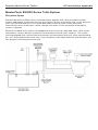
MasterFlush 8900RV Series Toilet System
RV system layout
Dometic MasterFlush 8900 series macerator toilets operate with a pressurized freshwater
system, and require a minimum ow rate of 2.0 gpm (7.6 lpm) at the toilet with a static pressure
of 30-100 PSI/206-689 kPa. Fresh-water demand systems include a water pump that
automatically draws water from a water storage tank when a valve anywhere in the piping
system is opened.
MasterFlush 8900 series toilets are equipped with an electrically operated water valve and an
atmospheric vacuum breaker to prevent contamination of fresh water supplies. The system
can be equipped with a waste tank level monitor and shut-down relay that, when connected to
the “full” level probe of the waste tank, shuts off power to the toilet when the tank becomes full.
This prevents overlling the waste tank.

Dometic MasterFlush ToiletsRV Installation Appendix
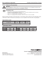
CONVERSION TABLE
Wire – AWG to mm
2
Feet to Meters
AWG 14 12 10 Ft 10 15 20 30 50
mm
2
2.5 4.0 6.0 M 3.1 4.6 6.1 9.2 15.2
Wire size per length of run* 0-15 ft. 16-30 ft. 31-50 ft.
12 volts DC #14 #12 #10
* Distance from circuit breaker to electronic control module.
WIRE SIZING CHART
When installing a Dometic macerator toilet in a recreation vehicle, please use the following wiring
information. Refer to MasterFlush toilet parts list for complete macerator toilet wiring diagram.
Installation notes
• Each toilet must have its own circuit breaker or fuse.
• Wire sizes must be appropriate for the installation. All other installation factors must be in
accordance with ISO electrical standards.
• Always use stranded copper wire (preferably tinned).
• Always use crimp-type wire connections. Do not use wire nuts (they corrode).
Warning!
Hazard of Shock or Fire: Always use recommended fuse, circuit breaker and wire size.
Failure to do so can cause the loss of property and life.
Wiring / Electrical Connections
Dometic Corporation, Sanitation Division
13128 State Rt. 226, P.O. Box 38
Big Prairie, OH 44611 USA
1-800-321-9886 • Fax: 330-496-3097
www.Dometic.com
REVISION A
Form No. 600346694 8/17
©2017 Dometic Corporation
-
 1
1
-
 2
2
-
 3
3
-
 4
4


Dometic MasterFlush 8110RV, 8111RV, 8910RV, 8911RV Toilets Installation guide
- Type
- Installation guide
- This manual is also suitable for
Ask a question and I''ll find the answer in the document
Finding information in a document is now easier with AI
Related papers
-
Dometic 8700 Series MasterFlush Installation guide
-
-
-
-
-
-
-
-
-