AirWave 8.2.3 and
Clarity Beta
User Guide
December 2016 | Rev. 01 AirWave 8.2.3 and Clarity Beta | User Guide
Copyright Information
© Copyright 2016 Hewlett Packard Enterprise Development LP
Open Source Code
This product includes code licensed under the GNU General Public License, the GNU Lesser General Public
License, and/or certain other open source licenses. A complete machine-readable copy of the source code
corresponding to such code is available upon request. This offer is valid to anyone in receipt of this information
and shall expire three years following the date of the final distribution of this product version by Hewlett-
Packard Enterprise Company. To obtain such source code, send a check or money order in the amount of US
$10.00 to:
Hewlett-Packard Enterprise Company
Attn: General Counsel
3000 Hanover Street
Palo Alto, CA 94304
USA
Please specify the product and version for which you are requesting source code.
You may also request a copy of this source code free of charge at: http://hpe.com/software/opensource.
AirWave 8.2.3 and Clarity Beta | User Guide Contents | iii
Contents
Overview 1
Contacting Support 1
Supported Infrastructure Devices 2
Synthetic Client-Capable Access Points 2
Initial Setup 3
System Requirements 3
Installing the Clarity Engine 3
Provisioning the Clarity Engine 4
Network Configuration 4
AirWave Server Configuration 7
NTP Server, Date, and Time Configuration 8
Time Zone Configuration 9
Post-Configuration Instructions 10
Changing the Root Password 10
Reconfiguring the Clarity Engine 11
Installing on Linux and VMware ESXi 12
RPM Commands 12
Using Clarity 13
Live Monitoring 13
About the Clarity Live Charts, Graphs, and Tables 13
Failures Rates 13
Process Times 13
First 25 Results 14
Thresholds for Failures and Process Times 14
User Details in Clarity 15
Authentication Failure Data 16
DHCP Failure Data 16
DNS Failure Data 17
Sorting and Filtering Clarity Data 17
Selecting a Folder from the Navigation Bar 18
Exporting Clarity Data 18
Changing the Time Range 18
Changing the Data Retention Interval 19
Evaluating User Status 19
Synthetic Testing 20
Adding the Clarity Engine 20
Viewing Clarity Engine Information and Graphs 21
Clarity Engine Information 21
Graphs 22
How to Set Up Your Synthetic Test 22
Selecting Your APs 22
Using Clarity Synthetic to select your client and target APs 23
Using VisualRF to select your client AP 24
Adding Basic Information to Your Test 25
Setting Up and Running Your Tests 26
iv | Contents AirWave 8.2.3 and Clarity Beta | User Guide
DNS Test 26
Ping Test 27
Page Load Test 27
Traceroute Test 28
iPerf3 Test 29
How to View Test Results 30
Viewing Test Results in VisualRF 30
Viewing Your Test Results in Clarity 31
Status Icons in Clarity Synthetic 31
Debugging Issues 32
Collecting Logs 32
Debugging on the Host 32
Example of a Heartbeat Message 33
Known Issues 34
AirWave 8.2.3 and Clarity Beta | User Guide Overview | 1
Chapter 3
Overview
This guide describes how to install and set up Clarity Engine and use Clarity Synthetic with your AirWave Network
Management System. This guide also provides information about known issues with Clarity Synthetic in AirWave
8.2.3.
For information about using AirWave, see the latest version of the AirWave 8.2 User Guide.
Contacting Support
Main Site arubanetworks.com
Support Site support.arubanetworks.com
Airheads Social Forums and Knowledge
Base
community.arubanetworks.com
North American Telephone 1-800-943-4526 (Toll Free)
1-408-754-1200
International Telephone arubanetworks.com/support-services/contact-support/
Software Licensing Site hpe.com/networking/support
End-of-life Information arubanetworks.com/support-services/end-of-life/
Security Incident Response Team (SIRT) Site: arubanetworks.com/support-services/security-bulletins/
Email: aruba-sirt@hpe.com
Table 1: Contact Information
AirWave 8.2.3 and Clarity Beta | User Guide Supported Infrastructure Devices | 2
Chapter 4
Supported Infrastructure Devices
AirWave provides a range of features to manage network infrastructure devices from Aruba Networks and other
vendors. For a complete list of supported products, see the AirWave 8.2 Supported InfrastructureDevices
document. You can find this document at support.arubanetworks.com.
Synthetic Client-Capable Access Points
AirWave supports synthetic testing for the following Aruba access points running ArubaOS 6.5.0.0 or later:
lAP-220 Series
lAP-210 Series
lAP-200 Series
AirWave supports synthetic testing for the following Aruba access points running ArubaOS 6.5.1.0 or later:
lAP-330 Series
lAP-320 Series
lAP-310 Series
lAP-300 Series
AirWave 8.2.3 and Clarity Beta | User Guide Initial Setup | 3
Chapter 5
Initial Setup
The Aruba Clarity Engine provides proactive analysis of end user quality of experience by monitoring critical
network services. This document describes how to install the Clarity Engine.
System Requirements
Listed below are the minimum hypervisor host system requirements for the Clarity Engine to run as a guest
virtual machine (VM) and the resources required for the VM to be functional:
lQuad-core Core i5 1.9 GHz processors with hyper threading enabled
l8 GB RAM
lMinimum 2 physical network interface cards (NICs) on the ESXi host
TheClarity Engine OVA template cannot be installed on the same virtual machine instance as AirWave. The
Clarity Engine needs its own virtual machine instance.
The following illustration shows the topology of the Clarity Engine in your network.
Figure 1: Clarity Engine Topology
Installing the Clarity Engine
You should install the Clarity Engine for AirWave deployment on VMware ESXi infrastructure using the Open
Virtual Format (OVF) template.
Copy the template to the client machine before importing the OVF template.
To install the Clarity Engine:
1. Log in to the vSphere ESXi Host using vSphere Client.
2. Click File > Deploy OVF Template. The Deploy OVF Template Wizard is displayed.
3. Click Browse to find the OVF file, then click Next. The OVF Template Details option in the left pane is
displayed.
4. Enter a name for the Clarity Engine, then click Next. This name should be distinguishable from the name of
the virtual host.
4| Initial Setup AirWave 8.2.3 and Clarity Beta | User Guide
Figure 2: Naming the Clarity Engine
5. Review the End User License Agreement and click Accept (see Figure 3).
Figure 3: Accepting the End User License Agreement
6. Follow the onscreen instructions, then click Finish.
Provisioning the Clarity Engine
When Clarity Engine first boots, the initial setup window displays, where you can configure network, AirWave,
NTP-related, and time zone settings.
Network Configuration
Follow these steps to configure the ethernet interface and DNS servers.
1. Select Network configuration, as shown in Figure 4.
Figure 4: Opening the Network Configuration Tool
2. Select Device configuration, as shown in Figure 5.
Figure 5: Selecting Device Configuration
3. Select an active network interface. Depending on your local host configuration, you might see a different
vendor name than the example shown in Figure 6.
Figure 6: Selecting an Active Network Interface
4. Enter the static IP address, netmask, default gateway IP address, DNS servers, and click Ok.Figure 7 shows an
example for the eth0 interface .
AirWave 8.2.3 and Clarity Beta | User Guide Initial Setup | 5
6| Initial Setup AirWave 8.2.3 and Clarity Beta | User Guide
Figure 7: Network Configuration
5. Click Save, as shown in Figure 8.
Figure 8: Saving the Network Configuration
6. Select DNS configuration.
7. Change the default hostname and the primary DNS server, then click Ok.
Figure 9: Configuring the DNS Servers
8. Click Save&Quit, as shown in Figure 10.
Figure 10: Saving the Device Configuration
AirWave Server Configuration
Follow these steps to configure the AirWave server.
1. From the initial setup window, select AirWave configuration, then click Enter, as shown in .
Figure 11: Opening the AirWave Configuration Tool
2. Click AirWave configuration, as shown in Figure 12.
Figure 12: Selecting the AirWave Configuration Tool
3. Enter the IP address to associate with the AirWave server, then click Ok. The Clarity Engine uses the default
port number 60001, as shown in Figure 13.
AirWave 8.2.3 and Clarity Beta | User Guide Initial Setup | 7
8| Initial Setup AirWave 8.2.3 and Clarity Beta | User Guide
Figure 13: Configuring the IP Address and Port
4. Click Save&Quit.
NTP Server, Date, and Time Configuration
You can configure an NTP server so that time is synchronized among the Clarity Engine, AirWave server, and
Aruba controller. Follow these steps to configure NTP servers and dynamic or static time.
If you do not want to configure NTP servers, go to step 4 on page 9 to configure static date and time. Ensure
that this date and time matches the date and time of the Airwave server.
1. From the initial setup window, select NTP DateTime configuration.
Figure 14: Opening the NTP DateTime Tool
2. Select NTP DateTime configuration, as shown in Figure 15, then click Enter.
Figure 15: Selecting NTP DateTime Configuration
3. Enter the NTP server host names, as shown in Figure 16.
Find time servers used by the NIST Internet Time Service (ITS) or pooled into zones by the NTP Pool Project.
Figure 16: Configuring NTP Servers
4. In the Use NTP Server field, toggle the asterisk off using the spacebar to manually change the date and time,
then click Ok (see Figure 17).
Figure 17: Configuring the Date and Time
5. Click Save&Quit.
Time Zone Configuration
Follow these steps to configure the time zone:
1. From the initial setup window, select Timezone configuration, as shown in Figure 18.
Figure 18: Opening the Timezone Configuration Tool
2. Select the time zone, then click Ok, as shown in Figure 19.
AirWave 8.2.3 and Clarity Beta | User Guide Initial Setup | 9
10 | Initial Setup AirWave 8.2.3 and Clarity Beta | User Guide
Figure 19: Configuring the Time Zone
3. From the initial setup window, click Quit to exit the setup.
You can start using Clarity Synthetic after you complete the post-configuration instructions and add the
Clarity Engine in AirWave.
Post-Configuration Instructions
After you complete the initial configuration:
1. Reboot the machine after completing the initial configuration.
2. Check IP connectivity to an external host after rebooting the machine.
After provisioning the Clarity Engine, add the Clarity Engine in AirWave. Then you are ready to use the Clarity
Engine for synthetic tests.
Changing the Root Password
After you deploy the OVA template, you need to change the default root password.
1. Log in as root to the Clarity Engine with user name (root) and password (admin).
2. Follow the onscreen instructions to change the default root password, as shown in Figure 20.
Figure 20: Changing the Root Password
Reconfiguring the Clarity Engine
If you need to reconfigure the Clarity Engine, you can use the setup command to open the intial setup window.
1. Open a terminal window and type setup.
Figure 21: Entering the Setup Command
The intial setup window opens.
Figure 22: Initial Setup Window
2. Follow the instructions in "Provisioning the Clarity Engine" on page 4.
3. After making the configuration changes, restart the network using the service network restart command.
AirWave 8.2.3 and Clarity Beta | User Guide Initial Setup | 11
AirWave 8.2.3 and Clarity Beta | User Guide Installing on Linux and VMware ESXi | 12
Chapter 6
Installing on Linux and VMware ESXi
This section provides information for upgrading the Clarity Engine software.
RPM Commands
You can upgrade the Clarity Engine using the following command:
rpm -Uf CE-1.0.0.0-iso.x86_64.rpm
AirWave 8.2.3 and Clarity Beta | User Guide Using Clarity | 13
Chapter 7
Using Clarity
AirWave provides more ways to monitor your Clarity data and network performance. You can monitor Wi-Fi
connectivity in real-time with Clarity Live, so you can find problems in the wireless client association,
authentication, IP address configuration, and DNS resolution processes. You can also turn APs into wireless
clients in order to run synthetic tests in Clarity Synthetic mode.
AirWavereceives Clarity Live data through AMON messages sent from controllers on the network. The
controllersmust be running ArubaOS 6.4.3 or later.
Live Monitoring
The Clarity Live information on the Home > Clarity page provides a way to observe wireless clients as they
connect to the wireless network. Live monitoring helps you determine the cause of network connectivity and
performance issues.
About the Clarity Live Charts, Graphs, and Tables
The Clarity Live dashboard displays real-time information that helps you identify failure when clients are
connecting to the wireless network. You can drill down and view data for devices associating to APs in a specific
subfolder, or view data for a different time interval.
Failures Rates
Figure 23 shows an example of the statistics displayed in the dashboard. Statistics include:
lPercentage of failures for each process
lNumber of failures
lTotal number of attempts (both failed and successful) over the selected time period.
Figure 23: Home > Clarity Dashboard Showing Failure Rates
Process Times
To display the average process times over the selected time interval, click the Failure drop-down menu in the
upper left corner of the dashboard and click Time.
14 | Using Clarity AirWave 8.2.3 and Clarity Beta | User Guide
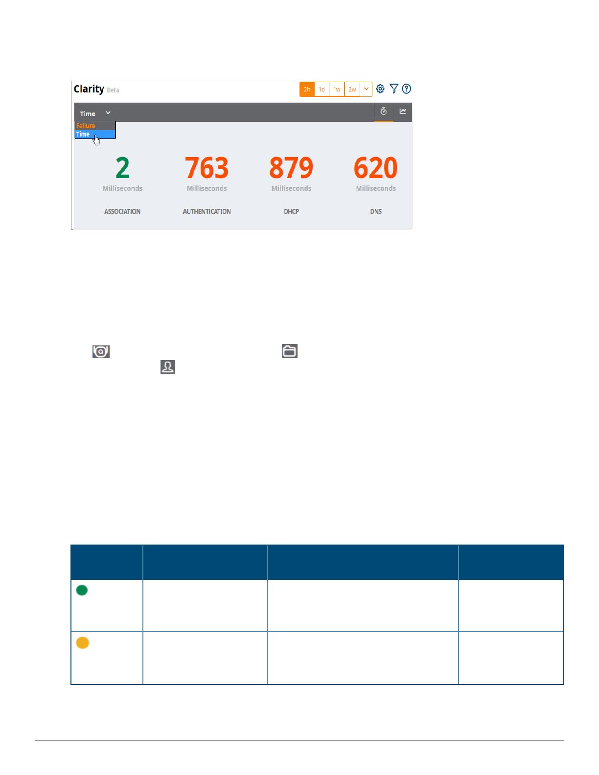
Figure 24: Home > ClarityDashboard Showing Average Process Times
First 25 Results
Clarity Live displays only 25 subfolders and APs with the lowest performance levels. If you have more than 25
subfolders or APs in the folder view, you can increase the number of results returned per page.
To see more than 25 results:
1. Click the Details link at the bottom right corner of a Clarity table. A Details pop up window appears.
2. Click the per page drop down list in the lower left corner of the window and select the number of results.
Click to view information about APs, or click to return to the default folder view. To see the top 25 users
by Clarity issue, click at the top right of the Summary table.
Thresholds for Failures and Process Times
Each icon in the Summary table represents quality thresholds for the number failures and the average amount
of time it takes the process to complete.
For example, if a process has a high failure rate but a good process time, the icon will be red, indicating the most
severe threshold crossed in either category. Hover your mouse over an icon to display the number of
authentication process failures and successes for clients associating to individual APs or folders of APs, as well as
the average time it took for each process to complete.
Refer to Table 2 for descriptions of what each icon color represents and the thresholds for process times and
failure rates.
Icon Color Description Process Time Thresholds Failure Rate
Threshold
Good failure rate and
process time
lGood Association time: <10 ms
lGood Authentication time: <500ms
lGood DHCP time: <100 ms
lGood DNS time: <100 ms
< 10% failures
Fair failure rate or process
time
lFair Association time: 10 -20 ms
lFair Authentication time: 500-1000ms
lFair DHCP time: 100 - 200ms
lFair DNS time: 100 -200ms
>10% to 20% failures
Table 2: Icon Color Codes and Thresholds
Icon Color Description Process Time Thresholds Failure Rate
Threshold
Poor failure rate or process
time.
lPoor Association time: >20 ms
lPoor Authentication time: >1000 ms
lPoor DHCP time: >200 ms
lPoor DNS time: >200ms
>20% failures
Table 2: Icon Color Codes and Thresholds (Continued)
User Details in Clarity
Clarity Live allows you to use the Summary table to navigate directly to user details. For example, you can
narrow your results to list users that have used a specific server to authenticate, and you can click the Client
MAC address link to open the User Detail page for the client.
To view user details for a client:
1. In the Summary table on the Home >Clarity page, locate a client and click in the Authentication column
(see Figure 25). Or, you can open the User Details page by clicking Association or DHCP.
Figure 25: Opening the User Details Page for a Client
The User Details page opens (see Figure 26).
Figure 26: Clarity User Details
2. Narrow the scope of your analysis, by selecting a link from the User Details page. For example, to see
authentication failures for all users who have used a specific Dot1x server, click Auth. Failures (%) for the
server (see Figure 27).
AirWave 8.2.3 and Clarity Beta | User Guide Using Clarity | 15
16 | Using Clarity AirWave 8.2.3 and Clarity Beta | User Guide
Figure 27: Filtering Your Results
The User Details page displays filtered results (see Figure 28).
Figure 28: Filtered User Details for Authentication Failures for Users on a Dot1x Server
Authentication Failure Data
The Authentication table provides information for the client authentication processes on the network.
Column Description
Servers IP address of an authentication server.
Type Indicates the authentication server type:
lDot1x: 802.1x
lCaptive Portal: Captive portal authentication
lMAC Auth:MAC authentication
lWPA-PSK: WPA encryption with pre-shared key (PSK) authentication
Failures (%) This column shows the percentage of authentication failures for that server, followed by the total
number of failures and the total number of authentication attempts over the selected time
interval.
Avg. Time (ms) The average time it took to successfully complete the authentication process over the selected
time interval. Times for both failed and successful attempts are calculated in this average.
Table 3: Authentication Table fields
Click in the table heading to display of graph of average authentication times for each server during the
selected time interval. Hover your mouse over any section of the graph to view details about the authentication
times during that portion of the time interval, or click to return to the table view.
DHCP Failure Data
The DHCP table on the Home>Clarity page provides information about authentication on the network.
  • Page 1 1
  • Page 2 2
  • Page 3 3
  • Page 4 4
  • Page 5 5
  • Page 6 6
  • Page 7 7
  • Page 8 8
  • Page 9 9
  • Page 10 10
  • Page 11 11
  • Page 12 12
  • Page 13 13
  • Page 14 14
  • Page 15 15
  • Page 16 16
  • Page 17 17
  • Page 18 18
  • Page 19 19
  • Page 20 20
  • Page 21 21
  • Page 22 22
  • Page 23 23
  • Page 24 24
  • Page 25 25
  • Page 26 26
  • Page 27 27
  • Page 28 28
  • Page 29 29
  • Page 30 30
  • Page 31 31
  • Page 32 32
  • Page 33 33
  • Page 34 34
  • Page 35 35
  • Page 36 36
  • Page 37 37
  • Page 38 38
  • Page 39 39
  • Page 40 40

Ask a question and I''ll find the answer in the document

Finding information in a document is now easier with AI