Page is loading ...

Revision V2.1/June 2010
©2010 Semtech Corp.
SX8650EVK
www.semtech.com
Page 1
ADVANCED COMMUNICATIONS & SENSING
USER GUIDE
Touch
Screen
Interface
SX8650
VDD
AUX
X+
Y+
X-
Y-
A0
NIRQ
NRST
SCL
SDA
GND
HOST
Control
I2C
Digital
Filter
ref+
ref-
ADCin out
OSCPOR
Vref
SX8650 Evaluation Kit
User’s Guide

Revision V2.1/June 2010
©2010 Semtech Corp.
SX8650EVK
www.semtech.com
Page 2
Section Page
ADVANCED COMMUNICATIONS & SENSING
USER GUIDE
Table of contents
1. General Description................................................................................................................................................. 3
2. Hardware Description .............................................................................................................................................. 3
2.1. Overview.......................................................................................................................................................... 3
2.2. Content ............................................................................................................................................................ 3
2.3. Board .............................................................................................................................................................. 3
2.3.1. Connection to the SX8650 ........................................................................................................................ 3
2.4. Power and analog Interface............................................................................................................................. 4
2.5. Digital Interface................................................................................................................................................ 5
3. Software Description................................................................................................................................................ 5
3.1. Overview.......................................................................................................................................................... 5
3.2. Installation........................................................................................................................................................ 5
3.3. Connecting the EVK......................................................................................................................................... 5
3.4. Starting the GUI ............................................................................................................................................... 6
3.5. Measurements................................................................................................................................................. 6
3.5.1. Overview ................................................................................................................................................... 6
3.5.2. Auxiliary Channel ...................................................................................................................................... 6
3.6. Throughput....................................................................................................................................................... 7
3.6.1. Overview ................................................................................................................................................... 7
3.7. Touch Screen Setup ........................................................................................................................................ 8
3.7.1. Overview ................................................................................................................................................... 8
3.8. I2C Setup......................................................................................................................................................... 8
3.8.1. Overview ................................................................................................................................................... 8
3.9. Extras............................................................................................................................................................... 9
3.9.1. Overview ................................................................................................................................................... 9
3.10. Display Registers........................................................................................................................................... 10
3.10.1. Overview ................................................................................................................................................. 10
3.11. Convert .......................................................................................................................................................... 11
3.11.1. Overview ................................................................................................................................................. 11
3.12. View Graph / View Touch Screen.................................................................................................................. 11
3.12.1. Overview ................................................................................................................................................. 11
3.13. Clear Data...................................................................................................................................................... 12
3.13.1. Overview ................................................................................................................................................. 12
3.14. Change Operation Mode................................................................................................................................ 12
3.14.1. Overview ................................................................................................................................................. 12
3.15. Connected/Disconnected............................................................................................................................... 12
3.15.1. Overview ................................................................................................................................................. 12
3.16. Quit ................................................................................................................................................................ 12
3.16.1. Overview ................................................................................................................................................. 12
3.17. Schematics .................................................................................................................................................... 13
3.18. Board outline.................................................................................................................................................. 14
4. References ............................................................................................................................................................ 14

Revision V2.1/June 2010
©2010 Semtech Corp.
SX8650EVK
www.semtech.com
Page 3
ADVANCED COMMUNICATIONS & SENSING
USER GUIDE
1. General Description
This user’s guide describes the characteristics, operation, and use of the SX8650EVK. This evaluation module is a 4-wire
touch screen controller which also has auxiliary input. The hardware and software description and the schematic diagram
are included.
2. Hardware Description
2.1. Overview
The SX8650EVK is the board for evaluation of the 4-wire resistive touch screen controller SX8650. Since SX8650EVK is
provided with a touch-panel, it is easy to check the functionality of the chip.
The EVK and its supporting documentation allows for customers to develop software that can be used in eventual
implementations. No external supply is needed to power the board. A USB cable is provided to connect the EVK to a
Windows based PC for operation of the software.
2.2. Content
The evaluation kit is composed of the following parts:
The board with the SX8650 and the touch screen on the top
A USB cable to connect the board to the PC
A CDROM with the installation files and the user guide
A stylus to write on the touch screen
2.3. Board
The board is split in 2 areas. From the bottom view (component side), the left area is the interface between the USB of the
PC and the SX8650. The right area is dedicated to the SX8650 and the touch screen connectors.
The S_ON switch is the SX8650 power supply switch. A red led is lighted in the ON position. When it is switch off the
SX8650 is not supplied but the interface circuitry is still powered on.
2.3.1. Connection to the SX8650
The left side of JP1 (odd number) is connected to the SX8650 host and the power pins.
The right side of JP1 (even number) is connected to the interface pins of the SX8650.
The jumpers allow the connection between the host and the SX8650. If an external host, power supply, or auxiliary input
should be used, the jumper would be removed.
Table 1 JP1 Pinout
Pin Number Signal Description
JP1(1-3) GND_0 Ground
JP1(3-4) V3V3 1.85V, 3.3V or external supply voltage
JP1(5-6) V3V3PU Unused
JP1(7-8) SCL I2C bus serial clock
JP1(9-10) SDA I2C bus data line
JP1(11-12) NRST SX8650 Reset pin
JP1(13-14) NIRQ SX8650 interrupt pin
JP1(15-16) A0 SX8650 I2C address selection
JP1(17-18) AUX SX8650 Auxiliary input
JP1(19-20) V3V3reg Unused

Revision V2.1/June 2010
©2010 Semtech Corp.
SX8650EVK
www.semtech.com
Page 4
ADVANCED COMMUNICATIONS & SENSING
USER GUIDE
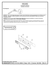
J3 header gives access to the J1 or J4 touch screen connectors. The jumpers set in the left vertical row of J3 enable the
connection to J1 connector.
The jumpers set in the horizontal way of J3 enable the connection to J4 connector.
A direct connection via J3 can also be made to adapt other panel connections.
Table 2: J3 pinout
Figure 1. Connection for J1 or J4 connectors
2.4. Power and analog Interface
For maximum flexibility, the SX8650EVK is designed for easy interfacing to multiple analog-sources.
The board is powered from the USB. The S_V switch allows the user to test the SX8650 to 3.3V (switch to the left) or 1.85V
(switch to the right).
If the user want to test the chip with a different supply voltage then the jumper JP1 (3-4) should be removed and an
external voltage connected to JP1 (4). The SX8650 supply voltage range goes from 1.65V to 3.7V.
JP1 (18) gives access to the AUX input.
If the AUX input of the SX8650 is configured as an analog input, an arbitrary signal generator or any analog signal can be
connected on JP1(18).
If the AUX input of the SX8650 is configured to be used as a trigger for conversion, then a square wave generator or any
digital signal can be connected to JP1(18).
Pin Number Signal Description
J3(3) Y- 4-wire touch screen Y- plate voltage supply
J3(7) X- 4-wire touch screen X- plate voltage supply
J3(11) Y+ 4-wire touch screen Y+ plate voltage supply
J3(15) X+ 4-wire touch screen X+ plate voltage supply
J3(17-19) GND_0 Ground
Y-
X-
Y+
X+
GND
Y-
X-
Y+
X+
GND
Connection through J1 Connection through J4

Revision V2.1/June 2010
©2010 Semtech Corp.
SX8650EVK
www.semtech.com
Page 5
ADVANCED COMMUNICATIONS & SENSING
USER GUIDE
2.5. Digital Interface
JP1 header also gives access to the digital control and serial data pins of the SX8650.
If an external host is used to test the part, the jumpers JP1 (7-8), JP1 (9-10), JP1 (11-12), JP1 (13-14) should be removed
and the SCL, SDA, NRST and NIRQ signals respectively connected to JP1 (8), JP1 (10), JP1 (12), JP1 (14).
3. Software Description
3.1. Overview
The software is constructed with graphical aids such as radio buttons and check boxes so each setting on the device can
easily be seen in a human readable display along with what the particular setting means. No experience in software
programming is needed to operate the EVK or the SX8650 basic functions.
3.2. Installation
This software requires a Windows 2000/XP/Vista operating system. The software is installed via an installation program.
This is called “SX8650EvaluationKitSetup.exe”. The software will check to see if .NET 3.5 (which is required for the
software) is installed. If it is not, the program will download it from Microsoft and install .NET (NOTE: A reboot may be
required). After the software is installed, FTDI drivers will automatically be (re)installed. After the software is installed, you
should plug the USB connection from the EVK to the PC to complete the installation.
Figure 2. First launch of the SX8650 GUI
Before starting the installation, the EVK must be connected through the USB to the PC and recognized by Windows. By
default, the setup program will install a shortcut to the software in your start menu.
3.3. Connecting the EVK
The USB cable that is provided will connect the EVK to the PC. The S_ON switch should be on the ON position. If the GUI
is launched without an EVK connected and switched on, the program will show in the status that it is not connected. The

Revision V2.1/June 2010
©2010 Semtech Corp.
SX8650EVK
www.semtech.com
Page 6
ADVANCED COMMUNICATIONS & SENSING
USER GUIDE
GUI will still show all features available and can be used as a quick demonstration or for specific debug operations. In order
to connect the device once the GUI has been launched, the user must first connect the EVK to the PC via the USB cable.
3.4. Starting the GUI
After starting the GUI, a script will set the device to go into Pen Trigger Mode, enable X-Y to be measured, and then set up
a small power delay. NOTE: Pen Trigger Mode is not selected on startup because this is a command and not a register.
Commands cannot be read, whereas registers can be read.
Please do not disconnect the device while running the GUI. If it is desired to disconnect the EVK, close the GUI first.
3.5. Measurements
3.5.1. Overview
Figure 3. : Measurements
By clicking Measurements, the GUI will allow the user to select what channels to read. If the user is in Manual Conversion
Mode and select Auxiliary Channel, a popup will appear to allow determining how to use the Auxiliary Channel.
3.5.2. Auxiliary Channel
3.5.2.1. Overview

Revision V2.1/June 2010
©2010 Semtech Corp.
SX8650EVK
www.semtech.com
Page 7
ADVANCED COMMUNICATIONS & SENSING
USER GUIDE
Figure 4. Auxiliary Channel
When in Manual Conversion Mode, the user may use the AUX pin as a trigger to perform conversions or as a standard
analog input.
3.6. Throughput
3.6.1. Overview
Figure 5. Throughput

Revision V2.1/June 2010
©2010 Semtech Corp.
SX8650EVK
www.semtech.com
Page 8
ADVANCED COMMUNICATIONS & SENSING
USER GUIDE
The throughput page allows the user to change items that would affect the throughput of the device. Items such as Power
Delay and Set Delay may need to be changed from the default value depending on the touch screen used. NOTE: Set
Delay is similar to Power Delay but only used when a filter is selected.
3.7. Touch Screen Setup
3.7.1. Overview
Figure 6. Touch Screen Setup
When using different touch screens, the Touch Screen Setup page may need to be used. Currently, it will setup
Resistances on the X/Y planes which are used in calculating the pressure and also for determining the correct aspect ratio
for the screen size. Pressure Sensitivity is the number to multiply the final pressure calculation. This creates a larger pen
size for smaller pressure measurements. The default settings correspond to the touch screen used on the EVK.
3.8. I2C Setup
3.8.1. Overview

Revision V2.1/June 2010
©2010 Semtech Corp.
SX8650EVK
www.semtech.com
Page 9
ADVANCED COMMUNICATIONS & SENSING
USER GUIDE
Figure 7. I2C Setup
This page is normally not needed but is available in case the user wants to try different I2C frequency settings. However,
since the GUI is using Windows and a USB connection, there is a delay in between I2C commands because of the
Operating System.
3.9. Extras
3.9.1. Overview
Figure 8. Extras
This area allows different demonstration modes to try out the touch screen with. Currently there is only one other mode,
Touchpad Mode.

Revision V2.1/June 2010
©2010 Semtech Corp.
SX8650EVK
www.semtech.com
Page 10
ADVANCED COMMUNICATIONS & SENSING
USER GUIDE
3.9.1.1. Touchpad Mode
This mode allows the touch screen to act similar to a standard touchpad.
There are:
Left and Right Buttons
Edge moving (this is when the user moves the finger to an edge and the mouse still moves in that direction.
Left Clicking when just touching the touchpad area really fast.
Dragging (when the user double clicks fast and on the second click moves around on the touchpad).
All settings such as speed and button configuration (swapping of left and right buttons) are done through the control
panel in the standard mouse section.
3.10. Display Registers
3.10.1. Overview
Figure 9. Display Registers
If the user desires to view or modify the registers manually, he/she may do so on the Display Registers page.

Revision V2.1/June 2010
©2010 Semtech Corp.
SX8650EVK
www.semtech.com
Page 11
ADVANCED COMMUNICATIONS & SENSING
USER GUIDE
3.11. Convert
3.11.1. Overview
Figure 10. Pen Detection Mode with the Pen Down
The Select/Convert button is only available when in Manual Conversion Mod. This will perform a conversion with the
channels selected on the Measurements page.
3.12. View Graph / View Touch Screen
3.12.1. Overview
Figure 11. After user clicks View Graph and has touched the screen
The user may view a graph display of the data. To go back to a touch screen view, just click View Touch Screen

Revision V2.1/June 2010
©2010 Semtech Corp.
SX8650EVK
www.semtech.com
Page 12
ADVANCED COMMUNICATIONS & SENSING
USER GUIDE
3.13. Clear Data
3.13.1. Overview
This button is only available when viewing the touch screen. The only function of it is to clear the screen.
3.14. Change Operation Mode
3.14.1. Overview
Clicking Change Operation Mode will allow the user to change the operation mode. The GUI will start up with this same
page.
3.15. Connected/Disconnected
3.15.1. Overview
Clicking Connected will disconnect the EVK. When it says Disconnected, clicking the button causes a connect to occur.
3.16. Quit
3.16.1. Overview
Clicking the Quit button will close out the GUI.

Revision V2.1/June 2010
©2010 Semtech Corp.
SX8650EVK
www.semtech.com
Page 13
ADVANCED COMMUNICATIONS & SENSING
USER GUIDE
3.17. Schematics
1
1
2
2
3
3
4
4
D D
C C
B B
A A
Title
Number RevisionSize
A4
Date: 4/8/2009 Sheet of
File: U:\users\..\sx8650.SCH Drawn By:
SX8650 EVK V1a - I2C Application
PCB-E134V02a
V2a
ONi
1/1
EESK
1
EEDATA
2
VCC
3
RESET#
4
RSTOUT#
5
3V3OUT
6
USBDP
7
USBDM
8
GND
18
VCCIOA
14
GND
25
VCC
42
XTIN
43
XTOUT
44
AGND
45
AVCC
46
TEST
47
EECS
48
GND
34
GND
9
VCCIOB
31
ADBUS0
24
ADBUS1
23
ADBUS2
22
ADBUS3
21
ADBUS4
20
ADBUS5
19
ADBUS6
17
ADBUS7
16
ACBUS0
15
ACBUS1
13
ACBUS2
12
ACBUS3
11
SI/WUA
10
BDBUS0
40
BDBUS1
39
BDBUS2
38
BDBUS3
37
BDBUS4
36
BDBUS5
35
BDBUS6
33
BDBUS7
32
PWREN#
41
BCBUS0
30
BCBUS1
29
BCBUS2
28
BCBUS3
27
SI/WUB
26
U2
FT2232D
CS
1
SCL
2
D
3
Q
4
GND
5
ORG
6
DU
7
VCC
8
U3
M93C46WMN6
Ferrite
F4
27RR6
27R
R7
VUSB
VUSB
1.5kR9
33nF
C17
470R
R3
100nF
C16
33pF
C21
33pF
C22
100nF
C4
1uF
C3
1uF
C1
100nF
C2
100nF
C5
1k
R1
PWREN#
PWREN#
VUSB
10k
R13
2.2k
R12
47k
R31_1
27k
R2
2 1
Q1
xtal
V3V1reg
100nF
C23
10uF
C18
47pF
C20
47pF
C19
100nF
C11
33nF
C12
3
1
2
U11
MOSFET-P
100nF
C14
Ferrite
F3
V3V1reg
V3V1reg
1uF
C9
100nF
C8
V3V1PU
V3V1
D_APP
LED
470R
R73
10nF
C13
1 2
W_USB
Jumper
SDA
1
SCL
2
TOUT
3
GND
4
A2
5
A1
6
A0
7
VDD
8
U4
DS1631
100nF
C24
V3V1reg
F_SDA
F_SCL
TOUT
TOUT
F_NRST
10k
R10
10k
R11
V3V1reg
NRST
2.2k
R5
NC
R4
V3V1
SCL
2.2k
R8
NC
R18
V3V1reg
SDA
F_SDA
F_SCL
NC
RP1
RPot
SHDN
1
ADJ
3
GND
2
OUT
4
IN
5
U1
SC1563
APP_TRIG(0)
1.0nF
C46
100nF
C47
NIRQ
SCL
SDA
NC
R40
S_ON
GND3
Ferrite
F1
Ferrite
F2
Ferrite
F7
Ferrite
F8
Ferrite
F5
Ferrite
F6
VBUS
1
D-
2
D+
3
GND
5
x
4
SHLD
6
SHLD
7
SHLD
8
SHLD
9
J2
Mini USB Type-B
APP_TRIG(1)
APP_TRIG(2)
VDD
1
X+
2
Y+
3
X-
4
Y-
5
GND
6
NIRQ
7
SDA
8
SCL
9
NRST
10
A0
11
AUX
12
U9
SX8650
V3V1reg
100nF
C7
1uF
C6
1uF
C10
100nF
C15
43k
R15
27k
R14
SHDN
1
ADJ
3
GND
2
OUT
4
IN
5
U5
SC1563
1 2
3 4
5 6
7 8
9 10
11 12
13 14
15 16
17 18
19 20
JP1
MALE HEAD ER 10X2
15k
R31_2
S_V
F_AUX
F_A0
F_NIRQ
10k
R23
10k
R24
10k
R25
F_NRST
F_SDA
F_SCL
F_AUX
F_A0
F_NIRQ
GND_USBa
GND_USBa
GND_USBa
GND_USBa
GND_USBa
GND_USBa
GND_USBa
GND_USBa
GND_USBa
GND_USBa
GND_USBa
GND_USBa GND_USBa
GND_r
GND_0
GND_r GND_0
V3V1PU
GND_r
GND_r
GND_r
GND_r
GND_r
GND_USBa
GND_USBa
GND_r
V3V1reg
10k
R22
100nF
C25
NC
R21
NC
R19
10k
R20
NC
R16
10k
R17
V3V1PU
V3V1PU
V3V1PU
V3V1PU
GND_0
GND_0
GND_0
GND_0
AUX
A0
GND_0
GND_0
NRST
NIRQ
AUX
A0
1
2
3
4
J1
Tyco 84952-4
V3V1reg
X+
X-
Y-
Y+
X+
X-
Y-
Y+
1
2
3
4
J4
Omron XF2U-0415-3A
GND_0
220pF
C26
GND_r
1uF
C27
GND2
GND1
S_NRES
1 2
3 4
5 6
7 8
9 10
11 12
13 14
15 16
17 18
19 20
J3
MALE HEAD ER 10X2
X+_J1
X-_J1
Y-_J1
Y+_J1
X+_J1
X-_J1
Y-_J1
Y+_J1
X+_J4
X-_J4
Y-_J4
Y+_J4
X+_J4
X-_J4
Y-_J4
Y+_J4

Revision V2.1/June 2010
©2010 Semtech Corp.
SX8650EVK
www.semtech.com
Page 14
ADVANCED COMMUNICATIONS & SENSING
USER GUIDE
3.18. Board outline
4. References
[1] SX8650 Datasheet

Revision 1.0 / June 2010
©2010 Semtech Corp.
SX8652
www.semtech.com
Page 15
ISO9001
CERTIFIED
ADVANCED COMMUNICATIONS & SENSING
USER GUIDE
© Sem tech 2010
All rights reserved. Reproduction in whole or in part is prohibited without the prior written consent of the copyright owner. The
inform ation presented in this docum ent does not form part of any quotation or contract, is believed to be accurate and reliable
and m ay be changed without notice. N o liability will be accepted by the publisher for any consequence of its use. P ublication
thereof does not convey nor im ply any license under patent or other industrial or intellectual property rights. Sem tech assum es
no responsibility or liability whatsoever for any failure or unexpected operation resulting from m isuse, neglect im proper
installation, repair or im proper handling or unusual physical or electrical stress including, but not lim ited to, exposure to
param eters beyond the specified m axim um ratings or operation outside the specified range.
SE MTECH PR OD UCTS ARE NOT D ESIG NED, IN TEN DED, A UTH O RIZED O R W AR RA NTE D TO BE SUITAB LE FO R U SE IN
LIFE-SUPPO RT APPLIC ATIO NS, DEVIC ES OR SYS TE MS OR O THER C RITIC AL APPLIC ATIO N S. INC LUSIO N OF
SE MTECH PRO D UCTS IN SU CH APP LIC ATIO NS IS UN DERS TO OD TO B E UN D ER TA KEN SO LELY AT THE C USTO MER’S
OW N RISK. Should a custom er purchase or use S em tech products for any such unauthorized application, the custom er shall
indem nify and hold Sem tech and its officers, em ployees, subsidiaries, affiliates, and distributors harm less against all claim s,
costs dam ages and attorney fees which could arise.
All referenced brands, product nam es, service nam es and tradem arks are the property of t
heir respective owners.
Semtech Corporation Advanced Communications & Sensing Products
Contact information
E-mail: [email protected]@semtech.comInternet: http://www.semtech.com
USA 200 Flynn Road, Camarillo, CA 93012-8790.
Tel: +1 805 498 2111 Fax: +1 805 498 3804
FAR EAST 12F, No. 89 Sec. 5, Nanking E. Road, Taipei, 105, TWN, R.O.C.
Tel: +886 2 2748 3380 Fax: +886 2 2748 3390
EUROPE Semtech Ltd., Units 2 & 3, Park Court, Premier Way, Abbey Park Industrial Estate, Romsey, Hampshire, SO51 9DN.
Tel: +44 (0)1794 527 600 Fax: +44 (0)1794 527 601
/