Lutron Electronics DT-2289 Operating instructions
- Category
- Measuring, testing & control
- Type
- Operating instructions

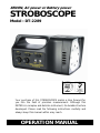
XENON, AC power or Battery power
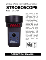
STROBOSCOPE
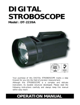
Model : DT-2289
Your purchase of this STROBOSCOPE marks a step forward for
you into the field of precision measurement. Although this
METER is a complex and delicate instrument, its durable structure
developed. Please read the following instructions carefully and
always keep this manual within easy reach.
OPERATION MANUAL

Warning
Do not look directly at strobe/reflector.
Light pulses at the frequency greater than
5 Hz may cause photosensitvie epilepsy in
some individuals if directly viewed.
A feature of the instrument is to make
moving objects appear to be stationary.
Precaution should therefore be taken to
ensure that there is no physical contact
made with objects being viewed.

Caution Symbol
Caution :
* Risk of electric shock !
Caution :
* Do not use fingers or any tool
to touch the FLASH TUBE.
* The instrument contains no user
serviceable parts and should not
be opened by the user.
* Repair or after service should be
done by a qualified technician
only.
* Power plug should apply the correct
ACV power voltage
* Operating duty cycle should be
adhered to.
* Cleaning - Only use the dry cloth to
clean the plastic case !
Environmental Condition
* Comply with EN61010 Installation
category II 300 Vac.
* Pollution Degree 2.
* Altitude up to 2000 meters.
* Indoor use.
* Relative humidity 80% max.

TABLE OF CONTENTS
1 FEATURES.................................................................1
2 SPECIFICATIONS.......................................................2
3 FRONT PANEL DESCRIPTION.....................................
.
6
3-1 Power On/Off Switch............................................8
3-2 DC9V Power Adapter Input Socket........................8
3-3 Hi
g
h, Low Ran
g
e Switch.......................................8
3-4 Stroboscope, Ext. Tri
gg
er, Tachometer Switch.......8
3-5 Photo Tach, Contact Tach, ft/min.. m/min SW.......8
3-6 Coarse Ad
j
ust Knob.............................................
.
8
3-7 Fine Ad
j
ust Knob.................................................
.
8
3-8 Ext. Tri
gg
er Input Socket.....................................
.
8
3-9 Contact Tach. Probe Input Socket.........................8
3-10 Front Cover Screws............................................8
3-11 Flash Tube and Tube Socket...............................8
3-12 Laser Li
g
ht Beam for Photo Tachometer..............8
3-13 Sensin
g
Sensor for Photo Tachometer.................8
3-14 Display..............................................................8
3-15 Tar
g
et Indicator.................................................8
3-16 Handle..............................................................
.
8
3-17 Battery Cover/Battery Compartment....................8
4. POWER SUPPLY CONSIDERATION..............................9
5. STROBOSCOPE MEASURING PROCEDURES.................10
5-1 Preparation........................................................
.
10
5-2 Checkin
g
Speed..................................................11
5-3 Checkin
g
Motion.................................................12
6. LASER PHOTO TACHOMETER MEASURING
PROCEDURES...........................................................13
7. CONTACT TACHOMETER ( Optional probe )
MEASURING PROCEDURES........................................14
8. FLASH TUBE REPLACEMENT......................................
.
16
9. THE ADDRESS OF AFTER SERVICE CENTER
CONSIDERATION....................................................17

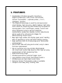
1. FEATURES
* Combination Stroboscope with 3 functions :
Digital Stroboscope, Laser Photo Tachometer,
Contact Tachometer ( optional probe ), 3 in 1 ,
intelligent function.
* The Digital Stroboscope is used the microprocessor
circuit design, high accuracy, digital readout, light duty,
that is ideal for inspecting and measuring the speed of
moving gears, fans, centrifuges, pumps, motors and
other equipment used in general industrial
maintenance, production, quality control, laboratories
and as well as for schools and colleges for
demonstrating strobe action.
* Back light high visible LCD display gives exact reading
with no guessing or error and saves battery energy.
* High precision both for Stroboscope and Tachometer
measurement.
* Xenon flash tube with plug and socket, easy to make
the tube replacement.
* Use an exclusive one chip MICRO-PROCESSOR
LSI-circuit and crystal time base to offer high accuracy
measurement & fast measuring time.
* Wide measuring range.
* Stroboscope build in external trigger input.
* Long distance Laser Photo Tachometer build in.
* Stroboscope use high bright xenon tube.
* Optional Contact Tachometer probe is available.
* Compact and heavy duty housing case.
1

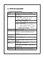
2. SPECIFICATIONS
2-1 General Specifications
Display 5 digits ( 0 to 99999 ) LCD display.
Circuit Exclusive one-chip design microprocessor
LSI circuit.
Measurement
Stroboscope
Unit : FPM ( rotation per minute ).
build in external trigger input.
Laser Photo Tachometer
Unit : RPM ( rotation per minute ).
Contact Tachometer
Unit : RPM ( rotation per minute ).
Surface speed ( ft/min., m/min )
* It should cooperate with optional
contact probe ( TA-35 ).
Sampling Time Approx. 1 second.
Calibration Crystal time base and microprocessor
circuit, no external calibration process
required.
Operating 0 to 50 ( 32 to 122 )℃℉
Temperature
Operating Less than 80% R.H.
Humidity
Power Supply AC( 100V to 240V ) to DC 9V ( 3A )
adapter.
Power
Stroboscope ( 3600 FPM ) :
Consumption DC 2.4 A.
Laser photo Tachometer ( 3600 RPM ) :
DC 50 mA.
Weight 1 Kg ( 2.2 LB ).
Dimensions 21 cmx12 cmx12 cm (8.3"x4.8"x4.8").
2

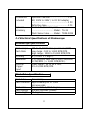
Accessories Operation manual..........................
.
1 PC.
Included AC( 100V to 240V ) to DC 9V adapter
.....................................................1 PC.
Reflective tape...............................1 PC.
Optional Contact Tachometer probe
Accessory ................................Model : TA-35
Flash Xenon tube.......Model : TBXE-2289
2-2 Electrical Specifications of Stroboscope
Stroboscope Specification
Stroboscopic 100 to 15,000 flashes per minute (FPM).
Flash Rate Low range : 100 to 1,000 RPM/FPM.
High range : 1000 to 15,000 RPM/FPM.
Accuracy ± ( 0.05% + 1 digit ).
Resolution 0.1 FPM/RPM (less than 1,000 FPM/RPM)
1 FPM/RPM ( > 1,000 FPM/RPM ).
External Input signal : 5V to 30 V rms,
Trigger 5 to 15,000 RPM/FPM.
Input
Flash Tube Specification
Flash tube Xenon lamp.
Flash Duration Approximately 60 to 1,000
microseconds.
Flash color Xenon white 6,500 K degree.
Flash energy 4 Watts-seconds (joules).
Beam Angle 80 degrees.
3

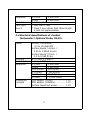
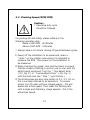
Flash tube It is required to change the flash tube
replacement when the instrument start to flash
irregularly at speeds of 3600 RPM/FPM
or more.
Flash tube with plug and socket, easy to
make the replacement.
Operating duty For prolong life and safety, please
Cycle adhere to the following operation duty
cycle: < 2000 RPM - 2 hours
2000 to 3600 RPM - one hour
3601 to 8000 RPM - 30 minutes
> 8000 RPM - 10 minutes.
* 10 min. cooling off period between cycles.
2-3 Electrical Specifications of Laser Photo
Tachometer
Range 10 to 99,999 RPM
Accuracy ± ( 0.05% + 1 digit ).
Sampling Time 1 sec. ( 60 RPM ).
Photo 50 - 2,000 mm typically.
Tachometer
* Spec. of detecting distance are that
detecting
under the size of reflecting tape is 10
distance
mm square & the measuring RPM
value is 1,800 PPM. The max. & min.
detecting distance may change under
different environment, different
reflecting tape or the measuring RPM
beyond 1800 PRM.
4

Resolution 0.1 RPM < 1,000 RPM
1 RPM 1,000 RPM≧
Time base Quartz crystal
Laser light * Less than 1 mW.
source * Class 2 laser diode. Red. Wave length
is 645 nm approximately.
2-4 Electrical Specifications of Contact
Tachometer ( Optional Probe, TA-35 )
Range
Contact Tachometer :
0.5 to 19,999 RPM
Surface Speed ( m/min. ) :
0.05 to 1,999.9 m/min.
Surface Speed ( ft/min. ) :
0.2 to 6,560 ft/min.
Accuracy ± ( 0.05% + 1 digit ).
Sampling Time 1 sec. ( 6 RPM ).
Resolution 0.1 RPM < 1,000 RPM
1 RPM 1,000 RPM≧
0.01 m/min. < 100 m/min.
0.1 m/min. 100 m/min.≧
0.1 ft/min. < 1000 ft/min.
1 ft/min. 1,000 ft/min.≧
Accessories RPM adapter (CONE)..................
.
1 PC.
Included RPM adapter (FUNNEL)............... 1 PC.
Surface speed test wheel............
.
1 PC.
5

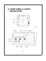
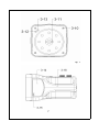
4. FRONT PANEL & LAYOUT
DESCRIPTION
Fig. 1
6

Fig. 1
7

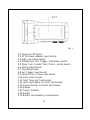
Fig. 1
3-1 Power On/Off Switch
3-2 DC 9V Power Adapter Input Socket
3-3 High, Low Range Switch
3-4 Stroboscope, Ext. Trigger, Tachometer Switch
3-5 Photo Tach, Contact Tach, ft/min.. m/min Switch
3-6 Coarse Adjust Knob
3-7 Fine Adjust Knob
3-8 Ext. Trigger Input Socket
3-9 Contact Tach. Probe Input Socket
3-10 Front Cover Screws
3-11 Flash Tube and Tube Socket
3-12 Laser Light Beam for Photo Tachometer
3-13 Sensing Sensor for Photo Tachometer
3-14 Display
3-15 Target Indicator
3-16 Handle
3-17 Battery Cover/Battery Compartment
8

4. POWER SUPPLY CONSIDERATION
1)The instrument is shipped along with an ACV ( 100V to
240V ) to DC 9V ( 3A ) adapter.
2)When operate the instrument, it should insert the
DCV output plug of DC adapter into the " DC 9V Power
Adapter Input Socket " ( 3-2, Fig. 1 ). Connect the
ACV input plug of DC adapter into the a properly
110V AC, 220V AC or 240V AC outlet.
Battery operation
The instrument also can operate by
batteries ( UM1/D type X 4 PCs ).
Due to high power consumption ( short
battery life ) for the Stroboscope function,
we do not recommend user operate the
STROBOSCOPE function via batteries.
However for the Tachometer function, as
the power consumption is lower, so if
user intend to use the batteries to operate
the TACHOMETER function, it is
convenient.
9

5. STROBOSCOPE MEASURING
PROCEDURES
Caution :
* Do not use fin
g
ers or any
tool to touch the FLASH
T
UBE.
* Risk of electric shock !
5-1 Preparation
1)Connect the DCV output plug of DC adapter into the
" DC 9V Power Adapter Input Socket " ( 3-2, Fig. 1 )
Connect the ACV input plug of DC adapter into the a
properly 110V AC, 220V AC or 240V AC outlet.
Caution :
* The power plug should be
connected to the correct AC
power supply.
2)Turn the power switch to " Power On/Off Switch "
( 3-1, Fig. 1 ) to the " On " position.
3)Select the " Stroboscope, Ext. Trigger, Tachometer
Switch " ( 3-4, Fig. 1 ) to the " Stroboscope " position.
4)Determine the range switch to "Low" or "High" position.
10

5-2 Checking Speed (RPM/FPM)
Caution :
* Operating duty cycle
should be followed.
For prolong life and safety, please adhere to the
following operation duty :
Below 2,000 RPM - 30 Minutes.
Above 2,000 RPM - 5 Minutes.
* Always allow a 10 minute cooling off period between cycles.
1)Power off the installation to be measured, make a
" mark " on the rotation area where it is intended to
measure the RPM. Then power on the installation to
be measured.
2)When checking the speed, care must be taken to ensure
that the strobe is flashing in unison (one to one) with the
object being monitored. Turn the " Fine Adjust Knob "
( 3-7, Fig. 1 ) or " Coarse Adjust Knob " ( 3-6, Fig. 1 )
until the mark look like " Stop " ( synchronize ).
3)The Stroboscope will also stop motion at 2:1, 3:1, 4:1 et.,
this is normally referred to as harmonics. To ensure
unison, turn the dial until two images appear - this will
double the actual speed. Then lower the flashing rate
until a single and stationary image appears - this is the
actual true speed.
11

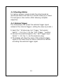
5-3 Checking Motion
For motion analysis, simply locate the actual speed as
mentioned above and then turn the dial slowly up or down.
This will give a slow motion effect allowing complete
inspection.
5-4 External trigger
The stroboscope can accept the external trigger signal
instead of the internal trigger ( setting the value by knobs ).
1)Select the " Stroboscope, Ext. Trigger, Tachometer
Switch " ( 3-4, Fig. 1 ) to the " Ext. Trigger " position.
2)Connect the external signal to the " Ext. Trigger Input
Socket " ( 3-8, Fig. 1 ) via the earphone plug.
3)The display will show the value of the external trigger
signal in the same time the Xenon tube will be flashed
according the external trigger signal.
12

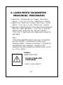
6. LASER PHOTO TACHOMETER
MEASURING PROCEDURES
1)Select the " Stroboscope, Ext. Trigger, Tachometer
Switch " ( 3-4, Fig. 1 ) to the " Tachometer " position.
2)Select The " Photo Tach, Contact Tach, ft/min.. m/min
Switch " ( 3-5, Fig. 1 ) to the " Photo Tach " position.
3)Adhesive a reflecting mark to the object being measured.
Align the " Laser light beam " ( 3-12, Fig. 1 ) with the
applied target. Verify that the " Monitor Indicator "
( 3-15, Fig. 1 ) lights when the target pass through the
light beam.
Note :
If the measured RPM values is very low ( for example
less than 50 RPM ), recommend to attach more "
Reflecting Marks " average to the object. It will get the
real RPM with high resolution, precisely & fast
sampling time when divided the reading values by the
no. of the " Marks ".
Caution :
LASER RADIATION -
DO NOT STARE INTO
LASER BEAM
* Class II laser products.
13

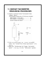
7. CONTACT TACHOMETER
MEASURING PROCEDURES
1)Prepare a optional Contact Tachometer Probe
" Model : TA-35 ".
The standard accessories of TA-35 are included :
RPM adapter ( Cone type )...................
a
RPM adapter ( Funnel type )..................
b
Surface speed test wheel......................
.
c
2)Insert the output plug of the " Contact Tachometer
Probe " into " Contact Tach. Probe Input Socket " ( 3-9,
Fig. 1 )
3)Select the " Stroboscope, Ext. Trigger, Tachometer
Switch " ( 3-4, Fig. 1 ) to the " Tachometer " position.
14

RPM measurement
4)Select The " Photo Tach, Contact Tach, ft/min., m/min
Switch " ( 3-5, Fig. 1 ) to the " Contact Tach " position.
5)Pressing the " RPM Adapter " lightly against the
center hole on the hole of the measured rotating axis.
Note :
Making the contact RPM measurement due to
different kind measured rotating axis, it may
changed the rubber for RPM adapter from " Cone "
type to " Funnel " type ( Refer page 14 ).
Surface Speed Measurement
1)Select The " Photo Tach, Contact Tach, ft/min., m/min
Switch " ( 3-5, Fig. 1 ) to the " m/min. " or " ft/min. "
position.
2)Change the " RPM Adapter " instead of the " Surface
Speed Test Wheel " ( Refer page 14 ).
3)Simply attaching the surface speed test wheel to the
detector.
15

8. FLASH TUBE REPLACEMENT
The flash tube requires changing when the instrument start
to flash erratically at speeds of 3600 RPM/FPM or more.
Caution :
* Change of the Flash Tube
should only be done by a
qualified technician. As the
instrument contains no user
serviceable parts.
* Before replace the tube, should
power off the meter, and wait
at least 10 minutes until the
circuit be discharged,
1)Loss the four " Front Cover Screws " ( 3-10, Fig. 1 ) and
take away the front end protection cover.
2)There is a plug and the socket for connecting the
the tube with the main instrument.
Take away the tube and replace the new unit.
3)Install the front end protection cover and fix the four
Front Cover Screws " ( 3-10, Fig. 1 ) again
16
Page is loading ...
-
 1
1
-
 2
2
-
 3
3
-
 4
4
-
 5
5
-
 6
6
-
 7
7
-
 8
8
-
 9
9
-
 10
10
-
 11
11
-
 12
12
-
 13
13
-
 14
14
-
 15
15
-
 16
16
-
 17
17
-
 18
18
-
 19
19
-
 20
20
-
 21
21


Lutron Electronics DT-2289 Operating instructions
- Category
- Measuring, testing & control
- Type
- Operating instructions
Ask a question and I''ll find the answer in the document
Finding information in a document is now easier with AI
Related papers
-
 Lutron Electronics DT-2249A Operating instructions
-
 Lutron Electronics DT-2239A Operating instructions
-
 Lutron Electronics DT-2234BL Operating instructions
-
 Lutron Electronics vt-8204 Operating instructions
-
 Lutron Electronics vt-8204 Operating instructions
-
 Lutron Electronics vt-8204 Operating instructions
-
 Lutron Electronics DM-9030 User manual
-
 Lutron Electronics DT-2230 Operating instructions
-
 Lutron Electronics DM-9131 Operating instructions


Other documents
-
Prexiso P20 User manual
-
Aktakom ATE-6020 User manual
-
Monarch Nova-Strobe dbx User manual
-
Omega HHT31R and HHT32R Owner's manual
-
Nidec ST-5000 Operating instructions
-
-
-
 Nidec-Shimpo PT-110 Operation Manuals
-
Velleman DTO2234 User manual
-
Monarch PALM STROBE x Pocket-Size User manual
