Page is loading ...

CAT III 1000V, true rms, L/C/R
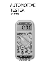
AUTOMOTIVE
TESTER
Model : DM-9131
Your purchase of this
AUTOMOTIVE TEST
marks a step forward
for you into the field of
precision measurement.
Although this
Automotive test is a
complex and delicate
instrument, its durable
structure will allow
many years of use if
proper operating
techniques are
developed. Please read
the following
instructions carefully
and always keep this
manual within easy
reach.
OPERATION MANUAL

TABLE OF CONTENTS
1.
FEATURES....................................................................................................
1
2.
SPECIFICATIONS...................................................................................
2
2-1 General Specifications...........................................................................
2
2-2 Electrical Specifications..........................................................................
3
3.
FRONT PANEL DESCRIPTION...................................................................
7
4. PRECAUTIONS & PREPARATIONS FOR
MEASUREMENT..........................................................................................
8
5.
MEASURING PROCEDURE..........................................................................
9
5-1 Symbols & Units of Display ...................................................................
9
5-2 DC voltage, AC voltage true rms Measurement ...........................
10
5-3 Resistance Measurement.........................................................................
10
5-4 DC current, AC current true rms Measurement ..................................
11
5-5 Continuity Check ...................................................................................
12
5-6 Diode Test ..............................................................................................
12
5-7 Capacitance Measurement.......................................................................
14
5-8 Inductance Measurement.........................................................................
14
5-9 L/C Calibration........................................................................................
15
5-10 Frequency Measurement.......................................................................
15
5-11 Temperature Measurement....................................................................
16
5-12 Tach. Measurement …………………………………………………………
16
5-13 "DWELL ANGLE" Measurement 17
5-14 Point check…………………………………………………………………..
19
5-15 Optional Adapter…………………………………………………………
19
5-16 Relative Measurement...........................................................................
20
5-17 Data Hold Operation..............................................................................
20
5-18 LCD Backlight ON/OFF........................................................................
20
5-19 Max/Min. value record...........................................................................
21
5-20 RS232 Computer Interface.......................................................................
21

6.
ADVANCED SETTING.................................................................................
23
8-3 Set Auto power OFF management..................................................................
24
8-4 Set beeper sound ON/OFF..................................................................
25
8-6 Set clock time(Year/Month/Date,Hour/Minute/Second)............................
26
8-7 Set Change the Temp.
℃
,
℉
unit...........................................................
26
7.
MAINTENANCE...........................................................................................
26
7-1 Replacement of Battery...........................................................................
26
7-2 Cleaning...................................................................................................
26
7-3 Replacement of Fuse...............................................................................
27
8.
OPTIONAL ACCESSORIES & ADAPTERS .................................................
28
9.
THE ADDRESS OF AFTER SERVICE CENTER..........................................
29

1. FEATURES
* Meet IEC 1010 CAT III 1000 V safety requirement.
* LCD with green light backligh, easy reading.
* 6000 counts A/D, high resolution.
* Multi function measurement. DCV, ACV, DCA, ACA,
Resistance, Capacitance, Inductance, Frequency,
Temperature, Diode, Continuity beeper, TACH,
DWELL, POINT, 2000A Clamp
* Max. & Min. measurement value with recall.
* Relative, Data hold.
*
Auto range with manual range selection.
*
Temperature measurement posibility.
*
V/A/Hz button, when execute the ACV, ACA function also
can measure the frequency of signal.
*
Both 10 A, 6A current are build fuse for safety
consideration.
* 10 M ohm impedance for voltage circuit.
* Operates from 9 V ( 006P, MIN1604 ) batteries.
* Built-in overload protection for most ranges.
* Photo couple RS 232 computer serial interface.
* Uses durable, long-lasting components, enclosed in
strong, light weight ABS-plastic housing.
* Full line optional adapters : Clamp adapter,
Tachometer adapter, Pressure adapter, Humidity
Adapter, Sound level adapter, Anemometer adapter,
Light adapter, EMF adapter.
1

2. SPECIFICATIONS
2-1 General Specifications
Display 60 mm x 39 mm large LCD display
Measurement DCV, ACV, DCA, ACA, Resistance,Diode,
Continuity beeper,Capacitance,
Inductance, Frequency, Temperature.
A/D counts no. 6000 counts.
Range selection Auto range with manual range selecting.
Special function Relative measurement
Data hold
To freeze the display reading on the
LCD display.
Power On/Off Auto power of or manual power off.
management @ Details please refer page 7
Memory recall Records Maximum & Minimum readings
with recall.
Relative To offset the measurement value.
measurement
V/A/Hz button
When execute the voltage or current
function also can measure the frequency
of signal.
Data output RS 232 PC serial interface, photo couple.
Polarity Automatic Switching, " - " indicates
negative polarity.
Zero adjustment Automatic.
Sampling time Approx. 0.5 to 1 second.
Operating
0 ℃ to 50 ℃ (32 ℉ to 122 ℉),
Temp. & humidity Max. 80% RH.
Power supply 9 V ( 006P, MIN1604 )
DC 9V adapter input
*AC/DC Power adapter is optional.
Power consumption Approx. DC 7.0 mA.
Weight 378 g/0.83 LB ( w.o battery ).
Dimension 190 x 88 x 40 mm ( 7.5 x 3.5 x 1.6 inch ).
2

Accessories
Red and Black Test Leads…………………
1 Set
Included
Instruction Manual.....................................
1 PC
Optional Full line adapters :
accessories ACA/DCA current adapter,
Tachometer adapter,
Humidity adapter, Pressure adapter,
Light adapter, EMF adapter,
Sound level adapter,
High voltage probe.
AC to DC 9V Adaptre…………………... AP-9VA
Holster……………………………………... HS-03
Type K Temperature probe.....................
TP-11
Soft carryinfg case....................................
CA-05A
RS232 cable to D-Sub 9 connector..............................................
UPCB-06
RS232 cable to USB connector........................
UPCB-11
RPM inductive pick up sensor………….. IP-09
Data Acquisition software……….. SW-U801-WIN
SW-E802
2-2 Electrical Specifications (23±5
℃
℃℃
℃
)
DC Voltage
Range 600.0 mV /6 V/60 V/600 V /1000 V
Resolution 0.1 mV /0.001V /0.01V /0.1V/1 V
Accuracy ± ( 0.5% + 2d ) 600 mV
± ( 0.8% + 1d ) 6 V, 60 V, 600 V, 1000 V
Input impedance 10 M ohm.
Over load 600 mV range ± 380 DCV, 380 ACV
protection other ranges ±1000 DCV, 1000 ACV
AC Voltage ( True RMS )
Range 600.0 mV /6 V/60 V/600 V /1000 V
Resolution 0.1 mV /0.001V /0.01V /0.1V/1 V
Accuracy ± ( 1% + 2d )
* Spec. are tested under 50/60 Hz.
Input impedance 10 M ohm.
Over load 600 mV range ± 380 DCV, 380 ACV
protection other ranges ±1000 DCV, 1000 ACV
3

DC Current, AC Current ( True RMS )
DC Current, AC Current ( True RMS )DC Current, AC Current ( True RMS )
DC Current, AC Current ( True RMS )
Range 10 A / 6 A
Resolution 0.01 A / 0.001A
Accuracy DCA ACA
6 A ± (1.5%+2d) ± (1.5%+2d)
10 A ± ( 1.5 % + 2d ) ± ( 1.5 % + 2d )
* ACA spec. are tested under 50/60 Hz.
Over load 10A fuse.
protection
Diode ( Forward voltage, VF )
Diode ( Forward voltage, VF )Diode ( Forward voltage, VF )
Diode ( Forward voltage, VF )
Range 2.9 V DC.
Accuracy ± ( 0.5% + 2d )
Capacitance
CapacitanceCapacitance
Capacitance
Auto Range 600 pF/6 nF/60 nF/600 nF/6 uF/60 uF/100 uF/600 uF
Resolution
0.1 pF/0.001 nF/0.01nF/0.1 nF/0.001 uF/0.01 uF/0.1 uF/1uF
600 pF ±( 2.5% + 5d )
Accuracy 6 nF/60 nF/600 nF/6 uF/60 uF ±( 1.5% + 5d )
100uF/600 uF ±( 2.5% + 5d )
Test frequency
100Hz /1KHz /10KHz (Auto frequency configuration)
Remark Discharge capacitor before testing.
Over load protection
±30 DCV, 30 ACV.
Inductance
InductanceInductance
Inductance
Auto Range 600 uH/6 mH/60 mH/600 mH/6 H/60 H/100 H
Resolution 0.1uH/0.001mH/0.01 mH/0.1 mH/0.001 H/0.01 H/0.1 H
Test frequency
100Hz /1KHz /10KHz (Auto frequency configuration)
600 uH ±( 5% + 5d )
Accuracy 6 mH/60 mH/600 mH/6 H ±( 1.5% + 5d )
60 H /100 H ±( 2.5% + 5d )
Over load protection
±30 DCV, 30 ACV.
4

Frequency
FrequencyFrequency
Frequency
Range 600 Hz/6 KHz/60 KHz/600 KHz/6 MHz/20 MHz
Resolution
0.1 Hz/0.001 KHz/0.01 KHz/0.1 KHz/0.001 MHz/0.01 MHz
Accuracy ±( 0.5% + 2d )
Sensitivity Min. 1 V rms, Max. 5 V rms.
OHMS
Range 600 Ω/6 KΩ/60 KΩ/600 KΩ/6 MΩ/60 MΩ
Resolution 0.1Ω/0.001 KΩ/0.01 KΩ/0.1 KΩ/0.001 MΩ/0.01 MΩ
Accuracy 600 ohm : ±( 1 % + 2d )
6K/60K/600K/6 M : ±( 1.5 % + 2d )
60 M : ±( 3 % + 5d )
Over load ±350 DCV, 350 ACV.
protection
Continuity Beeper
Beeper will sound if measured resistance less than 20 ohm.
Max. & Min. Measurement
During the operation can memorize the maximum and the
minimum measurement value.
Temperature
Auto Range Resolution Accuracy
-100.0 ℃ to 199.9 ℃ 0.1 ℃ ±( 1% + 1 ℃ )
200 ℃ to 1000 ℃ 1 ℃
-148.0 ℉ to 391.9 ℉ 0.1 ℉ ±( 1% + 2 ℉ )
392 ℉ to 1832 ℉ 1 ℉
Temp. probe The temperature probe ( TP-11 ) is the
optional accessory.
5

TACH
Range 500 -30000RPM
Resolution
10RPM
Accuracy ±( 1% + 2d )
OVERLOAD 24V DC/AC RMS ( within 1 min )
PROTECTION
DWELL
CYLINDER 3 CYL 4CYL 5CYL 6CYL 8CYL DUTY CYCLE
Range 0-120° 0-90° 0-72° 0-60° 0-45° 0-100%
Resolution
0.1°
0.1° 0.1° 0.1° 0.1° 0.1%
Accuracy ±( 1 % + 2d )
Over load ±200 DC/AC RMS (within 15 sec)
protection
Point
Range
≧ 0.2V <0.2V
ACCURACY
60V DC chang good ±( 1.2% + 2d )
Resolution 0.01V DC
Accuracy ±( 1.2% + 2d )
OPTIONAL ADAPTER
Range MAX. DISPLAY PER DIGIT ACCURACY
CAPACITY EQUAL
2000A 2000 1mV DC/AC ±( 1.2% + 2d )
IR TEMP 600.0 0.1mV DC
Remark :
* Spec. tested under the environment RF Field Strength
less than 3 V/M & frequency less than the 30 MHz only.
6

3. FRONT PANEL DESCRIPTION
Fig. 1
3-1 Display 3-10 Function rotary switch
3-2 MAX/MIN ( ▼ ) button
3-11 Temp./ohm/V/Cap. input terminal
3-3 TIME (SET) button 3-12 COM input terminal
3-4 REL(Backlight) button 3-13 DWELL / TACH input terminal
3-5 HOLD ( ▲ ) button
3-14 10A input terminal
3-6 RANGE button 3-15 Battery compartment/Cover
3-7 VAHz button 3-16 RS232 terminal
3-8 ENTER button 3-17 DC 9V Power Adapter Input Socket
3-9 AC/DC button
7

4. PRECAUTIONS & PREPARATIONS FOR
MEASUREMENT
1) Ensure that the DC 9 V ( 006P, MIN1604 ) batteries are connected
with the right polarity and placed in the battery compartment
correctly.
2) Place the Red & Black Test Leads into the proper input
terminal before making measurement.
3) Remove either of the test leads from the circuit when
changing the measurement range.
4) Except operate the " Data Hold " function, it should
cancel the " Data Hold " function, otherwise the display
reading will freeze permanently.
5) Do not exceed the maximum rated voltage and current to
the input terminal.
6) Always switching the " Function Rotary Switch " to the
" Off " position when the instrument is not operation.
7) Remove the battery if the instrument is not to be used in
a long period of time.
8) For safety consideration, when change the new test
leads, it should use the replace test leads that already
approval of " CATIII-1000 V " at least.
9) Power On/Off management :
a. When not use the meter, should rotate the " Function rotary
switch " ( 3-10, Fig. 1 ) to the " OFF " position.
b. During the measurement, after 10 minutes the meter
will auto power off. If intend to power on again, it
should rotate the " Function switch " to " OFF "
position then set to the new desiring function position.
c. Disabling auto power off ( not auto power off )
Press the " TIME button " ( 3-2, Fig. 1 ) into
the setting mode,the Poff set " no "
auto power off function can be lifted.
8

5. MEASURING PROCEDURE
5-1 Symbols & units of display
Symbols Descriptions
Units
AUTO
Appears when selecting " Automatic range " mode.
MANU
Appears when selecting " Manual range " mode.
DC
Appears when selecting DC mode.
( DC voltage or DC current )
AC
Appears when selecting AC mode.
( AC voltage or AC current )
HOLD
Appears when the " Data hold " function is operated.
REL
Appears when the " Relative " function is operated.
Max
Appears when " Max and Min. value record "
Min
function is operated.
Battery voltage is already under the low condition.
Appears when the " Continuity beeper " is operated.
mV, V
Units for" voltage " measurements.
Ω,KΩ,MΩ
Units for " resistance" measurements.
A
Units for " Current " measurement.
uH,mH,H
Units for " Inductance " measurement.
pF,nF,uF,
Units for " Capacitance " measurement.
Hz,KHz,MHz
Units for " Frequency " measurement.
Appears when the " Diode " function is operated.
–
Appears when measuring a DCV or DCA value
is negative.
℃
℃℃
℃ ℉
℉℉
℉
Units for " Temperature " measurement.
– – – –
Over range indicator
RPM
Units for " TACH " measurements.
Appears when selecting " DWELL " mode.
P
%(duty cycle),indicate how high a duty cycle.
Degree
Units for " DWELL " measurement.
9

5-2 DC Voltage, AC voltage ture rms Measurement
1) Connect BLACK test lead into " COM " terminal ( 3-12,
Fig. 1 ).
2) Connect RED test lead into " V " terminal ( 3-11, Fig. 1 ).
3) Select the " Function rotary switch " ( 3-10, Fig. 1 ) to
the " V " position.
4) Push the " AC/DC button " ( 3-9, Fig. 1 ) to select the
" ACV " or " DCV " measurement,
5) When LCD show the " AUTO " marker, the meter is
under the " auto range " mode. Meter will select the
suitable measurement range automatically.
6) Under the operation of " auto range " mode, push the
" Range button " ( 3-6 Fig. 1 ) once will execute the
" Manual Range " mode and hold the range, the LCD will
show the " MANU " marker.
Under the manual range operation, push the " Range
button " ( 3-6 Fig. 1 ) > 2 seconds, will return to auto
range operation.
Remark :
During the measurement, if push the " VAHz button " ( 3-7
Fig. 1 ) once, until the LCD show the " Hz " marker and the
display will show the frequency value of the measurement signal.
5-3 Resistance Measurement
1) Connect BLACK test lead into " COM " terminal ( 3-12,
Fig. 1 ).
2) Connect RED test lead into " Ω " terminal ( 3-11, Fig. 1 ).
3) Select the " Function rotary switch " ( 3-10, Fig. 1 ) to
the " Ω " position.
4) When LCD show the " AUTO " marker, the meter is
under the " auto range " mode. Meter will select the
suitable measurement range automatically.
10

5) Under the operation of " auto range " mode, push the
" Range button " ( 3-6 Fig. 1 ) will execute the " Manual
Range " mode and hold the range, the LCD will show
the " MANU " marker.
Under the manual range operation, push the " Range
button " ( 3-6 Fig. 1 ) > 2 seconds, will return to auto
range operation.
5-4 DC Current, AC Current ture rms Measurement
A : 10A range, 6A range.
1) Connect BLACK test lead into " COM " terminal ( 3-12, Fig. 1 ).
2) For the " 10 A " current measurement, connect RED
test lead into " A " terminal ( 3-14, Fig. 1 ).
Open the circuit in which current is to be
measured. Now securely connect test leads in series
with the load in which the current is be measured.
3) For the " 10 A " measurement ( 6A,10A ), select the " Function rotary
switch " ( 3-10, Fig. 1 ) to " A " position.
4) Push the " AC/DC button " ( 3-9, Fig. 1 ) to select the
" ACA " or " DCA " measurement,
5) When LCD show the " AUTO " marker, the meter is
under the " auto range " mode. Meter will select the
suitable measurement range automatically.
11

6) Under the operation of " auto range " mode, push the
" Range button " ( 3-6 Fig. 1 ) once will execute the
" Manual Range " mode and hold the range, the LCD will
show the " MANU " marker.
Under the manual range operation, push the " Range
button " ( 3-6 Fig. 1 ) > 2 seconds, will return to auto
range operation.
Remark :
During the measurement, if push the " V/A/Hz button " ( 3-7
Fig. 1 ) once, until the LCD show the " Hz " marker and the
display will show the frequency value of the measuement signal.
5-5 Continuity Check
1) Connect BLACK test lead into " COM " terminal.
2)
Connect RED test lead into " Ω " terminal.
3) Select the " Function rotary switch " ( 3-10, Fig. 1 ) to
the " " position.
4) The LCD display will show the " " marker.
5) when the resistance value is less than 20 ohm, the beeper
sound will be generated.
5-6 Diode Test
1) Connect BLACK test lead into " COM " terminal.
2) Connect RED test lead into " V " terminal.
3) Select the " Function rotary switch " ( 3-10, Fig. 1 ) to
the " " position.
The LCD display will show the " " marker.
4) a. When connected with polarity as shown in Fig. 2, a
forward current flow is established and the approx.
Diode Forward Voltage (VF) value in volt will appears
on the display reading. If the diode under test is
defective, " 0.000 " or near " 0.000 " value ( short circuit )
" – – – – " ( open circuit ) will be displayed.
12

Fig. 2
Fig. 2
b. When connected as shown in Fig. 3, a reverse check on
the diode is made. If the diode under test is good, "– – – –"
will be displayed. If the diode under test is defective,
" 0.000 " or other numbers will be displayed. Proper diode
testing should include both steps a. and b. above.
Fig. 3
Fig.3
13

5-7 Capacitance Measurement
1) Select the " Function rotary switch " ( 3-10, Fig. 1 ) to
the " " position.
2) Connect the tested capacitor to " Input terminals " directly.
*
If the measured capacity existing the polarity, then
should connect the " +
++
+ " polarity of the measured
capacitor to the " " terminal ( 3-11, Fig. 1 ),
connect the " -
--
- " polarity of the measured
capacitor to the " COM " terminal ( 3-12, Fig. 1 ),
*
Full discharge the measured capacitor before the
make the measurement.
3) When LCD show the " AUTO " marker, the meter is
under the " auto range " mode. Meter will select the
suitable measurement range automatically.
4)
Capacitance measurement mode, no manual functions,
" Range button " ( 3-6 Fig. 1 ) is invalid.
5-8 Inductance Measurement
1) Connect BLACK test lead into " COM " terminal ( 3-12,
Fig. 1 ).
2) Connect RED test lead into " " terminal ( 3-11, Fig. 1 ).
3) Select the " Function rotary switch " ( 3-10, Fig. 1 ) to
the " " position.
4) When LCD show the " AUTO " marker, the meter is
under the " auto range " mode. Meter will select the
suitable measurement range automatically.
5) Inductance measurement mode, no manual functions,
" Range button " ( 3-6 Fig. 1 ) is invalid.
14

5-9 L/C Calibration
In order to improve the accuracy of a high / low impedance,
Recommend doing open / short calibration
Before measurement.
Open / short calibration procedure:
1)
Simultaneously push " AC / DC " and " REL " button more
to start open / short calibration,The display will show "OPEn",
than 2 seconds, then push "enter" key once,LCD will display 30,
and the countdown to zero,
2)
The display will show " Short ", set the input of a short circuit,
then pushthe "enter" key once,LCD will display 30, and the
countdown to zero, then the calibration data is saved to the
EEPROM, complete the calibration.
5-10 Frequency Measurement
1) Connect BLACK test lead into " COM " terminal ( 3-12, Fig. 1 ).
2) Connect RED test lead into " Hz " terminal ( 3-11, Fig. 1 ).
3) Select the " Function rotary switch " ( 3-10, Fig. 1 ) to the
" Hz " position, LCD will show the " Hz " marker.
4) When LCD show the " AUTO " marker, the meter is
under the " auto range " mode. Meter will select the
suitable measurement range automatically.
5) Under the operation of " auto range " mode, push the
" Range button " ( 3-6 Fig. 1 ) once will execute the
" Manual Range " mode and hold the range, the LCD will
show the " MANU " marker.
Under the manual range operation, push the " Range
button " ( 3-6 Fig. 1 ) > 2 seconds, will return to auto
range operation.
15

5-11 Temperature Measurement
1) Plug in the optional " Type K Temperature probe, TP-11 "
into the input terminals, " TEMP input terminal " ( 3-11, Fig. 1 )
and the " COM input terminal " ( 3-12, Fig. 1 )
2) Select the " Function rotary switch " ( 3-10, Fig. 1 ) to
the " TEMP " position.
3) Temperature measurement mode, no manual functions,
" Range button " ( 3-6 Fig. 1 ) is invalid.
5-12 Tach. Measurement
1) Tach. Measurement is with INDUCTIVE PICKUP SENSOR,
IP-07 or IP-08 ( Optional ).
2) Connect above INDUCTIVE PICKUP sensor black test into
" COM " terminal ( 3-12, Fig. 1 ). and RED test lead into
" TACH " terminal ( 3-13, Fig. 1 ).
3) Select the " Function rotary switch " ( 3-10, Fig. 1 ) to
the " TACH. " position.
4) Connect the TACH. INDUCTIVE PICK UP SENSOR to
the high tension wire of No. 1 SPARK PLUG (or No. 2,
No. 3... SPARK PLUG), ref. Fig. 4, then the display
will show RPM reading .
NOTE:
a. RPM (TACH) used the "Secondary Tech"
measuring method, no matter what cylinder is
b. If the display reading is unstable, it may be caused
by environment interference. Please readjust the
position of RPM INDUCTIVE PICK UP SENSOR
or changed the direction of INDUCTIVE CLAMPS.
16

Fig. 4
5-13 "DWELL ANGLE" Measurement
1) Select the " Function rotary Switch " (3-10, Fig.1 ) to the
" DWELL" position.
2) Determine the % (duty cycle), 3 cyl, 4cyl, 5 cyl, 6 cyl .
by push the " Range Button " (3-6, Fig.1 ).
2) Connect black test lead into " COM" terminal ( 3-12, Fig. 1)
and red test lead into "DWELL" terminal ( 3-13, Fig. 1 ).
3) Connect red test probe into " BREAKER POINTS " or
" -
--
- " terminal of IGNITION COIL.
Connect black test probe into " GROUND" or "-"
terminal of battery.
* The wire connection diagram please ref.( Fig. 5)
4) Crank engine, the display will show the DWELL ANGLE
of points.
17
/

