Monarch PALM STROBE x Pocket-Size User manual

Category
Camera flashes
Type
User manual

Monarch PALM STROBE x Pocket-Size is a compact, single-handed stroboscope that fits in the palm of your hand and allows you to accurately measure and adjust the speed of rotating or reciprocating machinery. With a flash rate range of 100 to 12,500 flashes per minute, it can freeze motion for detailed inspection or synchronization.

Monarch PALM STROBE x Pocket-Size is a compact, single-handed stroboscope that fits in the palm of your hand and allows you to accurately measure and adjust the speed of rotating or reciprocating machinery. With a flash rate range of 100 to 12,500 flashes per minute, it can freeze motion for detailed inspection or synchronization.

15 Columbia Drive
Amherst, NH 03031 USA
Phone: (603) 883-3390
Fax: (603) 886-3300
PALM STROBE x
Pocket-Size
Portable Stroboscope
MONARCH INSTRUMENT
Instruction Manual
Patented
Printed in the U.S.A.
Copyright 2009, Monarch Instrument, all rights reserved
1071-4205-112R
0109
www.64817.com
www.64817.com
www.64817.com
Safeguards and Precautions
1. Read and follow all instructions in this manual carefully, and retain
this manual for future reference.
2. Do not use this instrument in any manner inconsistent with these
operating instructions or under any conditions that exceed the
environmental specifications stated.
3. Use of this product may induce an epileptic seizure in persons
prone to this type of attack.
4. Objects viewed with this product may appear to be stationary
when in fact they are moving at high speeds. Always keep a safe
distance from moving machinery and do no touch the target.
5. There are lethal voltages present inside this product. Refer to
the section on Lamp Replacement before attempting to open this
product.
6. Do not allow liquids or metallic objects to enter the ventilation
holes on the stroboscope as this may cause permanent damage
and void the warranty.
7. This product contains Nickel Metal Hydride batteries which must
be disposed of in accordance with Federal, State and Local
Regulations. Do not incinerate. Batteries should be shipped to a
reclamation facility for recovery of the metal and plastic
components as the proper method of waste management. Refer
to section 7.3 of this manual, and contact your distributor for
appropriate product return procedures.
8. This instrument is not user serviceable. For technical assistance,
contact the sales organization from which you purchased the
product or Monarch Instrument directly.
In order to comply with EU Directive 2002/96/EC on Waste Electrical
and Electronic Equipment (WEEE): This product may contain material
which could be hazardous to human health and the environment. DO
NOT DISPOSE of this product as unsorted municipal waste. This product
needs to be RECYCLED in accordance with local regulations, contact
your local authorities for more information. This product may be returnable
to your distributor for recycling - contact the distributor for details.
Monarch Instrument’s Limited Warranty applies. See
www.monarchinstrument.com for details.
Warranty Registration and Extended Warranty coverage available online at
www.monarchinstrument.com.
Alan Woolfson, VP Engineering
Manufacturer (Amherst, NH) (Authorized Signature)
July 1
st
, 2007
As Manufacturer:
Monarch Instrument
Division of Monarch International Inc
15 Columbia Drive, Amherst NH 03031. USA
declares under Monarch’s sole responsibility that the product
to which this declaration relates is in conformity with the
following standards
and therefore conforms with the requirements of Council
Directive 89/336/EEC relating to electromagnetic compatibility.
The testing of this product was performed by Retlif Testing
Laboratories, NH, (Report No. R-3993N and R4702N-7)
and therefore conforms with the requirements of Council
Directive 73/23/EEC and 93/68/EEC relating to the low voltage
directive with amendments.
Palm Strobe X – Portable Battery Powered Stroboscope
EN61326:1997
Specifically: EN55022 Class B EN6100-4-2
EN6100-4-3 EN6100-4-4 EN6100-4-6
EN 61010 –1
Safety Requirements for Electrical Equipment for
Measurement, Control and Laboratory Use.
CE DECLARATION OF CONFORMIT
Y
1.0 SPECIFICATIONS ....................................................................................... 1
2.0 OVERVIEW ................................................................................................ 2
2.1 Display Panel .................................................................................... 3
3.0 PREPARATION FOR USE ........................................................................... 3
3.1 Power ................................................................................................ 3
3.2 Input / Output Connections ................................................................ 3
4.0 OPERATION ................................................................................................ 4
4.1 Internal Mode - Standard Strobe Operation ......................................... 4
4.2 External Input Mode ........................................................................... 5
4.3 Tach Mode (No Flash) - External Input Required ................................ 5
5.0 USING THE STROBOSCOPE TO MEASURE RPM .................................... 6
6.0 LAMP REPLACEMENT ............................................................................... 7
7.0 BATTERY PACK.......................................................................................... 8
7.1 Low Battery Indication ........................................................................ 9
7.2 Charging the Battery Pack ................................................................. 9
7.3 Battery Disposal ................................................................................ 9
8.0 OPTIONS AND ACCESSORIES ................................................................ 10
TABLE OF CONTENTS
TABLE OF CONTENTS
This page intentionally left blank.
www.64817.com
1
1.0 SPECIFICATIONS
Internal Mode:
Flash Range 100 - 12,500 FPM (Flashes per Minute)
Flash Rate Accuracy The greater of ±0.5 FPM or ±0.01% of reading
Flash Rate Resolution (Setting) 0.1 FPM
Display Update Rate Continuous
External/Tachometer Mode:
Flash Range and Display 5.0 to 12,500 FPM - External flash rates to 0 are acceptable
Tachometer Measurements 5 to 250,000 RPM - No flash
Accuracy The greater of ±0.1 FPM or ±0.01% of reading
Display Update Rate 1 second typical
Trigger to Flash Delay < 5 µsec
External Input 0 to 5 volt TTL Compatible (12V pk max)
1 µsec min pulse width, Positive edge triggered
Time Base Stable Crystal Oscillator
Display 6-digit alphanumeric backlit LCD display with 0.3 inch [7.62 mm] high digits
Indicators Low Battery, On Target Indicator, Locked On, External Mode, Tachometer
Mode, ÷2 ×2
Adjustment Four Quadrant Tuner Button with decade select for flash rate up or down,
multiply by 2 and divide by 2
Memory Saves eight programmable flash rates and last flash rate at power down
Output Pulse 350 µsec positive pulse, 5 Vdc typical
Power Removable 6 Vdc Rechargeable Battery Pack with Integral Electronics Charge
Control for rechargers (PSC-2U Recharger: 9 Vdc @ 500mA)
Light Power 150 mJ/Flash up to 3000 FPM, 7.9 Watts @ 6000 FPM
Flash Duration 10 - 30 microseconds typical
Run Time 2 hours at 1800 FPM and 1 hour at 6000 FPM typical with fully charged
batteries
Charge Time about 4 hours
Weight 1.2 lbs [544 g] including Battery Pack
Figure 1 Dimensions in Inches [mm]
8.0 OPTIONS AND ACCESSORIES
PSx Battery Additional NiMH blue Battery Pack (one is supplied with the Strobe)
SPSR-115/230 Self-Powered Sensor for TTL trigger input or Tachometer mode operation;
includes ROS-P optical sensor with 8 foot cable, 115/230 Vac Universal recharger
and 12 inches of reflective tape
PS Input Cable Pulse Input Cable, 6 foot [1.8 m], 1/8 inch [3.5 mm] stereo plug to male BNC
connector. Used with the SPSR Self-Powered Sensor.
PS Output Cable Pulse Output Cable, 6 foot [1.8 m], 1/8 inch [3.5 mm] mono plug to male BNC
connector. Used with Vibration Data Collectors.
PSC-2U Universal Recharger (Kit) for PSx Battery Pack – Universal 100 to 230 Vac
recharger with assorted adapter plugs
CC-9 Latching carrying case for PALM STROBE x with provision for accessories
PS Holster Holster carrying case for PALM STROBE x and spare Battery Pack that clips on
belt loop
L-1905 PALM STROBE x spare lamps (flashtubes), twin pack
10
www.64817.com
2.0 OVERVIEW
The PALM STROBE x is a sophisticated stroboscope with many features, yet remains simple to
operate. It is a pocket-size, lightweight, industrial strength, single-handed operation instrument that
fits in the palm of your hand. A four Quadrant Tuner Button adjusts the flash rate, and provides
multiply or divide by 2 functions. A large, bright, backlit, 6-digit alphanumeric LCD display shows
the flash rate and mode of operation. The Strobe can store and recall eight programmable flash rate
settings and the last used setting in non-volatile memory, so that the unit “remembers” all the flash
rates when the power is turned off.
The Strobe has a removable, rechargeable Battery Pack which provides up to 2 hours of continuous
use depending on the flash rate. This Battery Pack clips in and out with no tools required. An
optional second Battery Pack allows for longer operation in the field. A ¼-20 UNC thread bushing
on the underside of the Strobe allows for tripod mounting. The Strobe locks “ON” for hands free
operation.
The Input/Output phone jack will accept an external input up to the maximum FPM and can be used
with an external Self-Powered Sensor to measure RPM. The Input/Output phone jack will also
provide TTL output pulses for each flash.
2
Input/Output
Phone Jack
Battery
Charge
Indicator
Battery
Recharger
Socket
Figure 2 PALM STROBE x
Tuning Button
This product protected by U.S.A. Patents D492,805 and 6,945,666.
LCD Display
Removable
Battery Pack
Power Button
Mode Button
7.1 Low Battery Indication
When the batteries are low, the Low Battery icon ( ) is displayed. The Strobe may still be
used for a short time. When the battery charge is further depleted, the Strobe will stop flashing,
the Low Battery icon ( ) will be displayed, and then the Strobe will completely shut off.
When the Low Battery icon ( ) is displayed, the Battery Pack needs to be recharged (see
section 7.2).
NOTE: If the batteries are discharged you will not be able to run the unit. The unit may not
start at all, or the Low Battery icon ( ) may be displayed and then the Strobe will
shut off. Recharge the Battery Pack or replace it with a fully charged unit.
7.2 Charging the Battery Pack
The Battery Pack may be recharged at any time. You do not need to wait until the low battery
condition is indicated. The Battery Pack does not need to be in the Strobe for charging.
To charge the Battery Pack:
1. Make sure the Strobe is off or remove the Battery Pack from the Strobe.
2. Plug the recharger cable into the battery recharger socket on the Battery Pack (see Figure
2 for location).
3. Plug the recharger into an AC mains wall outlet.
NOTE: When using the Universal recharger, make sure the correct adapter plug
is inserted into the recharger before plugging the recharger into the wall
outlet.
CAUTION: Use of rechargers other than the one supplied (PSC-2U) may damage
the stroboscope and void the warranty.
The battery module contains circuitry to control the charge. The amber LED blinks steady to
indicate that the battery is being charged. The LED will turn solid amber as it nears complete
charge. Once the charge is completed, the LED turns solid green and the recharger will trickle
charge the battery. The Battery Pack may be used at this point.
NOTE: The total charge time is typically about 4-5 hours. The Battery Pack may be left on
trickle charge indefinitely.
The LED also indicates that charging has stopped due to a problem. The LED will blink 5, 6,
7, or 8 short red blinks and then one long green blink to indicate the following: 5 = over voltage,
6 = over current, 7 = too hot, and 8 = too cold.
7.3 Battery Disposal
Prior to disposing of the Battery Pack, the user must remove the Nickel Metal Hydride batteries.
To do this, remove the four screws on the under side of the Battery Pack and separate the case
halves, exposing the battery. Remove the cables from the battery and place tape over the
battery terminals to prevent them from shorting. The battery should be sent to a recycling
center or returned to the factory. The rest of the parts may now be disposed of.
9
www.64817.com
3
2.1 Display Panel
The display panel consists of a backlit, liquid crystal display with six alphanumeric digits
which indicate modes, flash rates, etc. (see Figure 3).
Other icons or messages in the display indicate the following:
Displayed when the battery is getting low. There is protection circuitry in the
unit that will prevent the battery from being over discharged or prevent the unit
from being operated with a low battery.
On Target Indicator for Tachometer Mode and Remote Sensor in External Input
Mode
Shown on the display to indicate that the Strobe is locked on.
EXT Shown on the display when the Strobe is in the External Input Mode.
TACH Shown on the display when the Strobe is in the Tachometer Mode.
÷2 ×2 When this icon is shown on the display, rocking the tuning button to the left will
divide the current flash rate by two and rocking the tuning button to the right will
multiply the current flash rate by two.
3.0 PREPARATION FOR USE
PALM STROBE x may be hand held or mounted on a tripod or other user supplied bracket using the
¼-20 UNC bushing in the base of the unit.
3.1 Power
PALM STROBE x has a removable Nickel Metal Hydride Battery Pack that clips in and out of
the main strobe housing. The Battery Pack should be charged before use (see section 7.0). The
Strobe has a protection feature that prevents the Strobe from operating if the battery voltage is
low. This condition is indicated by no flash and the Low Battery icon ( ) will be displayed
(see section 7.1). At this time the Battery Pack must be recharged or exchanged for a fully
charged Battery Pack. The actual operating time of the stroboscope depends on the flash rate
and duty cycle of operation. Slower flash rates increase the operating time.
3.2 Input / Output Connections
PALM STROBE x has a TTL Input/Output phone jack on the side of the stroboscope. This
jack accepts a 1/8 inch (3.5 mm) stereo phone plug and can be used for external triggering or
synchronization of the stroboscope or for providing a TTL pulse output, synchronous with
the flash.
Figure 3 Display Panel
8
7.0 BATTERY PACK
The PALMSTROBE x Battery Pack is fitted with rechargeable NiMH (Nickel Metal Hydride)
batteries. These batteries contain fewer toxic metals than NiCd (Nickel Cadmium) and are currently
classified “environmentally friendly”. They also have 30% more capacity than NiCd batteries of the
same size.
Like NiCds, NiMH batteries are prone to self-discharge - 10 to 15% of charge is lost in the first
24 hours then continues at a rate of 0.5 to 1% per day. For maximum performance, charge the
batteries just prior to use.
When not in use, the batteries should be charged at least every three months, otherwise the battery
capacity will be reduced or the batteries may become unusable.
Charge the batteries before use and allow 3-5 cycles of charging and discharging for batteries
to reach full capacity.
The enclosure contains control electronics to properly and safely charge the batteries. Never remove
the batteries from the enclosure and attempt to charge externally. Always use the charger supplied
(PSC-2U).
The PALMSTROBE x Battery Pack can be removed by pressing the two latches on either side of the
unit while gently pulling the Battery Pack outwards (see Figure 8). To install the Battery Pack, slide
it into the Strobe until you hear the side latches engage and lock. Match the top and bottom colors
when inserting the Battery Pack into the Strobe. The Battery Pack is keyed so that it cannot be
inserted into the Strobe upside down.
CAUTION: The terminals on the Battery Pack are recessed. DO NOT SHORT THESE
CONNECTIONS. There is a non-serviceable internal resettable fuse
for protection.
Figure 8 Battery Pack Removal / Installation
Press both sides
to release
NOTE: Match top and bottom case
colors when sliding Battery
Pack into the Strobe.
Top is blue
Bottom is gray
www.64817.com
Figure 5 Tuning button
The jack’s outer
connection (barrel) is
common, the inner or
center connection is the
signal, and the tip is the
pulse output (see Figure
4). The input and output
are TTL compatible.
With no external input the
Strobe provides a TTL
compatible pulse output from the Strobe’s internal oscillator. If an external input is applied, the
output pulse mimics the input pulse. The jack has no voltage output for a sensor.
4.0 OPERATION
To turn on the stroboscope, press and release the On/Off ( ) button. Press and release the On/Off
( ) button again to turn the Strobe off.
When the Strobe is powered up, it will begin flashing immediately at the last internal flash rate
displayed. The last digit changed will flash for 5 seconds allowing the digit to be changed again. Rock
the tuning button up or down to change the flashing digit. Rock the tuning button left or right to
select a different digit to change.
The flash rate is displayed on the LCD display in flashes per minute, which typically is the same
as RPM.
The PALM STROBE x has three primary operating modes (Internal, External Input and Tach) and
three functions (÷2 ×2, Recall and Store) that are adjusted by the MODE button. By default, the
Strobe powers up in the Internal Mode. Pressing the MODE button will change the mode/function
in the following order: ÷2 ×2, Recall, Store, External, Tach, Internal. The ÷2 ×2, Recall and Store
functions are only applicable to the Internal Mode.
In the Internal Mode, the tuner button adjusts the flash rate from the minimum to the maximum
number of Flashes Per Minute (FPM or RPM). In the External Input Mode, an external signal from
another strobe or a remote self-powered sensor is used to trigger the flash and the tuner button has
no effect. In the Tach Mode the unit will not flash, but will display the input from an external (self-
powered) sensor as RPM up to 250,000 RPM.
4.1 Internal Mode - Standard Strobe Operation
In the Internal Mode the stroboscope generates it’s own
frequency variable speed signals and functions like a typical
stroboscope. This is the default start up mode.
The rubber tuning button functions as a joystick. The
tuning button is sensitive in four directions. Place your
thumb on the button and use a rocking motion (forward,
back, or side-to-side) to control it (see Figure 5). It is
possible to adjust the Strobe in 0.1 FPM increments.
4
Signal Output
Common
(GND)
Common
(GND)
Signal Input
Signal Output
Figure 4 Input/Output Connector Detail
Signal Input
7
6.0 LAMP REPLACEMENT
WARNING: Before attempting to remove the lamp, make sure the stroboscope is
turned off and remove the Battery Pack (see section 7.0). Allow the lamp
to cool, waiting at least 5 minutes.
The stroboscope is designed to discharge the internal high voltages within 30 seconds. However,
caution should be exercised when replacing the lamp.
To change the lamp it is necessary only to remove the front lens, which is held in place by the rubber
bumper. Pry the rubber bumper off the end of the unit. The reflector is held in place by the front lens
and will come loose, but is not necessary to remove the reflector. Hold the lamp with a cloth between
your forefinger and thumb and rock it back and forth gently while pulling out. Do not attempt to
rotate the lamp. The lamp is socketed and will come out easily when pulled straight out.
WARNING: Do NOT touch the new lamp with bare fingers.
The lamps are polarized and must be put into the socket matching polarity. Using a lint free cloth
to hold the lamp, match up the red dot on the plug with the red dot on the socket and gently
rock the lamp back and forth while pushing it into place (see Figure 7). Make sure the lamp is in
straight and centered in the reflector hole.
Figure 7 Lamp Replacement
Reinstall the reflector and then position the front lens in place matching up the notches on the lens
with the two small tabs on the housing to prevent lens rotation (see Figure 7). Stretch the rubber
bumper over the top and bottom case halves to seal in the reflector and front lens.
Match the red dots
for polarity
L-1905 Lamp
www.64817.com
5
To change the flash rate:
1. Press the tuning button. The last digit changed will begin blinking.
2. Rock the tuning button to the left or right to select which digit to change. The digit blinking
is the one to be changed.
3. Rock the tuning button up or down to increase or decrease the value of the blinking digit.
The digit will stop blinking after 5 blinks and the Strobe will continue to flash at the new
flash rate.
To multiply or divide the current flash rate by 2:
1. Press the MODE button once. The ÷2 ×2 icon will be displayed.
2. Rock the tuning button to the left for ÷2 or right for ×2. (Rocking the tuning button up or
down while in the ÷2 ×2 Mode will have no effect.)
3. Repeat steps 1 and 2 each time you want to multiply or divide the flash rate.
NOTE: If a multiply or divide operation will exceed the limits of the unit, upper limit or lower
limit, the display will indicate OVER or UNDER and no change will be made to the
flash rate.
To select a flash rate from a Preset (memory) location:
1. Press the MODE button once. The ÷2 ×2 icon will be displayed.
2. Press the MODE button again (without pressing the rubber tuning button in between).
“RECALL” will be displayed.
3. Rock the tuning button up or down to select a preset flash rate. The display will show “R
MEMX”, where X=the present location (1-8), and then display the flash rate saved in that
location and begin flashing at the specified flash rate with each press of the button.
4. Press the MODE button to return to the Internal Mode using the selected flash rate.
To store the current flash rate in a Preset (memory) location:
1. Press the MODE button once. The ÷2 ×2 icon will be displayed.
2. Press the MODE button a second time (without pressing the rubber tuning button in
between). “RECALL” will be displayed.
3. Press the MODE button again (without pressing the rubber tuning button in between).
“STORE” will be displayed.
4. Rock the tuning button up or down to select the location in which to store the current flash
rate. The display will show “S MEMX”, where X=the present location (1-8), and then
display the flash rate saved in that location.
5. Once you have selected a preset location to overwrite, press the MODE button to save the
current flash rate in that location. “SAVING” will be displayed and then you will return to
the Internal Mode.
4.2 External Input Mode
Press the MODE button (without pressing the tuning button in between) until the EXT icon is
displayed. An external input is required (TTL compatible source from a self-powered sensor).
In the External Input Mode there are no flash rate adjustments the user can make. The flash
rate is triggered by the TTL input signal. This mode is used to synchronize the flash to an
external event (for example, from an optical sensor) to stop or freeze motion for timing studies
or balancing machines. The flash will be triggered on the rising edge of the external input pulse.
The maximum input is 12,500 FPM, above which the Strobe will no longer flash.
4.3 Tach Mode (No Flash) – External Input Required
Press the MODE button (without pressing the tuning button in between) until the TACH icon
is displayed. In the Tachometer Mode the unit will read the signal from the external input
(self-powered sensor) and display the reading on the LCD display, without flashing the lamp.
The Strobe can read up to 250,000 RPM in this mode.
5.0 USING THE STROBOSCOPE TO MEASURE RPM
The primary use for a stroboscope is to stop motion for diagnostic inspection purposes. However,
the stroboscope can also be used to measure speed. In order to do this, several factors need to be
considered. First, the object being measured should be visible for all 360° of rotation (e.g. the end of
a shaft). Second, the object should have some unique part on it, like a bolt, key way or imperfection
to use as a reference point. If the object being viewed is perfectly symmetrical, then the user needs
to mark the object with a piece of tape or paint in a single location, while the object is stationary, to
be used as a reference point.
Look only at the reference point.
If the speed of rotation is within the range of the stroboscope, start at the highest flash rate and adjust
the flash rate down. At some point you will stop the motion with only a single reference point of the
object in view. Note that at a flash rate twice the actual speed of the image you will see two images
(reference points). As you approach the correct speed you may see three, four or more images at
harmonics of the actual speed. The first SINGLE image you see is the true speed. To confirm the
true speed, note the reading and adjust the stroboscope to exactly half this reading, or just press the
left of the joystick button for the ÷2 function. You should again see a single image (which may be
phase shifted with respect to the first image seen).
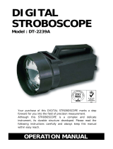
For example, when viewing a shaft with a single key way, you will see one stationary image of the
key way at the actual speed and at 1/2,1/3,1/4, etc, of the actual speed. You will see 2 images of the
key way at 2 times the actual speed, 3 key way images at 3 times, etc. (see Figure 6). The Flash Per
Minute (FPM) equals the shaft’s Revolutions Per Minute (RPM) at the highest flash rate
that gives only one stationary image of the key way.
Figure 6 Object Rotating at 3000 RPM
If the speed is outside the full scale range of the stroboscope (12,500 FPM), it can be measured using
the method of harmonics and multipoint calculation. Start at the highest flash rate and adjust the
flash rate down. Be aware that you will encounter multiple images. Note the flash rate of the first
SINGLE image you encounter, and call this speed “A”. Continue decreasing the flash rate until you
encounter a second SINGLE image, and note this speed as “B”. Continue decreasing the speed until
you reach a third SINGLE image at speed “C”.
For a two point calculation the actual speed is given by: RPM = AB/(A-B)
For a three point calculation: RPM = 2XY(X+Y)/(X-Y)
2
where
X = (A-B) and
Y = (B-C)
If a Self-Powered Sensor is used to sense one pulse per revolution (External Input Mode), the
readout will display directly in RPM (FPM) without any adjustment required.
In instances when you can shut down the device and install a piece of reflective tape, then an optical
tachometer is easier to use for RPM measurement. You can use the PALM STROBE x with an
external sensor as an optical tachometer. Stroboscopes need only be used as a tachometer when
you can’t shut down the device. The human eye is not easily tricked into seeing a stopped image
by a stroboscope when the flash rate is slower than 300 FPM. Therefore, a stroboscope image is
difficult to use below 300 FPM for inspection or to measure RPM.
6
Stopped Image 1/4 times 1/2 times 1 time 2 times 3 times 4 times
Flash Rate (FPM) 750 1500 3000 6000 9000 12000
www.64817.com
  • Page 1 1
  • Page 2 2
  • Page 3 3
  • Page 4 4
  • Page 5 5
  • Page 6 6
  • Page 7 7
  • Page 8 8

Monarch PALM STROBE x Pocket-Size User manual

Category
Camera flashes
Type
User manual

Monarch PALM STROBE x Pocket-Size is a compact, single-handed stroboscope that fits in the palm of your hand and allows you to accurately measure and adjust the speed of rotating or reciprocating machinery. With a flash rate range of 100 to 12,500 flashes per minute, it can freeze motion for detailed inspection or synchronization.

Ask a question and I''ll find the answer in the document

Finding information in a document is now easier with AI