Page is loading ...

DIGITAL
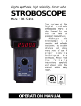
STROBOSCOPE
Model : DT-2239A
Your purchase of this DIGITAL STROBOSCOPE marks a step
forward for you into the field of precision measurement.
Although this STROBOSCOPE is a complex and delicate
instrument, its durable structure developed. Please read the
following instructions carefully and always keep this manual
within easy reach.
OPERATION MANUAL

Warning
Do not look directly at strobe/reflector.
Light pulses at the frequency greater than
5 Hz may cause photosensitive epilepsy in
some individuals if directly viewed.
A feature of the instrument is to make
moving objects appear to be stationary.
Precaution should therefore be taken to
ensure that there is no physical contact
made with objects being viewed.

Caution Symbol
Caution :
* Risk of electric shock !
Caution :
*
Do not use fingers or any tool
to touch the FLASH TUBE.
*
The instrument contains no user
serviceable parts and should not
be opened by the user.
*
Repair or after service should be
done by a qualified technician
only.
* Power plug should apply the correct
ACV power voltage
* Operating duty cycle should be
adhered to.
* Cleaning - Only use the dry cloth to
clean the plastic case !
Environmental Condition
* Comply with EN61010 Installation
category II 300 Vac.
* Pollution Degree 2.
* Altitude up to 2000 meters.
* Indoor use.
* Relative humidity 80% max.

TABLE OF CONTENTS
1. FEATURES...............................................................
.
1
2. SPECIFICATIONS...................................................... 1
2-1 General Specification..........................................
.
1
2-2 Flash Tube Specification...................................... 2
3. FRONT PANEL DESCRIPTION....................................
.
3
3-1 Power On/Off Switch..........................................
.
3
3-2 Low/Hi
g
h Ran
g
e Select Switch............................
.
3
3-3 Fine Ad
j
ust Knob................................................
.
3
3-4 Coarse Ad
j
ust Knob............................................
.
3
3-5 Flash Tube......................................................... 3
3-6 Auto Ran
g
e Indicator.......................................... 3
3-7 Display............................................................... 3
3-8 Power Cord Input Socket....................................
.
3
3-9 Power Cord Connector........................................
.
3
3-10 Power Cord Plu
g
............................................... 3
4. MEASURING PROCEDURES 4
4-1 Preparation.......................................................
.
4
4-2 Checkin
g
Speed................................................. 4
4-3 Checkin
g
Motion................................................ 5
5. FLASH TUBE REPLACEMENT.....................................
.
5
6. THE ADDRESS OF AFTER SERVICE CENTER............... 6

1. FEATURES
The Digital Stroboscope is a microprocessor circuit design,
high accuracy, digital readout, light duty, that is ideal for
inspecting and measuring the speed of moving gears, fans,
centrifuges, pumps, motors and other equipment used in
general industrial maintenance, production, quality control,
laboratories and as well as for schools and colleges for
demonstrating strobe action.
2. SPECIFICATIONS
2-1 General Specification
Display 0.4" LED, 4 digits.
Stroboscopic 100 to 10,000 flashes per
Flash Rate minute (FPM).
Accuracy ( 0.05% + 1 digit ).
*
Spec. tested under the environment
RF Field Strength less than 3 V/M &
frequency less than the 30 MHz only.
Resolution 0.1 FPM/RPM ( less than 1,000 FPM/RPM )
1 FPM/RPM ( 1,000 to 9,999 FPM/RPM ).
10 FPM/RPM ( over 10,000 FPM/RPM )
Sampling Time 1 second.
Range Select High/Low range
Low range : Approx. 100.0 to 1,200 RPM
High range : Approx. 1,000 to 10,000 RPM
Circuit One chip of microcomputer LSI circuit &
crystal control time base
1

Power Supply 110 Vac 10%, 50/60 Hz.
220 Vac 10%, 50/60 Hz.
230 Vac 10%, 50/60 Hz.
240 Vac 10%, 50/60 Hz.
Power Less than 30 Watt.
Consumption
Operating Temp. 0 to 50 ( 32 to 122 ).℃℉
Operating Less than 80% R.H.
Humidity
Dimension 21 x 12 x 12 cm (8.3 x 4.8 x 4.8 inch).
Weight 1 Kg/2.2 LB.
Housing Compact and impact plastic injection
case with plastic mirror type reflector.
Calibration Crystal time base and microprocessor
circuit, no external calibration process
required.
Accessories Operation manual...................
.
1 PC
Included Power cord.............................
.
1 PC
2-2 Flash Tube Specification
Flash tube Xenon lamp.
Flash Duration Approximately 60 to 1000
microseconds.
Flash color Xenon white 6,500 K degree.
Flash energy 4 Watts-seconds (joules).
Beam Angle 80
Flash tube It may be necessary to change the
replacement xenon flash tube if the instrument starts
to flash irregularly at speeds of 3600
RPM/FPM or more.
Operating duty For prolonged life and safe operation,
Cycle please adhere to the following duty
cycle :
Below 3,000 RPM - 30 Minutes.
Above 3,000 RPM - 5 Minutes.
* Always allow a 10 minute cooling off
period between cycles.
2

3. FRONT PANEL DESCRIPTION
Fig. 1
Symbol :
3-1 Power On/Off Switch 1 = On
3-2 Low/High Range Select Switch 0 = Off
3-3 Fine Adjust Knob
3-4 Coarse Adjust Knob
3-5 Flash Tube
3-6 Auto Range Indicator
3-7 Display
3-8 Power Cord Input Socket
3-9 Power Cord Connector
3-10 Power Cord Plug
3

4. MEASURING PROCEDURE
Caution :
* Do not use fingers or any
tool to touch the FLASH
TUBE.
* Risk of electric shock !
4-1 Preparation
a. Connect the " Power Cord Connector " (3-9, Fig. 1) to
the " Power Cord Input Socket " (3-8). Plug the " Power
Cord Plug " (Fig. 1, 3-10) into a properly grounded
110V AC, 220V AC or 240V AC outlet.
Caution :
* The power plug should be
connected to the correct AC
power supply.
b. Turn the power switch to " On " position.
c. Determine the range switch to "Low" or "High" position.
4-2 Checking Speed (RPM/FPM)
Caution :
* Operating duty cycle
should be followed.
For prolong life and safety, please adhere to the
following operation duty :
Below 2,000 RPM - 30 Minutes.
Above 2,000 RPM - 5 Minutes.
*
Always allow a 10 minute cooling off period between cycles.
4

a. Power off the installation to be measured, make a " mark "
on the rotation area where it is intended to measure the RPM.
Then power on the installation to be measured.
b. When checking the speed, care must be taken to ensure
that the strobe is flashing in unison (one to one) with the
object being monitored. Turn the " Fine Adjust Knob "
(3-3, Fig. 1) or " Coarse Adjust Knob " (3-4, Fig. 1)
until the mark look like " Stop " ( synchronize ).
c. The Stroboscope will also stop motion at 2:1, 3:1, 4:1 et.,
this is normally referred to as harmonics. To ensure
unison, turn the dial until two images appear - this will
double the actual speed. Then lower the flashing rate
until a single and stationary image appears - this is the
actual true speed.
4-3 Checking Motion
For motion analysis, simply locate the actual speed as
mentioned above and then turn the dial slowly up or down.
This will give a slow motion effect allowing complete
inspection.
5. FLASH TUBE REPLACEMENT
The flash tube requires changing when the instrument start
to flash erratically at speeds of 3600 RPM/FPM or more.
Caution :
* Change of the Flash Tube
should only be done by a
qualified technician. As the
instrument contains no user
serviceable parts.
5

6. THE ADDRESS OF AFTER SERVICE
CENTER
6
0804-DT2239
/