Page is loading ...

VC7000 Series
100V LINE SPEAKER VOLUME CONTROLLERS
4 WIRE SYSTEM
Thank you for selecting another fine product from Amperes, VC7000 Series of volume controllers which had been
a popular item in the market.
It is available in various variants from 5W to 150W 100V line, and also in different format of face plate, namely 86
x 86 mm or 70 x 120 mm.
Installing this unit shall not be difficult but a thorough read through of this manual is recommended in order to
avoid any undesired results and also to tap the full potential of what this unit could offer.
Please keep this manual for future references.
Installation Guide
INSTALLATION PROCEDURES
Cables from amplifier, to speakers and the overriding 24V DC shall be
connected to the module before mounting to the back enclosures.
Recommended cable size shall not be more than 2.5mm sq.
The termination marking is available and shall be :
SPK - 100V line hot ( +ve ) to speaker
AMP - 100V line hot ( +ve ) from amplifier
COM - Common for amplifier and speaker cable
+24 - 24V DC overriding ( +ve )
-24 - 24V DC common ( -ve )
Cable connections not shown
Install the cabled VC module to the back enclosure using M3 screw
provided.
For ease of installation, please do not allow too lengthy cables which
may also cause damage to the VC module during installation.
WALL
2 X 24V DC
Overriding Cable
2 x Audio 100V
Cable
Back Enclosure
1 : INCOMING CABLES
As the volume controllers works in a 4 wire system, there should be 2 x
100V line audio circuit from power amplifiers and another optional
2x24V DC emergency overriding cable from the rack.
Please use back enclosure of 50 mm depth either surface or concealed
type for volume controller versions with back step down transformer (
except VC7010 resistive type )
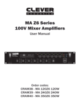
Rear Side of Volume
Controller
Matching Transformer
Cable Terminals
8 mm Stripped Copper
Conductor
Incoming Cables from Wall
SPK
AMP
COM
+24
-24
2 : TERMINATING CABLE TO VC TERMINALS
3 : FIXING VOLUME CONTROLLER TO THE BACK ENCLOSURE
SPEAKER VOLUME
1
2
3
4
MAX
VC Module
Back Enclosure
M3 x 25mm Screw
4 : fIXING THE COVER
SPEAKER VOLUME
1
2
3
4
MAX
COPYRIGHTS RESERVED @ AMPERES ELECTRONICS SDN BHD 2011 www.ampereselectronics.com
Locking Slots
Locking Slots
Push the Cover
Push the Cover
Front Plate Cover
VC Module
The final procedure shall be attaching the front plate cover to the VC
assembly. Gently push the cover with the locking pin to the slots to
complete the installation
/