Page is loading ...


Carmanah Technologies Corp. | 250 Bay St, Victoria, BC V9A 3K5, Canada | 1.250.380.0052 | cust[email protected]om | carmanah.com 2
G SERIES QUICK START GUIDE
1.1 Safety Precautions
ELECTRICAL SHOCK HAZARD. DO NOT ALLOW THE BATTERY TERMINALS COME INTO
CONTACT WITH ANY EXPOSED METAL.
Product can have sharp edges. Accidental movement of hinged components can cause injury.
Batteries are shipped fully charged. Use extreme caution when handling the batteries as they can
generate hazardous short-circuit currents. Remove all jewelry (bracelets, metal-strap watches,
etc.) before handling the batteries.
Solar panels produce DC electricity when exposed to light and can therefore cab produce an
electrical shock or burn. To render solar panels inoperative, remove them from sunlight or fully
cover their front surface with an opaque material.
Before lifting any heavy or bulky equipment, ensure the load is secured so moving parts do not
shift, and that it can be lifted as far as needed without back strain or loss of grip. Installation may
require more than one person.
Ensure the equipment is not energized during installation.
Recheck all completed wiring for proper polarity prior to energizing the system.
Perform all installation, wiring, grounding, and maintenance in conformance with local building
and electrical codes. Adherence to the National Electrical Code (NEC) is mandatory to comply
with any certification markings. Non-adherence to code may void the warranty.
Changes or modifications to Carmanah equipment not expressly approved by Carmanah could
void both the user's authority to operate the equipment and warranty.
For solar applications, ensure the installation location has an unobstructed view of the sun’s path.
Obstructions such as trees or buildings could significantly reduce the amount of sunlight on the
solar panel. Shade analysis is highly recommended to understand how shadows will change
according to the time of year. Contact Carmanah for a detailed examination and solar simulations
for your site.
This quick start guide is not a replacement for the complete product user manual.
Visit support.carmanah.com to download the complete product user manual.
2.1 Tools and Materials Required
The following tools and materials may be required to mount your Carmanah flashing beacon depending on the G
Series model and configuration:
a. Imperial socket set
b. Crescent wrench
c. Tap set
d. Imperial Allen-Wrench set
e. Fish tape
f. Level
g. Compass or pre-determined equatorial
direction
h. Drill and drill bits
i. Fine tip felt marker
j. Multi-bit screwdriver
k. Pelco Roger-Wrench (Optional)
l. Ladder or lift device
m. Lithium grease
n. Electrical Multi-meter (Optional)

Carmanah Technologies Corp. | 250 Bay St, Victoria, BC V9A 3K5, Canada | 1.250.380.0052 | cust[email protected]om | carmanah.com 3
G SERIES QUICK START GUIDE
3.1 Commissioning
After installing and programming the G Series flashing beacon system, the following commissioning verification
checklist helps ensure that everything is working as intended:
EMS settings are correct.
No LED fault message on the EMS.
For single or triple fixture systems, ensure the flash pattern is set for unison 0.5U or 0.5A3.
Fixtures flash properly:
Use “TEST” at the EMS user interface to check functionality of LED fixtures.
All fixtures are mounted securely and pointed in the correct direction toward oncoming traffic lanes.
For school zone systems, retrieved calendar from R829-G is confirmed to be accurate.
Solar panel pointed South (or as per specific instructions provided by Carmanah).
- Not applicable for AC powered models.
Override box (if equipped) correctly activates or deactivates the flashing (depending on model input
setting).
The solar panel is properly mounted, and the mount is secure.
- Not applicable for AC powered models.
No debris covering the photosensor window on top of the solar engine.
Vents are clear, and screens are intact.
Sealing gaskets on door are intact.
Solar panel is producing voltage in sunlight (use EMS “Solar” user interface menu item).
- Not applicable for AC powered models.
System has clear-sky access, and no removal of obstructions is required.
- Not applicable for AC powered models.
Note the possibility for nearby foliage to eventually shade the solar panel at a different time of year. If so,
set a reminder to inspect later.
- Not applicable for AC powered models.
Battery voltage is healthy (use either a voltmeter or EMS “Battery” user interface menu item).
- Not applicable for AC powered models.
Verify both fuses are intact (use voltmeter to confirm fuse continuity).
RRFB light bar flashing starts with left LED module first.
Remote systems are turning on and off correctly via wireless control.
For RRFB systems, verify the indicator LEDs on the ends of light bars can be seen by pedestrians across
the street.
Ensure cabinet door is fully closed and latched.

Carmanah Technologies Corp. | 250 Bay St, Victoria, BC V9A 3K5, Canada | 1.250.380.0052 | cust[email protected]om | carmanah.com 4
G SERIES QUICK START GUIDE
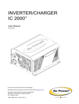
4.1 Solar Panel Mounting (Side of Pole)
1. Mark position of solar panel mount on pole and drill a suitable hole for the solar panel wires. Follow
instructions supplied with mount. Install using 45° tilt angle. Ensure solar panel is facing South (for
Northern Hemisphere locations).
2. Route supplied solar panel wires down pole and through hole for cabinet conduit nipple.
Hole drilled for
cabinet nipple

Carmanah Technologies Corp. | 250 Bay St, Victoria, BC V9A 3K5, Canada | 1.250.380.0052 | cust[email protected]om | carmanah.com 5
G SERIES QUICK START GUIDE
4.2 Solar Panel Mounting - Top of Pole (Legacy Galvanized Steel Mount)
1. Attach solar panel to top of pole mount using supplied ¼” bolts, washers and locknuts. Leave nuts finger
tight. DO NOT FULLY TIGHTEN at this stage.
2. Insert cap into pole top and slide bracket onto the pole.

Carmanah Technologies Corp. | 250 Bay St, Victoria, BC V9A 3K5, Canada | 1.250.380.0052 | cust[email protected]om | carmanah.com 6
G SERIES QUICK START GUIDE
3. Ensure panel mount sits securely on the top of pole cap, as shown below (image shows solar panel
removed for illustration purposes). Orient so panel faces South (in Northern Hemisphere).
4. Install and tighten supplied 5/8” bolts with nuts and washers.

Carmanah Technologies Corp. | 250 Bay St, Victoria, BC V9A 3K5, Canada | 1.250.380.0052 | cust[email protected]om | carmanah.com 7
G SERIES QUICK START GUIDE
5. Tighten ¼” bolts and nuts securing solar panel to mount.
6. Route supplied solar panel wires down pole and through hole for cabinet conduit nipple.

Carmanah Technologies Corp. | 250 Bay St, Victoria, BC V9A 3K5, Canada | 1.250.380.0052 | cust[email protected]om | carmanah.com 8
G SERIES QUICK START GUIDE
4.3 Solar Panel Mounting - Top of Pole (Cast Mount)
1. Install grommet and thread 6x 3/8” bolts into casting. Only thread in a couple turns so bolts do not
protrude inside.
2. Attach both sheet metal brackets to casting with supplied 3/8” bolts and washers.

Carmanah Technologies Corp. | 250 Bay St, Victoria, BC V9A 3K5, Canada | 1.250.380.0052 | cust[email protected]om | carmanah.com 9
G SERIES QUICK START GUIDE
3. Attach solar panel to top of pole mount using supplied ¼” bolts, washers and locknuts. Leave fasteners
finger tight. DO NOT FULLY TIGHTEN at this stage.
4. Slide casting over top of pole and orient so panel faces South (in Northern Hemisphere). Tighten the 6x
3/8” bolts to secure casting to pole (solar panel not shown for illustration purposes).
1/4" Nyloc Nut
1/4" Washer
1/4" Bolt

Carmanah Technologies Corp. | 250 Bay St, Victoria, BC V9A 3K5, Canada | 1.250.380.0052 | cust[email protected]om | carmanah.com 10
G SERIES QUICK START GUIDE
5. Tighten ¼” bolts and nuts securing solar panel to mount.
6. Route supplied solar panel wires down pole and through hole for cabinet conduit nipple.
4 X
Hole drilled for
cabinet nipple

Carmanah Technologies Corp. | 250 Bay St, Victoria, BC V9A 3K5, Canada | 1.250.380.0052 | cust[email protected]om | carmanah.com 11
G SERIES QUICK START GUIDE
4.4 Cabinet Mounting
1. Mark the positions of the flashing beacon(s), LED sign(s) or light bar(s) and cabinet on pole. Drill holes for
cables and pipe nipple exit/entry points as shown below.

Carmanah Technologies Corp. | 250 Bay St, Victoria, BC V9A 3K5, Canada | 1.250.380.0052 | cust[email protected]om | carmanah.com 12
G SERIES QUICK START GUIDE
Before mounting the cabinet to the pole, all wiring internal to the pole (power, LED, optional
StreetHub™ serial communications and ground cables) should be fished through the pole.
1. Loosen four nuts on back of cabinet and spread brackets outward. Tighten nuts to 20 ft-lb.
On the back of the cabinet, there are 2 drill points that may be used for routing of liquid-tight
conduit external to the mounting pole. Prior to drilling the cabinet, ensure there are no
components which may be damaged on the inside of the cabinet.
An optional hole plug kit is available if the pipe nipple is removed from the cabinet (see below).
Hole Plug
Hole Plug Installed
Drill points for external cable routing
Mounting Bracket Retention Nuts

Carmanah Technologies Corp. | 250 Bay St, Victoria, BC V9A 3K5, Canada | 1.250.380.0052 | cust[email protected]om | carmanah.com 13
G SERIES QUICK START GUIDE
2. Route the beacon or light bar harnesses through cabinet pipe nipple.
3. Route solar panel wires into cabinet and install cabinet onto pole with optional U-bolt kit or suitable
banding (not supplied).
U-Bolts Banding (brackets extended) Banding (brackets retracted)
Hole drilled for
cabinet pipe nipple
Hole drilled for
flashing beacon
harness

Carmanah Technologies Corp. | 250 Bay St, Victoria, BC V9A 3K5, Canada | 1.250.380.0052 | cust[email protected]om | carmanah.com 14
G SERIES QUICK START GUIDE
4. Connect the beacon/light bar harness(es) to the LED terminals. For light bars, use “RRFB” wire colors
shown on label. For beacons or signs use “Round” wire colors shown on label. If a pushbutton is used,
connect push-button terminals: red to INPT(+), black to INPT(−).
5. Connect solar panel harness to terminals on right side of cabinet: red wire with yellow heat shrink to Solar
(+), black wire with brown heat shrink to Solar (−).

Carmanah Technologies Corp. | 250 Bay St, Victoria, BC V9A 3K5, Canada | 1.250.380.0052 | cust[email protected]om | carmanah.com 15
G SERIES QUICK START GUIDE
6. Install and connect the battery using the color-coded wires as shown on the terminal wiring label (red to
positive, black to negative).
7. Connect solar panel harness to the solar panel. Solar panel connectors and excess cable can be coiled
up and tie-wrapped underneath the solar panel.
8. For AC systems, connect AC input wires according to the label description Black / HOT to the circuit
breaker, White / NEUTRAL to the terminal block and Green / GROUND to the ground bus bar.
Ensure cabinet door is fully closed and latched once all internal wiring connections and
system configuration have been completed; otherwise, damage may occur to cabinet door
or internal components.

Carmanah Technologies Corp. | 250 Bay St, Victoria, BC V9A 3K5, Canada | 1.250.380.0052 | cust[email protected]om | carmanah.com 16
G SERIES QUICK START GUIDE
4.5 RRFB Light Bars Installation (SC315-G)
1. Feed light bar cable(s) through post, creating a drip loop.
2. Mount light bar universal bracket(s). Bolts and banding not supplied.
3. Mount light bar(s) onto universal bracket(s) through slots in back. Bolt light bar to universal bracket as
shown. Install two anti-vandal rotation locking screws. Tighten mounting nuts. Secure cable using
supplied cable ties as shown.
4. Align light bar as required. Push light bar wires into light bar connectors, following color scheme indicated
on unit. For FHWA compliance, mount light bar so black and white wires are on the left side. Slide
on light bar cover and secure with four screws provided. If the pedestrian confirmation light is not required
in one direction, use the supplied opaque label to cover the indicator light.

Carmanah Technologies Corp. | 250 Bay St, Victoria, BC V9A 3K5, Canada | 1.250.380.0052 | cust[email protected]om | carmanah.com 17
G SERIES QUICK START GUIDE
4.6 RRFB Light Bar Backplates (R920-E/F)
1. With the light bar already installed and wired, install the backplate over and behind the light bar with the
flanges facing forward.
2. Install light bar cover and align screw holes.
3. Slide back plate flanges forward over light bar cover.
4. Align and install four screws several turns, then tighten all four.
5.1 Pushbutton Installation (SC315-G / R820-G)
If the G Series is wired for a pushbutton but none is needed (such as an
advance RRFB), insulate the ends and secure the wires.
The pushbutton can be connected in either polarity.
1. For round poles, cut holes to size and tap as required. Deburr the hole that the pushbutton wiring will
pass through.
2. Feed the pushbutton cable through the pole, creating a drip loop.

Carmanah Technologies Corp. | 250 Bay St, Victoria, BC V9A 3K5, Canada | 1.250.380.0052 | cust[email protected]om | carmanah.com 18
G SERIES QUICK START GUIDE
5.2 Polara iNX and iDX Audible Pushbutton Kit Installation
This section applies to both the iNX and iDX (touchless) audible pushbuttons.
The Polara iNX/iDX series supersedes the XAV audible pushbutton and integrates the controller inside the
pushbutton assembly. The iNX/iDX pushbutton kit includes a pushbutton harness (available in 16ft, 36ft or 75ft
lengths), the iNX/iDX audible pushbutton assembly, and the R10-25 pedestrian pushbutton sign.
The Digital Output on the EMS must be set to ALL when used with the iNX/iDX pushbuttons on
standard systems.
For systems with no installed LED fixtures, the Digital Output must be set to “nLED.” This
function requires the EMS to have firmware version 1.1.5.0 or newer. See Firmware Version in
Section 6.1 in the complete user manual for instructions on how to check the EMS firmware
version.
1. Connect the iNX/iDX harness to the EMS and
pushbutton terminals as detailed below. Torque EMS
terminal block screws to 12 in-lb. Please consult
Polara’s installation documentation for more
information.
iNX/iDX Terminal
Wire Color
EMS Terminal
Function
GND
Black
DC-
Battery Negative
PWR
Red
DC+
Provides +12V power to pushbutton
BUTTON
(Non-Polarized)
Orange
INPT+
Triggers EMS to activate beacons
Brown
INPT-
Triggers EMS to activate beacons
LIGHTS
(Non-Polarized)
Blue/Black
DC-
Battery Negative
Yellow
OUT2
Provides confirmation signal that beacons are flashing
to iNX/iDX - triggering audible message
2. Secure cable to EMS near terminal block using cable tie.
3. Check that the button is configured correctly.
Onsite configuration of the pushbutton can be done via the iNX/iDX Android and iOS app, refer
to the Polara iNX/iDX user manual for details.
Ensure that the “wireless sync” feature is disabled. Go to Wireless Sync from the app homepage.
Ensure that the flash pattern in the Polara app corresponds to the beacon flash pattern. The default is set to
“rapid flash,” suitable for RRFBs. In the settings menu, under LED Flash Behavior, select the Play Predefined
Pattern option and chose the appropriate option based on the EMS flash pattern (see reference table below):
EMS Flash pattern
iNX/iDX flash pattern
rFb, rFb2, 0.1u, 0.25u, 0.1uF, 0.1AF
Rapid Flash
0.5u, 0.5A, 0.5A3
Simple On/Off
stdY
Solid LED On

Carmanah Technologies Corp. | 250 Bay St, Victoria, BC V9A 3K5, Canada | 1.250.380.0052 | cust[email protected]om | carmanah.com 19
G SERIES QUICK START GUIDE
5.3 Campbell Guardian Audible Pushbutton Kit Installation
The Campbell Guardian audible pushbutton kit includes a pushbutton harness (16ft, 36ft or 75ft) prewired to the G
Series EMS (as shown below), along with the Guardian audible pushbutton, and an associated sign. Please
consult Campbell’s installation documentation for more information.
The Digital Output on the EMS must be set to ALL when used with the Guardian pushbutton on
standard systems.
For systems with no installed LED fixtures, the Digital Output must be set to nLED. This function
requires the EMS to have firmware version 1.1.5.0 or newer. See Firmware Version in Section
6.1 in the complete user manual for instructions on how to check the EMS firmware version.
Contact Carmanah for instructions if adding an audible pushbutton to an older system.
Campbell
Terminal
Wire Color
Terminal Block
Connection
Function
Field terminal
Orange
INPT+
1 of 2 pushbutton inputs to EMS from Guardian
Field terminal
Brown
INPT−
2 of 2 pushbutton inputs to EMS from Guardian
+12VDC
Red
DC+
Positive side of 12-volt power supply for Guardian
-GND
Black
DC−
Negative side of 12-volt power supply for Guardian
W (Walk)
Yellow
OUT2
Guardian sense line for triggering recorded message
when fixture flashing is detected
Not Used
Blue/Black
DC-
Not Used, apply tape to wire end or trim at jacket exit
DW (Don’t Walk)
Not used

Carmanah Technologies Corp. | 250 Bay St, Victoria, BC V9A 3K5, Canada | 1.250.380.0052 | cust[email protected]om | carmanah.com 20
G SERIES QUICK START GUIDE
6.1 EMS Programming and Testing
The G Series’ Energy Management System (EMS) has several programming functions and settings. These are
accessed through the On-Board User Interface (OBUI). Specific products will use a subset of the complete OBUI
settings, which are covered in the full user manual’s sections specific to each product.
6.2 EMS On-Board User Interface Operation
The EMS OBUI has three buttons to navigate and change settings and activate functions as required. The Up
arrow, Down arrow and SET button are used to scroll through menus, access settings and accept changes to
settings.
Use the Up or Down buttons to initially activate the OBUI and illuminate the display.
See following sections which contain both an image of the cabinet door label and an expanded list of settings and
functions.
For RRFBs and crosswalk beacons, use the input type bttn (button) only. All other
options are non-compliant and not to be used.
/