Page is loading ...

Assembly Instructions
8000980-01
75E LFL Antenna and
75E LFL Co-Located Antenna Systems
Printed in U.S.A.
ECN 9000000
4/05 8000980-01
Andrew Corporation
10500 West 153rd Street
Orland Park, IL U.S.A. 60462
Telephone: 708-349-3300
Fax (USA): 1-800-349-5444
www.andrew.com
satcom@andrew.com
AntennaTechSupport@andrew.com
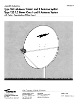
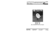
75E LFL ANTENNA
75E LFL CO-LOCATED ANTENNA
AZ/EL
MOUNT
TO
P
T
O
P
REFLECTOR
SUPPORT
ARM
FEED
SUPPORT
BRACKET
WAVE
GUIDE
BEND
Rx/Tx FEED
ASSEMBLY
TO
P
T
O
P
WAVE
GUIDE
BEND
CO-LOCATED
FEED ASSEMBLY
FEED
SUPPORT
BRACKET
SUPPORT
ARM
AZ/EL
MOUNT
REFLECTOR
LNB
(CUSTOMER
PROVIDED)
BUC
BRACKET BUC
(CUSTOMER PROVIDED)
BUC
(CUSTOMER PROVIDED)
LNB
(CUSTOMER PROVIDED)

MANUAL REVISION HISTORY
3/05 ECN 9000000 RELEASE
DATE DESCRIPTION REVISION
WARNINGS
DANGER: WATCH FOR WIRES! Installation of this product near power lines is
extremely dangerous and must never be attempted. Installation of this
product near power lines can result in death or serious injury!
For your own safety, you must follow these important safety rules.
Failure to follow these rules could result in death or serious injury!
1. Perform as many functions as possible on the ground
2. Watch out for overhead power lines. Check the distance to the
power lines before starting installation. Stay at least 6 meters (20 feet)
away from all power lines.
3. Do not install antenna or mast assembly on a windy day.
4. If you start to drop antenna or mast assembly, move away from it
and let it fall.
5. If any part of the antenna or mast assembly comes in contact with a
power line, call your local power company. DO NOT TRY TO
REMOVE IT YOURSELF! They will remove it safely.
6. Make sure that the mast assembly is properly grounded.
WARNING: Assembling dish antennas on windy days is extremely dangerous and
must never be attempted. Due to the surface area of the reflector, even
slight winds create strong forces. For example, this antenna facing a
wind of 56 km/h (35 mph) can undergo forces of 169 N (38 lbs.) BE
PREPARED TO SAFELY HANDLE THESE FORCES AT UNEXPECTED
MOMENTS. ATTEMPTING TO ASSEMBLE, MOVE OR MOUNT A DISH
ON WINDY DAYS COULD RESULT IN DEATH OR SERIOUS INJURY.
ANDREW is not responsible or liable for damage or injury resulting from
antenna installations.
WARNING: Antennas improperly installed or installed to an inadequate structure are very
susceptible to wind damage. This damage can be very serious or even life
threatening. The owner and installer assumes full responsibility that the
installation is structurally sound to support all loads (weight, wind and ice)
and properly sealed against leaks. ANDREW will not accept liability for any
damage caused by a satellite system due to the many unknown variable
applications.
1

PREINSTALLATION CONSIDERATIONS
SITE SELECTION
DESCRIPTION:
The 75 cm Elliptical Antenna System is designed for two-way
satellite communications, and is suitable for commercial or consumer use.
TOOLS REQUIRED:
1 - Compass
1 - Inclinometer
1 - 9” Magnetic Level
1 - Screwdriver (#1 and #2 Phillips)
1 - 10 mm/13 mm Open End Wrench
1 - 3/32" Allen Wrench (Included)
ADDITIONAL TOOLS:
1 - 10 mm Nut Driver
1 - Torque Wrench
1 - Ratchet Wrench (3/8" Drive)
1 - 13 mm Socket (3/8” Drive)
1 - 10 mm Socket (3/8” Drive)
CARTON CONTENTS:
Contents listed on Parts
List documentation.
Save Parts List for future
reference.
ADDITIONAL PREINSTALLATION MATERIALS
Grounding Rod, Clamp & Grounding Block
(As required by National Electric Code or local codes.)
Ground Wire - #10 solid copper or #8 aluminum
(As required by National Electric Code or local codes.) (length required).
RG-6 Coaxial Cables from antenna to indoor unit(s).
Installation Mount (As required by site survey.)
The main objective in conducting a site survey utilizing a compass and inclinometer is to choose a mounting location that
will give you the greatest amount of swing for azimuth and elevation for present as well as future use. A thorough
preinstallation site survey is strongly recommended because it can alert you to any “look angle”, soil, wind or other
problems.
The first and most important consideration when choosing a prospective antenna site is whether or not the area can
provide an acceptable “look angle” to the satellite. Your antenna site must be selected in advance so that you will be
able to receive the strongest signal available. Also consider obstructions that may occur in the future such as the
growth of trees.
Prior to beginning the site survey, the site location and satellite look angles must be determined.
Determine your site latitude and longitude and enter the values here:
Based on your site location and the satellite to be used, determine the correct azimuth, elevation, and skew settings for
your installation. Using the charts (beginning on Page 11), obtain these values and enter them here for easy reference.
Enter the values here:
It is important to conduct an on-site survey with a portable antenna or with a compass and inclinometer to avoid
interference, obstructions, etc. When selecting “look angle,” (Elevation/Azimuth) be sure to observe and take
readings approximately 25 degrees to the left and right, above and below your selected “look angle”.
Once you have chosen a site, select a location and determine the type of installation mount to be used. The satellite
antenna can be installed on a ground pole, wall/roof mount, or non-penetrating roof mount with 60 mm (2-3/8”) outside
diameter mast. The chosen mount type should be assembled and in place before installing the antenna. Refer to instructions
packed with mount for its proper installation. The mast pipe must be vertical and plumb to insure ease of alignment.
Before any digging or trenching for Interfacility Link (IFL) cables is done, information regarding the possibility of
underground telephone lines, power lines, storm drains, etc., in the excavation area should be obtained from the
appropriate agency.
As with any other type of construction, a local building permit may be required before installing an antenna. It is the
property owner’s responsibility to obtain any and all permits.
AZIMUTH ELEVATION SKEW
LATITUDE LONGITUDE
2

HARDWARE
3
6000735-01
6000736-01 (75E LFL Antenna Only)
6000737-01
M8 Plow Bolt 60mm M8 Plow Bolt 80mm Skew Clip
M8 Hex Bolt 70mm
M8 Lock Washer
Flat Washer M8 Nut
6000738-01 (75E LFL Co-Located Antenna Only)
M4 Philips Head Screw 10 mm M4 Philips Head Screw 16 mm
M4 Lock Washer M4 Flat WasherM4 Nut Wave Guide BendBUC Bracket
M4 Philips Head Screw 10 mm M4 Philips Head Screw 16 mm
M4 Lock Washer M4 Flat WasherM4 Nut
Wave Guide Bend
M6 Hex Head 60 mm Bolt M6 Flat Washer
M6 Lock Washer M6 Philips Head Screw 16mm
M6 Nut
Feed Support Bracket

ANTENNA ASSEMBLY
4
1
2
FEED
BRACKET
M8 x 60 mm
(2.38 inch)
PLOW BOLT
LOWER AREAS
(2 PLACES)
M8 x 80 mm
(3.15 inch)
PLOW BOLT
(2 PLACES)
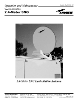
Place Reflector on flat surface or table. Attach AZ/EL Mount to Reflector using (2) M8 x 80 mm (3.15 inch) and (2)
M8 x 60 mm (2.38 inch) Plow Bolts, (4) Skew Lock Clips, (4) Lock Washers and (4) M8 Hex Nuts. The 80 mm (3.15 inch)
Plow Bolts are inserted through the top two holes of the Reflector and the 60 mm (2.38 inch) Plow Bolts are inserted through
the lower two holes. The AZ/EL Mount is secured to the Reflector with (4) Skew Lock Clips as illustrated in the Rear View Detail
above. Loosely tighten nuts. Before tightening the hardware securely, see the Skew Setting Chart provided on page 9 of this
manual. When proper skew is set and aligned to the Skew Alignment Mark, tighten hardware securely.
SKEW
ALIGNMENT
MARK
REAR VIEW DETAIL
M8 x 60 mm
(2.38 inch)
PLOW BOLT
LOWER AREAS
(2 PLACES)
SKEW
LOCK CLIP
(4 PLACES)
M8 LOCK WASHER
(4 PLACES)
M8 HEX NUT
(4 PLACES)
T
OP
SKEW
LOCK CLIP
(4 PLACES)
M8 LOCK
WASHER
(4 PLACES)
M8 HEX NUT (4 PLACES)
AZ/EL
MOUNT
AZ/EL
MOUNT
REFLECTOR
Attach Feed Bracket to Support Arm with
M6 x 60 mm Hex Head Screw, Lock Washer,
Flat Washer and M6 Hex Nut. Tighten
hardware securely.
NOTE:
M6 Hex Nut
inserts in preformed
slot in Feed Bracket.
NOTE:
Location of Small Hole (M6) is
on top side of Support Arm.
(Away from Reflector) Large Hole
(M8) is on top toward reflector.
SUPPORT ARM
SMALL HOLE
(M6)
LARGE HOLE
(M8)
DETAIL VIEW
M6 FLAT
WASHER
M6 LOCK
WASHER
M6 x 60 mm
HEX HEAD
SCREW
M6
HEX NUT
FEED
BRACKET
SUPPORT ARM
IMPORTANT: Steps 2 through 6 must be completed on table or
ground level BEFORE attempting final mounting assembly
of reflector. Place Bracket on Support Arm over Small (M6) Hole.

75E RX TX FEED ASSEMBLY
5
3
Align Flange Holes of RxTx Feed
Assembly with holes in Bracket and
place RxTx Feed Assembly on Bracket.
DETAIL VIEW
Secure RxTx
Feed Assembly
to Bracket with
M6 x 16 mm
Philips Head
Screws, Lock
Washers and
M6 Hex Nuts.
Firmly tighten
hardware.
FEED
SUPPORT
BRACKET
RxTx FEED
ASSEMBLY
M6 x 16 mm
PHILIPS HEAD
SCREW
(2 PLACES)
M6 LOCK
WASHER
(2 PLACES)
M6 HEX NUT
(2 PLACES)
Align Flange Holes of Co-Located Feed Assembly with holes in Feed Bracket and place Co-Located Feed Assembly on
Feed Bracket.
DETAIL VIEW
Secure
Co-Located
Feed Assembly
to Bracket with
M6 x 16 mm
Philips Head
Screws, Lock
Washers and
M6 Hex Nuts.
Firmly tighten
hardware.
M6 x 16 mm
PHILIPS HEAD
SCREW
(2 PLACES)
M6 LOCK
WASHER
(2 PLACES)
M6 HEX NUT
(2 PLACES)
CO-LOCATED
FEED
ASSEMBLY
SUPPORT
ARM
75E CO-LOCATED FEED ASSEMBLY
FEED
SUPPORT
BRACKET

75E RX TX FEED ASSEMBLY
6
4
75E CO-LOCATED FEED ASSEMBLY
Insert O-Ring in recessed area of RxTx Feed
Assembly. Align flange of Wave Guide
Bend with holes on Support arm and place
Wave Guide Bend on
Support Arm.
Attach Wave Guide Bend to Support
Arm with M4 x 16 mm Philips
Head Screws, Lock Washers,
Washers and M6 Hex Head
Nuts. Tighten securely.
M4 HEX
HEAD NUT
(2 PLACES)
M4 FLAT
WASHER
(2 PLACES)
M4 LOCK
WASHER
(2 PLACES)
M4 x 16mm
PHILIPS HEAD
SCREW
(2 PLACES)
WAVE
GUIDE
BEND
WAVE
GUIDE
BEND
SUPPORT
ARM
Attach BUC Bracket to Support Arm
with M4 x 16 mm Philips Head Screws, Lock
Washers, Washers and M4 Hex Head Nuts.
Tighten securely.
M4 HEX HEAD NUT
(2 PLACES)
M4 FLAT
WASHER
(2 PLACES)
LOCK WASHER
(2 PLACES)
M4 x 16mm
PHILIPS HEAD
SCREW
(2 PLACES)
Fasten Wave Guide Bend to BUC Bracket with M4 x 16 mm Philips Head Screws, Lock Washers, Washers, and M4 Hex
Head Nuts. Loosely tighten. Do not Tighten securely until O-Ring is inserted in Co-Located Feed Assembly.
BUC BRACKET
Align open slots
on flange of
Wave Guide Bend
with holes of
BUC Bracket
and place
Wave Guide Bend
on Buc Bracket.
BUC BRACKET
WAVE GUIDE BEND
M4 LOCK WASHER
(2 PLACES)
M4 x 16mm
PHILIPS HEAD
SCREW
(2 PLACES)
M4 HEX HEAD NUT
(2 PLACES)
M4 FLAT
WASHER
(2 PLACES)
BUC
BRACKET
WAVE GUIDE BEND
O-RING
RxTx FEED
ASSEMBLY

INSERT O-RING
7
5
M4 x 16mm
PHILIPS HEAD
SCREW
(4 PLACES)
M4 LOCK
WASHER
(4 PLACES)
Assure that O-Ring is in place and seated
in groove of RxTx Feed Assembly.
Fasten Wave Guide Bend to RxTx Feed Assembly
with M4 x 16 mm Philips Head Screws and Lock
Washers. Tighten securely.
Insert O-Ring into recessed area of Co-Located Feed Assembly. Fasten
Wave Guide Bend to Co-Located Feed Assembly with M4 x 16 mm
Philips Head Screws and Lock Washers. Tighten all hardware securely
including hardware for BUC bracket and Wave Guide Bend.
M4 x 16mm
PHILIPS HEAD
SCREW
(4 PLACES)
M4 LOCK
WASHER
(4 PLACES)
WAVE
GUIDE
BEND
CO-LOCATED
FEED ASSEMBLY
75E RxTx FEED ASSEMBLY 75E CO-LOCATED FEED ASSEMBLY
6
DETAIL
VIEW
REFLECTOR
SUPPORT ARM
Insert Support Arm Into notch located on bottom of
Reflector. Attach Support Arm to Reflector with
M8 x 70 mm Hex Head Screw, Lock Washers, Flat
Washer and M8 Hex Head Nut. Tighten securely.
M8 HEX
HEAD
NUT
M8 FLAT WASHER
M8 LOCK
WASHER
M8 x 70 mm
HEX HEAD
SCREW
M8 LOCK
WASHER
O-RING
BUC
BRACKET
7
75E RxTx FEED ASSEMBLY 75E CO-LOCATED FEED ASSEMBLY
Attach LNB and BUC to Feed Assembly
as illustrated. (LNB and BUC are provided
by Customer).
LNB
(CUSTOMER
PROVIDED)
CO-LOCATED
FEED ASSEMBLY
BUC
(CUSTOMER
PROVIDED)
LNB
(CUSTOMER
PROVIDED)
FEED
ASSEMBLY
WAVE
GUIDE
BEND
RxTx FEED
ASSEMBLY
BUC
(CUSTOMER
PROVIDED)
NOTE: Assure that O-Rings are in place for BUC and LNB installations. Screws are provided for BUC assembly.

8
9
Loosen (4) Azimuth Locking Bolts located on AZ/EL Mount and slide AZ/EL Mount over Mount Tube. Mount Tube
options may include the Tri-Mast Wall Mount, Ground Pole Mount, or Non-Pentetrating Roof Mount. Loosely
tighten (4) Azimuth Locking Bolts. Do not tighten securely untily Azimuth Alignment is determined and set.
Optional Tri-Mast Wall Mount
T
OP
TO
P
AZ/EL MOUNT
MOUNT
TUBE
(OPTIONAL)
Optional Non-Penetrating
Roof Mount
Optional Ground Pole Mount
AZIMUTH
LOCKING
BOLT
(4 PLACES)
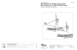
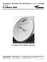
ANTENNA ALIGNMENT
SKEW ALIGNMENT
Set the SKEW on AZ/EL Skew
Mount prior to placement of
Reflector on Mount Tube. Refer
to the skew value determined on page 2.
Loosen the (four) Skew Locking Bolts
until they are just finger tight and
rotate the AZ/EL Skew Mount to align
the Skew Indicator Mark with correct
number on skew scale, as shown.
Scale is in 2
o
increments.
Tighten Skew Locking Bolts to a torque
of 8 Ft-lbs (11 Nm).
8
0
o
20
o
10
o
7
0
o
80
o
9
0
o
1
0
0
o
110
o
1
2
0
o
SKEW
INDICATOR
MARK
SKEW
LOCKING
BOLTS
(4 PLACES)
SKEW SETTING
MOUNT ASSEMBLY

9
ANTENNA ALIGNMENT
AZIMUTH ALIGNMENT
Refer to the Azimuth value
determined on page 2.
Values in chart must be adjusted for
magnetic deviation for your location for
correct compass reading. Equally tighten
the four Azimuth Locking Bolts until snug,
and loosen 1/8 turn. This will allow
azimuth rotation with slight resistance
and prevent the AZ/EL from tilting on pole.
Rotate the Reflector and Az/El Mount,
pointing it to the compass reading for your
location and satellite. If desired signal is
not located, increase or decrease elevation
setting and repeat the azimuth sweep.
Tighten progressively (1/8 turn each) all
four Azimuth Locking Bolts. Repeat until
85-95 ft-lbs. torque is reached.
Fine Tuning
Snug tighten (4) Top Plate Locking Bolts.
Turn the Azimuth Fine Tune Nut clockwise
or counterclockwise for Azimuth fine tuning.
Use an Azimuth Signal Strength measuring
device to obtain the most accurate alignment and maximum antenna performance. Alternate between elevation and
azimuth fine tuning to reach maximum signal strength, until no improvement can be detected. Tighten and torque
all hardware.
11
0
o
2
0
o
10
o
7
0
o
80
o
9
0
o
1
00
o
110
o
1
2
0
o
AZIMUTH
FINE TUNE
TOP PLATE
LOCKING
BOLT
(4 PLACES)
AZIMUTH SETTING
AZIMUTH
LOCKING
BOLTS
(4 PLACES)
ELEVATION ALIGNMENT
To obtain elevation
value for your satellite,
refer to the elevation
value written on Page 2.
IMPORTANT: Loosen Elevation Locking Bolts,
located in curved slots, on both sides. Loosen
Pivot Bolts 1/2 turn on both sides of Az/EL
Skew Mount.
Turn Elevation Adjustment Bolt clockwise to
decrease elevation and counterclockwise
to increase elevation. Position the
Elevation Alignment Indicator with
the appropriate mark on the
housing at the desired elevation
reading. Scale is in 1 degree
increments.
This will be an approximate setting.
Optimum setting is achieved when
fine tuning.
10
0
10
20
30
40
5
0
60
70
80
ELEVATION
ALIGNMENT
INDICATOR
ELEVATION
ADJUSTMENT
BOLT
ELEVATION
LOCKING
BOLT
(2 PLACES)
PIVOT
BOLT
(2 PLACES)
CLAMP
BOLT
(4 PLACES)
20
30
40
50
EXAMPLE ELEVATION SET AT 31
o

ANTENNA GROUNDING INSTRUCTIONS
10
12
IMPORTANT:
All Antenna Systems must be
properly grounded. Refer to
NEC (National Electric Code)
Article 810 and 820 and local building
codes for specific requirements.
Attach #10 AWG solid copper or #8 AWG
aluminum ground wire to Feed Assembly with
M4 x 16 mm Hex Screw, M4 Lock Washer
and Ring Clip. Tighten to assure a solid
connection. Route Ground wire through
Support Arm and down Mount Tube.
Secure Ground Wire to Mount Tube with
provided Cable Ties. Then attach Ground
Wire to Mount as shown in illustrations with
designated hardware. Tighten securely to
assure quality connection.
FEED ASSEMBLY
ROUTE GROUND WIRE
THROUGH SUPPORT ARM
RING CLIP
M16 x 16 mm
HEX HEAD SCREW
TOOTH
WASHER
RING
CLIP
M6 LOCK NUT
GROUND LUG
TRI-MAST WALL MOUNT
TOOTH
WASHER
GROUND
LUG
M16 x 16 mm
SELF TAPPING SCREW
RING
CLIP
NON-PENETRATING ROOF MOUNT
TOOTH
WASHER
RING
CLIP
GROUND
LUG
GROUND POLE MOUNT
1/4"
DRILLING SCREW
#10 AWG
SOLID COPPER
or #8 AWG
ALUMINUM
GROUND
WIRE

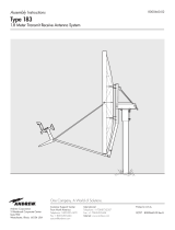
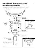
SKEW CHART
0 10 20 30 40 50 60 70 80
90
110
130
150
170
100
120
140
160
180
EARTH STATION LATITUDE IN DEGREES NORTH OR SOUTH OF EQUATOR
75
O
60
O
40
O
30
O
20
O
15
O
10
O
5
O
11
Use of Skew Chart
n Determine = the difference between your site longitude and the satellite longitude.
n Find you latitude on horizontal axis.
n Follow your latitude up until you intersect the curve for your .
n Read Skew on vertical axis.
90
110
130
150
170
100
120
140
160
180
Use Skew Value A when site longitude is West
of satellite and you are in Northern Hemisphere
Use Skew Value B when site longitude is East
of satellite and you are in Northern Hemisphere
Use Skew Value B when site longitude is West
of satellite and you are in Southern Hemisphere
Use Skew Value A when site longitude is East
of satellite and you are in Southern Hemisphere
A
B
SKEW
VALUE
SKEW
VALUE

ELEVATION CHART
EARTH STATION LATITUDE IN DEGREES NORTH OR SOUTH OF EQUATOR
ELEVATION IN DEGREES
90
80
70
60
50
40
30
20
10
0 10 20 30 40 50 60 70 80
0
ELEVATION CHART
5
O
10
O
15
O
20
O
25
O
30
O
35
O
40
O
45
O
50
O
55
O
60
O
65
O
70
O
75
O
12
Use of Elevation Chart
n Determine = the difference between your site longitude and the satellite longitude.
n Find you latitude on horizontal axis.
n Follow your latitude up until you intersect the curve for your .
n Read Elevation value on vertical axis.

AZIMUTH CHART
" L" IS THE DIFFERENCE BETWEEN THE EARTH STATION
ANTENNA SITE LONGITUDE AND THE SATELLITE LONGITUDE
ELEVATION CHART
0 5 10 15 20 25 30 35 40 45 50 55 60 65 70 75 80
180
190
200
210
220
230
240
250
260
270
180
170
160
150
140
130
120
110
90
270
[AZIMUTH COLUMN READING WHEN EARTH STATION IS WEST OF SATELLITE]
[AZIMUTH COLUMN READING WHEN EARTH STATION IS EAST OF SATELLITE]
EARTH STATION ANTENNA LATITUDE (IN DEGREES NORTH OR SOUTH OF EQUATOR)
EARTH STATION ANTENNA AZIMUTH (IN DEGREES)
EARTH STATION ANTENNA AZIMUTH (IN DEGREES)
0
O
5
O
10
O
15
O
20
O
25
O
30
O
35
O
40
O
45
O
50
O
55
O
60
O
65
O
70
O
75
O
NORTHERN
HEMISPHERE
SOUTHERN
HEMISPHERE
WEST EASTWESTEAST
0
10
20
30
40
50
60
70
80
90
360
350
340
330
320
310
300
290
280
270
13
/