Page is loading ...

Model Item no.
Mark IV Zone 1 Digidish
Version 03 - 2008 EN
triax.com
BSkyB
Assembly Instructions

Parts List:
Item Description
Quantity
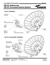
1 Reflector
2 Antenna
Bracket
3 Wall mount bracket
1
4 Fixing
kit
Not supplied in dish package -
LNB, feed clamp and mounting button
Coach screws and nylon plugs
1 – Reflector
2 – Antenna bracket 3 – Wall mount bracket
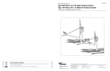
ASSEMBLY INSTRUCTIONS
1. Remove the pre-assembled antenna bracket from
the packaging, pull down the feed leg until the
locking feature clicks positively into place.
2. After determining the correct side appropriate for the
installation rotate the swing arm through 90
°.
S
ecure into position by passing a second M6 x
16mm carriage nut and bolt through the rotation bracket and swing arm from whichever
side is most convenient. These bolts must be only finger tight and will be fully secured
during final alignment.
3. Fit a M6 x 16mm nut and bolt through
the elevation bracket on the most
convenient side for access and fix finger
tight.
4. Fit the Reflector to the Antenna Bracket
by passing the Feed Leg through the
cut out and secure the Reflector to the
Bracket using 4 x M4.8 Crimptite screws
1
1
1

Parts List:
Item Description Quantity
1 Reflector
2 Antenna Bracket
3 Wall mount bracket 1
4 Fixing kit
Not supplied in dish package -
LNB, feed clamp and mounting button
Coach screws and nylon plugs
1 – Reflector
2 – Antenna bracket 3 – Wall mount bracket
ASSEMBLY INSTRUCTIONS
1. Remove the pre-assembled antenna bracket from
the packaging, pull down the feed leg until the
locking feature clicks positively into place.
2. After determining the correct side appropriate for the
installation rotate the swing arm through 90
°.
S
ecure into position by passing a second M6 x
16mm carriage nut and bolt through the rotation bracket and swing arm from whichever
side is most convenient. These bolts must be only finger tight and will be fully secured
during final alignment.
3. Fit a M6 x 16mm nut and bolt through
the elevation bracket on the most
convenient side for access and fix finger
tight.
4. Fit the Reflector to the Antenna Bracket
by passing the Feed Leg through the
cut out and secure the Reflector to the
Bracket using 4 x M4.8 Crimptite screws
1
1
1
5.
Check that the LNB skew setting is appropriate to
the area. To adjust where necessary loosen the
clamp screw and reset to the correct position before
retightening. Angle the front edge of the LNB
Clamp so it locates under the return on top of the
Feed Leg. Whilst supporting the Feed Leg rotate the Clamp down over the Leg ensuring
that the location lugs on the Clamp lock securely into place in the cut outs on the bottom
of the Feed Leg.
6. Remove the mounting button from the Feed
Clamp and push this through the hole on
the top surface of the clamp through into
the feed leg, ensuring that the button sits
firmly on top of the Feed Clamp.
ALIGNMENT PROCEDURE
1. To mount the Antenna to the wall place the Wall Mount
Bracket against the wall at the desired site. Ensure the
rectangular holes are at the bottom and the square holes
at the top. Using a spirit level to ensure the bracket is
perfectly level.
2. Mark and drill holes in the prescribed way and fix the
bracket to the wall using 4 x M8 coach screws and nylon
plugs. Attach the Swing Arm to the bracket and secure in place
using 2 x M6 x 16mm bolts and 2 x M6 Serrated flange nuts.
3. Using a current digital satellite meter align the antenna to the Sky satellites using the approved
procedure. Ensure the antenna face is kept horizontal using the spirit level on the Feed Clamp
assembly, remembering to tighten the two rotation bracket bolts mentioned in Section 2
of the assembly Instructions above.
Note that the spirit level bubble can be viewed from either above or below.
4. Before finalising the installation re-check that the dish face is perfectly level, the LNB is at the
correct skew setting and that signals are optimised. Ensure that all bolts are tightened whilst
maintaining signal optimisation but avoid over tightening as distortion of the dish face or support
assembly will dramatically lower the performance of the dish.

LNB SKEW SETTING:
The 3 zones indicated in the illustration above
correspond to the numbered skew settings on the LNB
casing, only positions 2, 3 and 4 are relevant for the
British Isles.
Quality Installation Guidelines:
1. Do not use the antenna face to make setting adjustments, use the bracketry.
2. Ensure the Wall Mount Bracket is fastened with all 4 bolts, across at least 3 bricks and do not
use the mortar lines. Never fit closer than 3 brick courses from the top of a wall or within 2 brick
widths of an edge.
3. The antenna system must be assembled at the point of installation, do not transport pre-
assembled.
4. Ensure the LNB is at the correct skew setting for the area and the dish face is level and
secure. Always loosen the LNB clamp screw before adjusting the skew.
5. Do not over-tighten the bolts.
Copyright © 2016 TRIAX. All rights reserved. The TRIAX Logo and TRIAX, TRIAX Multimedia
are registered trademarks or trademarks of the TRIAX Company or its afliates.
All specications in this guide are subject to change without further notice.
TRIAX A/S | Bjørnkærvej 3 | DK-8783 Hornsyld | Denmark
triax.com/support
/