Page is loading ...

—
ABB MEASUREMENT & ANALYTICS | OPERATING INSTRUCTION | OI/AWT210-EN REV. C
AWT210
2-wire conductivity, pH/ORP pIon transmitter
Measurement made easy
Introduction
This Operating Instruction provides installation,
operation and maintenance procedures for the
AWT210 2-wire transmitter. The transmitter is fully
compatible with ABB’s range of pH and redox (ORP)
electrodes and with ABB’s range of 2-electrode,
4-electrode and toroidal sensors. The transmitter
has automatic temperature sensor recognition for
Pt100, Pt1000 and 3k Balco RTDs in either 2-lead or
3-lead configurations.
The AWT210 transmitter is available with a
traditional 4 to 20 mA output or with advanced
digital communications utilizing FOUNDATION
Fieldbus (FF), PROFIBUS PA (PA) or HART. The
transmitter is equipped with an LCD display used to
show the current process data and four keys
beneath the display enable the transmitter to be
configured locally.
For more information
Further publications for the AWT210 transmitter
are available for free download from:
www.abb.com/measurement
or by scanning this code:
Links and reference numbers for the transmitter
publications are also shown below:
Search for or click on:
Data Sheet
Commissioning Instruction
Communications Supplement
—
AWT210
2-wire transmitter

2 AWT210 | 2-WIRE CONDUCTIVITY, PH/ORP, PION TRANSMITTER | OI/AWT210-EN REV. C
Sales Service Software
Contents
1 Health & Safety ............................. 4
Document symbols ................................ 4
Safety precautions ................................ 4
Potential safety hazards ........................... 4
damage to the
equipment. ..................................... 4
Safety standards .................................. 4
Product symbols .................................. 4
End-of-life battery disposal ...................5
Information on ROHS Directive 2011/65/EU (RoHS II) .5
2 Cyber security ...............................5
3 Overview....................................6
Name plate/certification label ..................... 6
Transmitters without hazardous area approval . 6
Transmitters with FM/CSA approval and
ATEX IECEx ..................................6
4 Hazardous area considerations ...............7
Approvals ..........................................7
CE Mark ......................................7
Ignition protection ...........................7
Ground ............................................7
Interconnection ....................................7
Power supply for intrinsically safe applications . 7
Configuration ......................................7
Service and repair ..................................7
Risk of electrostatic discharge.................7
Hazardous area relevant information ............... 8
Factory Mutual (FM)...........................8
Canadian Standards Authority (CSA) ...........9
ATEX/IECEx .................................10
Specific conditions of use .........................10
5 Mechanical installation......................11
Sensor installation ................................11
Transmitter installation ............................11
Transmitter dimensions...................... 11
Fitting communication modules .............. 11
Location ....................................11
Optional installation accessories ............. 11
Wall mounting ...............................12
Panel mounting (optional)....................13
Pipe mounting (optional).....................14
6 Electrical installation .......................15
Terminal connections ..............................15
pH/ORP/pIon sensor module connections ..........16
Standard sensors without
diagnostic functions .........................16
Standard sensors with diagnostic functions...16
Conductivity sensor module connections ...........17
2-electrode sensors.......................... 17
4-electrode sensors ......................... 17
Toroidal sensors ............................. 17
Communication module connections ...............18
HART module ................................18
FOUNDATION Fieldbus module ...............18
Profibus PA module ..........................18
Ground connection ................................18
Gland entries ................................18
7 Operation ..................................19
.................19
..................19
Operator menu ................................... 20
Signals View ..................................... 20
8 Diagnostic alarms ..........................21
9 Password security and Access Level ..........23
Access Level ..................................... 23
Write protect switch .............................. 23
Setting passwords ............................... 23
Password recovery ............................... 23
Advanced level password recovery ............23
Service level password recovery ..............23
10 Menu overview ............................ 24
pH menus ........................................ 24
2-electrode conductivity menus ................... 25
4-electrode conductivity menus .................. 26
Toroidal conductivity menus .......................27

AWT210 | 2-WIRE CONDUCTIVITY, PH/ORP, PION TRANSMITTER | OI/AWT210-EN REV. C
3
11 Configuration ............................. 28
Easy Setup ....................................... 28
pH ..........................................28
2-electrode conductivity .....................29
4-electrode conductivity .....................30
Toroidal conductivity ........................31
Calibrate ......................................... 32
pH ..........................................32
2-electrode conductivity .....................33
4-electrode conductivity .....................33
Toroidal conductivity ........................34
Sensor Setup ..................................... 35
pH ..........................................35
2-electrode conductivity .....................36
4-electrode conductivity .....................37
Toroidal conductivity ........................38
Device Setup ..................................... 39
Display .......................................... 39
Input/Output ....................................40
Diagnostics ......................................40
Communication ...................................41
Device Info ........................................41
12 Calibration ................................ 42
pH sensor calibration ............................. 42
Auto Buffer Cal ..............................42
1-point manual calibration....................43
2-point manual calibration ...................43
2-electrode conductivity sensor calibration ........44
4-electrode conductivity sensor calibration ........ 45
Toroidal conductivity sensor calibration ........... 45
PV Zero calibration...........................45
PV Span calibration ..........................46
13 Specification ...............................47
Appendix A – Temperature compensation .......51
Manual and automatic Nernstian temperature
compensation types ...............................51
Solution coefficient compensation type ............51
Appendix B – Upgrading/Reloading............ 52
Factory reset switch .............................. 52
Appendix C – Spare parts ......................53
Communications module assemblies .............. 53
Sensor module assemblies ........................ 53
Main case assemblies ............................. 53
Gland packs ...................................... 53
Glands (packs of 2)...........................53
Blanking plugs...............................53
Mounting kits .................................... 53
Panel-mount kit .............................53
Pipe-mount kit ..............................53
Wall-mount kit...............................53
Weathershield kit ................................. 53
Weathershield kit ............................53
Weathershield and pipe-mount kit ............53

4 AWT210 | 2-WIRE CONDUCTIVITY, PH/ORP, PION TRANSMITTER | OI/AWT210-EN REV. C
1 Health & Safety
Document symbols
Symbols that appear in this document are explained below:
DANGER
The signal word ‘DANGER’ indicates an imminent danger.
Failure to observe this information will result in death or
severe injury.
WARNING
The signal word ‘WARNING’ indicates an imminent danger.
Failure to observe this information may result in death or
severe injury.
CAUTION
The signal word ‘CAUTION’ indicates an imminent danger.
Failure to observe this information may result in minor or
moderate injury.
NOTICE
The signal word ‘NOTICE’ indicates potential material
damage.
Note
‘Note’ indicates useful or important information about the
product.
Safety precautions
Be sure to read, understand and follow the instructions
contained within this manual before and during use of the
equipment. Failure to do so could result in bodily harm or
damage to the equipment.
WARNING
Serious damage to health/risk to life
The AWT210 transmitter is a certified product suitable for
use in hazardous area locations. Before using this product
refer to the product labeling for details of hazardous area
certification. Maintenance and installation and must be
carried out only by the manufacturer, authorized agents or
persons conversant with the construction standards for
hazardous area certified equipment.
Potential safety hazards
AWT210 transmitter – electrical damage to the equipment.
WARNING
Bodily injury.
To ensure safe use when operating this equipment, the
following points must be observed:
• Normal safety precautions must be taken to avoid the
possibility of an accident occurring when operating in
conditions of high pressure and/or temperature.
Safety advice concerning the use of the equipment
described in this manual or any relevant Material Safety
Data Sheets (where applicable) can be obtained from the
Company, together with servicing and spares information.
Safety standards
This product has been designed to satisfy the requirements of
IEC61010-1:2010 3rd edition ‘Safety Requirements for Electrical
Equipment for Measurement, Control and Laboratory Use’ and
complies with US NEC 500, NIST and OSHA.
Product symbols
Symbols that may appear on this product are shown below:
Protective earth (ground) terminal.
Functional earth (ground) terminal.
This symbol, when noted on a product, indicates a
potential hazard which could cause serious personal
injury and/or death. The user should reference this
instruction manual for operation and/or safety
information.
This symbol, when noted on a product enclosure or
barrier, indicates that a risk of electrical shock and/or
electrocution exists and indicates that only
individuals qualified to work with hazardous voltages
should open the enclosure or remove the barrier.
Recycle separately from general waste under the
WEEE directive.

AWT210 | 2-WIRE CONDUCTIVITY, PH/ORP, PION TRANSMITTER | OI/AWT210-EN REV. C
5
Product recycling and disposal
(Europe only)
ABB is committed to ensuring that the risk of any
environmental damage or pollution caused by any of
its products is minimized as far as possible. The
European Waste Electrical and Electronic Equipment
(WEEE) Directive that initially came into force on
August 13 2005 aims to reduce the waste arising from
electrical and electronic equipment; and improve the
environmental performance of all those involved in
the life cycle of electrical and electronic equipment.
In conformity with European local and national
regulations, electrical equipment marked with the
above symbol may not be disposed of in European
public disposal systems after 12 August 2005.
.
NOTICE
For return for recycling, please contact the equipment
manufacturer or supplier for instructions on how to return
end-of-life equipment for proper disposal.
End-of-life battery disposal
The transmitter contains a small lithium battery (located on the
processor/display board) that must be removed and disposed
of responsibly in accordance with local environmental
regulations.
Information on ROHS Directive 2011/65/EU
(RoHS II)
ABB, Industrial Automation, Measurement &
Analytics, UK, fully supports the objectives of the
ROHS II directive. All in-scope products placed on the
market by IAMA UK on and following the 22nd of July
2017 and without any specific exemption, will be
compliant to the ROHS II directive, 2011/65/EU.
2 Cyber security
This product is designed to be connected to and to
communicate information and data via a digital communication
interface. It is your sole responsibility to provide and
continuously ensure a secure connection between the product
and your network or any other network (as the case may be).
You shall establish and maintain any appropriate measures
(such as but not limited to the application of authentication
measures etc.) to protect the product, the network, its system
and the interface against any kind of security breaches,
unauthorized access, interference, intrusion, leakage and/or
theft of data or information.
ABB Ltd and its affiliates are not liable for damages and/or
losses related to such security breaches, any unauthorized
access, interference, intrusion, leakage and/or theft of data
or information.

6 AWT210 | 2-WIRE CONDUCTIVITY, PH/ORP, PION TRANSMITTER | OI/AWT210-EN REV. C
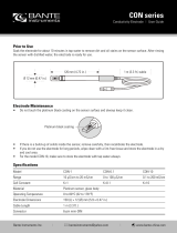
3 Overview
Figure 1 AWT210 transmitter – main components
Name plate/certification label
The following name plates are examples only. The name
plates attached to the transmitter may be different.
Transmitters without hazardous area approval
2809
Transmitters with FM/CSA approval and ATEX IECEx
Aluminium enclosure
APPROVED
US
C
IS : Class I Div 1 ABCD T4,
Class II Div 1 EFG T4
-25
C
≤ Ta ≤
+60
C
Exia
NI: Class 1 Div 2 Gps ABCD
Class II Div 2 Gps FG
Class III
-25
C
≤ Ta ≤
+60
C
FM18US0040X FM18CA0019X
USA: AWT200030 & AWT200031
Canada: AWT200032 & AWT200033
II 1 G Ex ia IIC T4 Ga
-20
C
≤ Ta ≤
+60
C
IP66
FM18ATEX0017X
IECEx FME 18.0001X
Installation drg
AWT2100034
0.56nF Li = 3.3mH
WARNING: SUBSTITUTION OF COMPONENTS
MAY IMPAIR INTRINSIC SAFETY.
AVERTISSEMENT: LA SUBSTITUTION DE
COMPOSANTS PEUT NUIRE À LA SÉCURITÉ
INTRINSÈQUE.
Transmitters with FM/CSA approval and ATEX IECEx
Plastic enclosure
II 1 G Ex ia IIC T4 Ga
-20
C
≤ Ta ≤
+60
C
IP66
FM18ATEX0017X
IECEx FME 18.0001X
Installation drg
AWT200034
IS : Class I Div 1 ABCD T4,
Class II Div 1 EFG T4
-25
C
≤ Ta ≤
+60
C
Exia
FM18US0040X FM18CA0019X
Installation drg:
USA: AWT200030
Canada: AWT200032
FM
0.56nF Li = 3.3mH
WARNING: SUBSTITUTION OF COMPONENTS
MAY IMPAIR INTRINSIC SAFETY.
AVERTISSEMENT: LA SUBSTITUTION DE
COMPOSANTS PEUT NUIRE À LA SÉCURITÉ
INTRINSÈQUE.
Wall mounting
bracket*
Display
Keypad
ON
OFF
Factory reset
switch
Communications module
Transmitter
door lock
Write protect
switch
Sensor module
Tamper-evident seal
attachment point

AWT210 | 2-WIRE CONDUCTIVITY, PH/ORP, PION TRANSMITTER | OI/AWT210-EN REV. C
7
4 Hazardous area considerations
Special regulations must be observed in hazardous areas for
the auxiliary power connection, signal inputs/outputs and
ground connection.
DANGER
• All parts must be installed in accordance with
manufacturer information and relevant standards and
regulations.
• Startup and operation must be performed in accordance
with ATEX User Directive 99/92/EC or BetrSichV
(EN60079-14).
Approvals
CE Mark
The AWT210 transmitter meets all requirements for the CE
mark in accordance with applicable EC Directives 2004/108/EC
(EMC), 2006/95/EC (LVD) and 94/9/EC (ATEX).
Ignition protection
The AWT210 transmitter is available with FM, CSA and ATEX/IEC
approval. Hazardous area relevant information is included later
in this section.
Ground
If for functional reasons, the intrinsically safe circuit must be
grounded by connecting it to an equipotential bonding system,
it must be grounded at a single location only.
Interconnection
Special interconnections, dependent on the safety
requirements, are required when the transmitter is used in
hazardous areas. Proof of interconnection may be required
during the installation if the transmitter is operated in an
intrinsically safe circuit.
Power supply for intrinsically safe applications
The power supply SPS inputs must have corresponding input
protection circuits available to eliminate spark hazards. An
interconnection inspection must be performed. For proof of
intrinsic safety, the electrical limit values must be used as the
basis for the prototype test certificates of the transmitters,
including the capacitance and inductance values of the wires.
Proof of intrinsic safety is granted if the following conditions
are fulfilled.
Output parameter of
power supply/SPS input
Input parameter of
Max. output voltage Uo Ui Max. input voltage
Max. output current Io Ii Max. input current
Max. output power Po Pi Max. input power
Max. output inductance Lo Li+Lc
Internal inductance +
inductance of cable
Max. output capacitance Co Ci=Cc
Internal capacitance +
capacitance of cable
Configuration
AWT210 transmitters can be installed in hazardous areas in
compliance with proof-of-interconnection and directly in a
hazardous area using approved handheld HART/Fieldbus
terminals (proof of interconnection may be required during the
installation) as well as by coupling an ignition-proof modem to
the circuit outside the hazardous area.
Service and repair
DANGER
This product has no live maintenance facility. The
instrument must be de-energized before any maintenance is
performed.
If the instrument is located in a hazardous area, other than the
serviceable items listed in Appendix D, page 60, none of the
instrument’s components can be serviced by the user. Only
personnel from ABB, its approved representative(s) or persons
conversant with the construction standards for hazardous area
certified equipment, is (are) authorized to attempt repairs to
the system and only components formally approved by the
manufacturer should be used. Any attempt at repairing the
instrument in contravention of these principles could cause
damage to the instrument and corporal injury to the person
carrying out the repair. It renders the warranty null and void
and could compromise the hazardous area certification,
correct working of the instrument, electrical integrity and the
CE compliance of the instrument.
If you have any problems with installation, starting or using
the instrument please contact the company that sold it to you.
If this is not possible, or if the results of this approach are not
satisfactory, please contact the manufacturer’s Customer
Service.
Risk of electrostatic discharge
If the instrument is mounted in a hazardous area and the
exterior of the instrument requires cleaning, care should be
taken to minimise the risk of electrostatic discharge. Use a
damp cloth or similar to clean all surfaces.

8 AWT210 | 2-WIRE CONDUCTIVITY, PH/ORP, PION TRANSMITTER | OI/AWT210-EN REV. C
…4 Hazardous area considerations
Hazardous area relevant information
NOTICE
The hazardous area designation is displayed on the name
Factory Mutual (FM)
Intrinsic safety
Class I, Div 1, Group A,B,C,D T4
Class II/III, Div 1, Group E,F,G T4
Figure 2 Intrinsic safety – FM
Maximum voltage Ui =
Maximum input current Ii =
Maximum power Pi =
Internal inductance Li =
Internal capacitance Ci =
Maximum open-circuit voltage Uo =
Maximum short-circuit current Io =
Maximum output power Po =
Maximum inductance Lo =
Maximum capacitance Co =
Maximum open-circuit voltage Uo =
Maximum short-circuit current Io =
Maximum output power Po =
Maximum inductance Lo =
Maximum capacitance Co =
Output parameters of sensor: toroidal
Maximum open-circuit voltage Uo =
Maximum short-circuit current Io =
Maximum output power Po =
Maximum inductance Lo =
Maximum capacitance Co =
Output parameters of sensor: pH
Maximum open-circuit voltage Uo =
Maximum short-circuit current Io =
Maximum output power Po =
Maximum inductance Lo =
Maximum capacitance Co =
Non-incendive
Class I, Div 2, Group A,B,C,D T4
Class II/III, Div 2, Group F,G T4
Figure 3
Figure 4
Ingress protection classification
4X*/I PX6
Ambient temperature range
NOTICE
Parameters apply to entire system inclusive of cables.
Each specified electrical parameter must be applied
individually and in combination. Do not exceed the
maximum values when applying the electrical parameters
individually or in combination.
*4X Hosedown self-assessed not approved by 3
rd
party.
ia
ia
Hazardous area
Div. 1
Transmitter Associated apparatus
providing intrinsically
safe [ia] outputs
Hazardous area
Div. 2
Transmitter Associated apparatus providing
energy limited [nL] or intrinsically
safe [ia] or [ib] outputs
Hazardous area
area
area
Div. 2
Transmitter Power supply

AWT210 | 2-WIRE CONDUCTIVITY, PH/ORP, PION TRANSMITTER | OI/AWT210-EN REV. C
9
Canadian Standards Authority (CSA)
Intrinsic safety
Class I, Div 1, Group A,B,C,D T4
Class II/III, Div 1, Group E,F,G T4
Figure 5 Intrinsic safety – CSA
Maximum voltage Ui =
Maximum input current Ii =
Maximum power Pi =
Internal inductance Li =
Internal capacitance Ci =
Maximum open-circuit voltage Uo =
Maximum short-circuit current Io =
Maximum output power Po =
Maximum inductance Lo =
Maximum capacitance Co =
Maximum open-circuit voltage Uo =
Maximum short-circuit current Io =
Maximum output power Po =
Maximum inductance Lo =
Maximum capacitance Co =
Output parameters of sensor: toroidal
Maximum open-circuit voltage Uo =
Maximum short-circuit current Io =
Maximum output power Po =
Maximum inductance Lo =
Maximum capacitance Co =
Output parameters of sensor: pH
Maximum open-circuit voltage Uo =
Maximum short-circuit current Io =
Maximum output power Po =
Maximum inductance Lo =
Maximum capacitance Co =
Non-incendive
Class I, Div 2, Group A,B,C,D T4
Class II/III, Div 2, Group F,G T4
Figure 6
Figure 7
Ingress protection classification
4X*/I PX6
Ambient temperature range
NOTICE
Parameters apply to entire system inclusive of cables.
Each specified electrical parameter must be applied
individually and in combination. Do not exceed the
maximum values when applying the electrical parameters
individually or in combination.
*4X Hosedown self-assessed not approved by 3
rd
party.
ia
ia
Hazardous area
Div. 1
Transmitter Associated apparatus
providing intrinsically
safe [ia] outputs
Hazardous area
Div. 2
Transmitter Associated apparatus providing
energy limited [nL] or intrinsically
safe [ia] or [ib] outputs
Hazardous area
area
area
Div. 2
Transmitter Power supply
9

10 AWT210 | 2-WIRE CONDUCTIVITY, PH/ORP, PION TRANSMITTER | OI/AWT210-EN REV. C
…4 Hazardous area considerations
…Hazardous area relevant information
ATEX/IECEx
Intrinsic safety
II 1G Ex ia IIC T4 Ga when used with appropriate barriers.
Figure 8 Intrinsic safety – ATEX/IEC
Ingress protection classification
IPX6
Ambient temperature range
Maximum voltage Ui =
Maximum input current Ii =
Maximum power Pi =
Internal inductance Li =
Internal capacitance Ci =
Maximum open-circuit voltage Uo =
Maximum short-circuit current Io =
Maximum output power Po =
Maximum inductance Lo =
Maximum capacitance Co =
Maximum open-circuit voltage Uo =
Maximum short-circuit current Io =
Maximum output power Po =
Maximum inductance Lo =
Maximum capacitance Co =
Output parameters of sensor: toroidal
Maximum open-circuit voltage Uo =
Maximum short-circuit current Io =
Maximum output power Po =
Maximum inductance Lo =
Maximum capacitance Co =
Output parameters of sensor: pH
Maximum open-circuit voltage Uo =
Maximum short-circuit current Io =
Maximum output power Po =
Maximum inductance Lo =
Maximum capacitance Co =
NOTICE
Parameters apply to entire system inclusive of cables.
Each specified electrical parameter must be applied
individually and in combination. Do not exceed the
maximum values when applying the electrical parameters
individually or in combination.
Specific conditions of use
1
see Data Sheet DS/AWT210-EN) contains aluminium and is
considered to present a potential risk of ignition by impact
or friction. Care shall be taken into account during
installation and use to prevent impact or friction.
2
for areas subject to explosive dust atmospheres the painted
surface of the AWT210 may store electrostatic charge and
become a source of ignition in applications with a low
surface is relatively free of surface contamination such as
dirt, dust, or oil. Guidance on protection against the risk of
ignition due to electrostatic discharge can be found in IEC TS
60079-32-1. Cleaning of the painted surface shall only be
done in accordance with the manufacturer’s instructions
(see page 7).
3
for areas subject to explosive gas atmospheres the Lexan
enclosure AWT210 may store electrostatic charge and
become a source of ignition in applications with a low
relatively free of surface contamination such as dirt, dust, or
oil. Guidance on protection against the risk of ignition due to
electrostatic discharge can be found in IEC TS 60079-32-1.
Cleaning of the surface shall only be done in accordance with
the manufacturer’s instructions (see page 7).
4
the AWT210 shall not be used where UV light or radiation
may impinge on the enclosure or the window of the
enclosure.
5 only
in non-flammable materials.
ia
ia
Hazardous area
Zone 2
Transmitter Associated apparatus
providing intrinsically
safe [ia] outputs

AWT210 | 2-WIRE CONDUCTIVITY, PH/ORP, PION TRANSMITTER | OI/AWT210-EN REV. C
11
5 Mechanical installation
Sensor installation
Refer to the sensor’s Operating Instruction for installation
procedures.
Transmitter installation
Transmitter dimensions
Dimensions in mm (in)
Figure 9 Transmitter dimensions
Fitting communication modules
Referring to Figure 10:
1 Ensure the locking spindle on both modules is in the
UNLOCKED position.
2 Fit communication module A to baseboard B
(the left, COMMUNICATION MODULE position).
3 Turn the locking spindle ¼ turn to the LOCKED position.
4 Fit sensor module C to baseboard D
(the right, SENSOR MODULE position).
5 Turn the locking spindle ¼ turn to the LOCKED position.
Figure 10 Fitting communication modules
Location
For general location requirements refer to Figure 11. Select a
location away from strong electrical and magnetic fields. If this
is not possible, particularly in applications where mobile
communications equipment is expected to be used, screened
cables within flexible, earthed metal conduit must be used.
Install in a clean, dry, well ventilated and vibration-free location
providing easy access. Avoid rooms containing corrosive gases
or vapors, for example, chlorination equipment or chlorine gas
cylinders.
Figure 11 Transmitter location
Optional installation accessories
• Cable gland kit
• Panel-mount kit
• Pipe-mount kit
• Weathershield
144 (5.67)
10
(0.39)
55
(2.16)
99 ( (3.89)
73 ( (2.87)
144
(5.67)
16
(0.63)
COMMUNICATION
MODULE
SENSOR
MODULE
LOCKED UNLOCKED
Max. cable distance
transmitter to sensor
(refer to sensor
Operating Instruction)
non-condensing
Ambient temperature
Humidity
min.
max.

12
AWT210 | 2-WIRE CONDUCTIVITY, PH/ORP, PION TRANSMITTER | OI/AWT210-EN REV. C
…5 Mechanical installation
…Transmitter installation
Wall mounting
Referring to Figure 12:
1 Position the left- and right-hand mounting brackets A into
the recesses on the rear of the transmitter as shown and
secure with the bracket securing screws. Ensure the plastic
washers remain in the positions fitted.
2 Mark fixing centers B and drill suitable holes in the wall.
3 Secure the transmitter to the wall using 2 screws C in
each mounting bracket.
NOTICE
If the optional weathershield D is used, position it between
the transmitter and wall and pass 2 screws C through
fixing holes (both sides) in weathershield.
Dimensions in mm (in)
A
B
C
right hand bracket omitted
for clarity
62
(2.44)
152 (5.98)
Weathershield dimensions
Optional weathershield
209 (8.22)
175 (6.89)
200
(7.87)
Figure 12 Wall mounting the transmitter

AWT210 | 2-WIRE CONDUCTIVITY, PH/ORP, PION TRANSMITTER | OI/AWT210-EN REV. C
13
Panel mounting (optional)
Referring to Figure 13:
1 Cut the correct sized hole in panel A.
2 Insert the transmitter into the panel cut-out B.
3 Screw one panel clamp anchor screw C into the left-hand
bracket D until 10 to 15 mm (0.39 to 0.59 in) of the thread
protrudes from the other side of the bracket and position
one clamp E over the end of the thread.
NOTICE
The correct torque is critical to ensure proper compression
of the panel seal and achieve the IPX6/NEMA 4X hosedown
6.
Dimensions in mm (in)
4 Holding assembly F together, position bracket D into the
left-hand recess on the rear of the transmitter and secure
with bracket securing screw G. Ensure that the plastic
washer remains in the position fitted.
5 Repeat steps 3 and 4 for the right-hand panel clamp
assembly.
6 Torque each panel clamp anchor screw to 0.5 to 0.6 Nm
(4.42 to 5.31 lbf/in).
Figure 13 Panel mounting the transmitter
A
B
C
D
E
F
A
G
max. thickness
6 (0.24)
Gasket
Panel cut-out dimensions
30 (1.2)
73 (2.87)
25.5
(1.00)
138
+1.0
+0.04
(5.43 )
138
+1.0
+0.04
(5.43 )
30
(1.2)

14 AWT210 | 2-WIRE CONDUCTIVITY, PH/ORP, PION TRANSMITTER | OI/AWT210-EN REV. C
…5 Mechanical installation
…Transmitter installation
Pipe mounting (optional)
Referring to Figure 14, secure the transmitter to a pipe as
follows:
1 Fit two M6 x 50 mm hexagon-head screws A through one
clamp plate as shown.
2 Using the appropriate holes to suit vertical or horizontal
pipe, secure the clamp plate to the pipe-mounting bracket
B using two M6 x 8 mm hexagon-head screws and spring
lock washers C.
3 Position the pipe mounting bracket into the recesses on the
rear of the transmitter as shown and secure with the two
bracket securing screws D . Ensure the plastic washers
remain in the positions fitted.
4 Secure the transmitter to the pipe using the remaining clamp
plate, spring lock washers and nuts E.
Dimensions in mm (in)
NOTICE
If the optional weathershield F is used, locate it against
the transmitter back panel and attach the pipe-mount kit to
the weathershield rear face and transmitter.
A
C
D
E
C
B
B
E
Vertical
pipe
Horizontal
pipe
Pipe diameters:
max. 62 (2.44)/min. 45 (1.77)
Weathershield
(see page 12 for dimensions)
If weathershield is used, attach
mounting bracket to rear face
Figure 14 Pipe mounting the transmitter

AWT210 | 2-WIRE CONDUCTIVITY, PH/ORP, PION TRANSMITTER | OI/AWT210-EN REV. C
15
6 Electrical installation
DANGER
• If the transmitter is used in a manner not specified by the
Company, the protection provided by the equipment may
be impaired.
• Refer to page 7 for electrical installation
considerations in Hazardous areas.
• The transmitter conforms to Installation Category II of IEC
61010.
• All equipment connected to the transmitter’s terminals
must comply with local safety standards (IEC 60950,
EN61010-1).
DANGER – CONNECTION/CABLE
REQUIREMENTS
• The connection terminals accept cables with peripheral
wire cross-section of:
min.: 0.14 mm
2
(26 AWG)
max.: 1.5 mm
2
(14 AWG)
• Do not use a rigid conductor material as this can result in
wire breaks.
• Ensure the connecting cable is flexible.
• To ensure the sensor cable length is sufficient, allow an
additional 100 mm (4 in) of cable to pass through cable
glands into the housing.
• Ensure the correct connections are made to suit the
transmitter variant.
Terminal connections
Figure 15 Connections overview
123
4
5
123
4
5
AB AB
–+–+
123
4
5
6
7
8
Power Ammeter
SENSE
GUARD
RTD 1
RTD 2
SHIELD
RTD 3
REF
SOL_GND
12345678
12345678
12345678
DRIVE +
DRIVE –
RTD 1
RTD 2
SHIELD
RTD 3
DRIVE +
DRIVE –
RTD 1
RTD 2
SHIELD
RTD 3
SENSE +
SENSE –
DRIVE +
DRIVE –
RTD 1
RTD 2
SHIELD
RTD 3
SENSE +
SENSE –
Communication module connections
Sensor module connections
HART modules
HART modules
2-electrode conductivity modules
4-electrode conductivity modules
Toroidal conductivity modules
pH/ORP/plon modules

16
AWT210 | 2-WIRE CONDUCTIVITY, PH/ORP, PION TRANSMITTER | OI/AWT210-EN REV. C
…6 Electrical installation
pH/ORP/pIon sensor module connections
NOTICE
ORP (Redox) and Antimony pH sensors do not feature
temperature compensation therefore do not have
temperature sensors or related wiring.
Standard sensors without diagnostic functions
NOTICE
Ensure sensor diagnostics are Off when using standard
sensors without diagnostic functions.
Sensor type RTD wiring
SENSE
GUARD
REF
S.GND
SHIELD
Clear Black Red White
Blue Black Red White
Clear Black
Red
Red
White
Clear Black White Red Red
Blue Black Red White
Blue Black Red White Grey
Blue Yellow Black Red White
Blue Yellow Black Red White Grey
* Cut and remove grey wire
Standard sensors with diagnostic functions
NOTICE
Ensure sensor diagnostics are On when using standard
sensors with diagnostic functions.
Sensor type RTD wiring
SENSE
GUARD
REF
S.GND
SHIELD
Blue Yellow Black Green Red White Dark green
Clear Red Blue Green/Yellow Red White
Clear Red Blue Green/Yellow Red White Grey
* Cut and remove grey wire
NOTICE
AWT210 pH sensor modules are supplied standardized to
theoretical sensor characteristics. Following installation,
but before use, a process calibration should be performed
to ensure optimum accuracy. For pH sensor calibration
procedures see page 42.
NOTICE
BNC adaptor option
For pH/ORP/pION sensors using a BNC connector, ABB
recommends using the optional BNC adapter.
ABB does not recommend stripping or cutting sensor
cabling due to the nature of the signal and cabling used.

AWT210 | 2-WIRE CONDUCTIVITY, PH/ORP, PION TRANSMITTER | OI/AWT210-EN REV. C
17
Conductivity sensor module connections
2-electrode sensors
Sensor type RTD wiring
DRIVE +
DRIVE –
SHIELD
Red Black
Green/
Yellow Blue
Brown
Red Black Brown
Green/
Yellow
Blue
Green Black Blue Yellow Dark green
Green Black Blue/Red Yellow Dark green
Green Black Yellow Red Dark green Blue
NOTICE
AWT210 2-electrode conductivity sensor modules are supplied
standardized to theoretical sensor characteristics. Following
installation, but before use, a process calibration should be
performed to ensure optimum accuracy. For 2-electrode
conductivity sensor calibration procedures see page 44.
4-electrode sensors
Sensor type RTD wiring
DRIVE +
SENSE +
SENSE –
DRIVE –
SHIELD
Green Red White Black Blue Yellow Dark green
NOTICE
AWT210 4-electrode conductivity sensor modules are supplied
standardized to theoretical sensor characteristics. Following
installation, but before use, a process calibration should be
performed to ensure optimum accuracy. For 4-electrode
conductivity sensor calibration procedures see page 45.
Toroidal sensors
Sensor type RTD wiring
DRIVE +
DRIVE –
SENSE +
SENSE –
SHIELD
Black Blue White Red Green Yellow Dark green
NOTICE
AWT210 toroidal conductivity sensor modules are supplied
standardized to theoretical sensor characteristics. Following
installation, but before use, a process calibration should be
performed to ensure optimum accuracy. For toroidal
conductivity sensor calibration procedures see page 45.

18 AWT210 | 2-WIRE CONDUCTIVITY, PH/ORP, PION TRANSMITTER | OI/AWT210-EN REV. C
…6 Electrical installation
Communication module connections
HART module
FOUNDATION Fieldbus module
Profibus PA module
Ground connection
Normal grounding practice is to terminate all grounds at the
control room side, in which case the field side of the screen
should be adequately protected to avoid contact with metallic
objects. The transmitter case should be grounded.
WARNING
Bodily injury
If conduit hubs are used, they will not provide a bonding of
the enclosure or system.
Referring to Figure 16, ground connections are provided:
internally A and externally B.
Figure 16 AWT210 ground connections
For IS systems the grounding should be at the safety barrier
earth connection. For bus-powered systems the grounding of
the screen should be close to the power supply unit. The
specific noise immunity and emitted interference are only
ensuring that screening is maintained through any existing
junction boxes. Appropriate equipotential bonding must be
provided to avoid differences in potential among the individual
plant components.
To ensure fault-free communication on Fieldbus (FF or PA)
installations, the bus must be properly terminated at both
ends. Only approved bus terminators must be used for
intrinsically safe circuits.
NOTICE
HART, Profibus and Fieldbus protocols are not secure.
Therefore, the intended application should be assessed
before implementation to ensure these protocols are
suitable.
Gland entries
For hazardous area installations, suitable Ex glands and
blanking elements must be used to seal the entry holes.
+–
2
+–
1435
Power
Non IS installations
12 to 42 V DC
IS installations
12 to 30 V DC
Functional earth
Ammeter connection for loop current test
Ammeter
AB
2
AB
1435
Connected internally
Non IS installations
9 to 32 V DC
IS installations
9 to 24 V DC
Functional earth
AB
2
AB
1435
Connected internally
Non IS installations
9 to 32 V DC
IS installations
9 to 24 V DC
Functional earth

AWT210 | 2-WIRE CONDUCTIVITY, PH/ORP, PION TRANSMITTER | OI/AWT210-EN REV. C
19
7 Operation
Operator Page – normal conditions
Figure 17 Example Operator pages – normal conditions
Operator Page – alarm conditions
If any of the diagnostic alarms are active the NAMUR status of the device is indicated by displaying the class
and category of the highest priority active alarm.
Figure 18 Example Operator pages – alarm conditions
Read Only
Calibrate
Advanced
Service
Write Protected
Access level Process values
Operator pages can be
configured independently
to display:
Calibration
page
Operator
menu
PV
HART Tag (HART devices) or Tag Descriptor (FF and PA devices)
PV + temperature
PV + temperature + OP
(HART devices only
Failure
Check Function
Off Specification
Maintenance Required
Alarm class
Alarm category
Calibration
page
Operator
menu
Process

20 AWT210 | 2-WIRE CONDUCTIVITY, PH/ORP, PION TRANSMITTER | OI/AWT210-EN REV. C
…7 Operation
Operator menu
From the Operator menu, use the keys to highlight the
required menu and press the key to select:
Operator menus comprise:
• Diagnostics: displays a list of active diagnostic alarm
• Configuration: enters the Configuration level menus
page 28.
• Operator Page 1: displays the first Operator Page.
• Operator Page 2: displays the second Operator Page
(available only if Operator Page 2 enabled).
• Autoscroll: switches automatically between the two
Operator pages (available only if Operator Page 2 enabled).
• Signals View: displays a list of active signals.
Signals View
Operator Menu
Operator Page 1
Operator Page 2
Autoscroll
Signals view
Diagnostics
Conguration
Back Select
Signals View
PV 7.33 pH
SV 25.0 °pH
TV 37 KW
QV 1.06 mV
PV% 12.4 %
Back Exit
Signal
Sensor type
pH
Sensor type
Sensor type
Sensor type
toroidal conductivity
PV pH, ORP, Ion Conc or pION Conductivity or Concentration Conductivity or Concentration Conductivity or Concentration
SV Temperature Temperature Temperature Temperature
TV Reference impedance
Conductivity without
temperature compensation
Conductivity without
temperature compensation
Conductivity without
temperature compensation
QV pH, Cell output (mV) Conductivity Conductivity Conductivity
Primary variable percentage
of engineering range
Primary variable percentage
of engineering range
Primary variable percentage
of engineering range
Primary variable percentage
of engineering range
O/P
Current output
(HART versions only)
Current output
(HART versions only)
Current output
(HART versions only)
Current output
(HART versions only)
Table 1 Signals View/Sensor type values displayed
/