Page is loading ...

X1 Lock
X2 Shims(Small)
X2 Shims(Large) X2 Templates
6PIN Connector
X1 Strike plate
X1 Faceplate
Screws Accessories:
X 8 Screws 4 x 8 mm
X 4 Screws 5 x 8 mm
X 4 Screws 4 x 15 mm
X 2 Screws 5 x 26 mm
Specifications
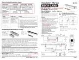
SL-133 DEADBOLT LOCK INSTALLATION MANUAL
Power Supply
Current
Operation Delay Time
Signal Output
Face Plate
Strike Plate
Bolt
Safety Measures
160(L) X 25 (W) X 34.5 (H) mm
90 (L) X 23 (W) X 2.5 (H) mm
16mm (Throw) X 12.7mm (Diameter)
(1)Fail-safe Type (Power to lock).
(2)Built-in photo couplers door open push button input contact. Door will lock
again automatically when door is not open within 5 seconds.
DC 12V / 1A
Operation Current : 880mA Holding Current :160mA
0sec.3sec.(adjustable by user)
N.C N.O(250mA) Dry contact
Connections
Wiring Diagram
Reader
Push Button
Orange
Brown
Red
Page 1
Brown
Orange
Red
-GND
+DC12V
Push Button
6-PIN
Color Model
Yellow
Green
Blue
Door Position Sensor (N.C)
Door Position Sensor (COM)
Door Position Sensor (N.O)
Setting door lock delay timer
0Sec 3Sen
(Default)
AP-10
DC 12V
1A
Accessories
N.C
N.O
COM
When door is not closed,
detection output is COM
and N.O. Connected.
When door is closed,
detection output is COM
and N.C. Connected.
N.O.
N.C.
COM
N.O.
N.C.
COM
N.O.
N.C.
COM
Please switch on the appliance again to validate any adjustment of DIP switch value.
Lock Control - Zwaluwstraat 132 - 1840 Malderen - Belgium - Tel. +32 52 57 43 02 - [email protected] - www.lockcontrol.be
Lock Control - Kouterbaan 63 - 1840 Malderen - Belgium - Tel. +32 52 57 43 02 - [email protected] - www.lockcontrol.be

35
140
161
26
14.5
M5
24
M4
12
91
76
7.5
21
112
Page 2
If delay time of 3 seconds
Current and Temperature Chart
600
500
400
300
200
100
012345678910 11 12 13
60
50
40
30
20
010 20 30 40 50 60 70 80 90 100 110 120 130 140 150
Current
(mA)
Start
Door Close
Door Lock
Delay Timer Stand-by
Time(Sec) Time(Sec)
Door closed when power is on.
(Measurement:Power Supply DC-12V.
Room temperature 30 , Humidity 60% Rh)
Temperature
C
900
800
700
Hollow metal door Wooden door
Installation Diagram
Hollow metal door
The lock is hot.
The unlock operation temperature of the lock is normally within 48
(Please refer to Page2 Current and Temperature Chart).
No operation after installation.
1.Please check power supply.
2.Turn in on again and press push button.
3.Please make sure to place strike plate on the lock and aim the bolt hole with the bolt. Please make
sure the position of the magnet is right before testing the electric lock.
Lock did not function when the door is shut.
1.Please check power supply(12V/1A).
2.Please check if the direction and position of strike plate is bing installed correctly.
3.Please check the connection points(N.O or N.C.).
Wires facing
downward.
Unit:mm
Lock Control - Kouterbaan 63 - 1840 Malderen - Belgium - Tel. +32 52 57 43 02 - [email protected] - www.lockcontrol.be
/