Page is loading ...

Model No: ABX350M
UPRIGHT
BIKE
Retain this owner’s manual for future reference.
Read and follow all instructions in this owner’s manual.
Version A

Step 1
Visit our Website
Go to the GPI Sports website: www.gpisports.com.au/warranty
Warranty Registration Form
Step 2
Enter Purchase Information
Enter all purchase information including the serial number and proof
of purchase which can be uploaded from this page
Step 3
Call Our Toll Free Number
If a warranty service request is required on your product
please call the toll free number - 1800 005 770
Congratulations on purchasing your product, we at GPI believe that our product range is of the
highest quality and represents great value for money.
We back our product range up with our industry leading warranty.
Please see below for the step by step instructions on how to register your product warranty
online.
GPI Sports & Fitness

1
Dear Customer,
Please read this instruction very carefully before using the item.
http://www.ustylesports.com/
IMPORTANT SAFETY NOTICE:
Note the following precaution before assembling or operating the machine
1、 Assemble the machine exactly as the descriptions in the instruction
manual.
2、 Check all the screws, nuts and other connections before using the machine
for the first time and ensure that the trainer is in a safe condition.
3、 Set up the machine in a dry level place and place it away from moisture
and water.
4、 Place a suitable base (e.g. rubber mat, wooden board etc.) beneath the
machine in the area of assembly to avoid dirt and etc.
5、 Before beginning training, remove all objects within a radius of 2 meters
from the machine.
6、 Do not use aggressive cleaning articles to clean the machine, only use the
supplied tools or suitable tools of your own to assemble the machine or
repair any parts of machine. Remove drops of sweat from the machine
immediately after finishing training.
7、 Your health can be affected by incorrect or excessive training. Consult a
doctor before beginning a training program. He can define the maximum
setting (Pulse, Watts, Duration of training etc.) to which you may train
yourself and can get precise information during training. This machine is
not suitable for therapeutic purpose.
8、 Only do training on the machine when it is in correct working order. Use
only original spare parts for any necessary repairs.
9、 This machine can be used for only one person’s training at a time.
10、 Wear training clothes and shoes, which are suitable for fitness training with
the machine. Your training shoes should be appropriate for the trainer.
11、 If you have any feeling of dizziness, sickness or other abnormal symptoms,
please stop training immediately and consult a doctor as soon as possible.

2
12、 People such as children and handicapped persons should only use the
machine in the presence of another person who can give aid and advice.
13、 The power of the machine increases with the increasing of speed, and the
reverse. The machine is equipped with adjustable knob, which can adjust
the resistance. Reduce the resistance by turning the adjusting knob for the
resistance setting towards stage 1. Increase the resistance by turning the
adjusting knob for the resistance setting towards stage 8. The maximum
user’s weight is 130kg/286.6lbs.
14、 Care must be taken when lifting or moving the equipment so as not to injure
your back. Always use proper lifting techniques and/or use assistance.

3
EXPLODED VIEW & PARTS LIST:

4
NO
NAME
QUA.
NO
NAME
QUA.
1
Computer
1
37
Seat post plastic cover
1
2
Bolt M5*10
5
38
D bushing
1
3
End cap Φ25
2
39
Spring knob M16
1
4
Handlebar(L)
1
40L/R
Pedal
各 1
5
Handlebar(R)
1
41L/R
Crank 170
各 1
6
Foam
2
42
Crank cover
2
7
Screw ST4.2*19
18
43
Nut M10*1.25
2
8
Pulse Φ25
2
44
Chain cover molding
2
9
Bolt M8*16
20
45L/R
Chain cover
各 1
10
washer d8*Φ20*1.5
23
46
Snap ring d17
2
11
Handlebar wire
2
47
Bearing 6203
2
12
Tension knob
1
48
Belt pulley
1
13
Screw M5*35
1
49
Axle
1
14
Arc Washer d6
1
50
Belt
1
15
Support tube
1
51
Bolt M6*15
4
16
Middle wire
1
52
Nylon nut M6
4
17
Front stabiliser
1
53
Pinch roller
1
18
End cap L
1
54
Screw
1
19
End cap R
1
55
Tension spring
1
20
Rear stabiliser
1
56
Nut M10*1.0
2
21
End cap L
1
57
Bolt group
2
22
End cap R
1
58
Hexagon thin nut M10*1.0
2
23
Front plastic cover
1
59
U bracket
2
24
Tension line
1
25
Sensor line
1
26
Main frame
1
27
Seat
1
28
Seat tube
1
Open-end wrench S13-14-15
1
29
Stopper F38*38
2
Allen wrench S6
1
30
Flywheel
1
31
Plastic cover
1
32
Vertical seat post
1
33
Nylon nut M8
5
34
U bracket
1
35
Washer D10*Φ20*2
3
36
Knob M10
1

5
HARDWARE PACKS:
9# M8*16 20PCS
10# d8*Φ20*1.5 23PCS
36# M10 1PC
39# M16 1PC
33# M8 3PCS
35# d10* 20*2 1PC
2# M5*10 5PCS
S13-S14-S15
S6

6
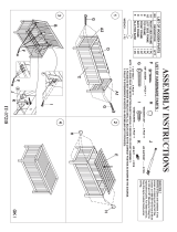
ASSEMBLY INSTRUCTION
STEP 1:Attach the front stabiliser (17) and the rear stabiliser (20) to the main frame (26) with bolt (9)
and washer (10); Attach the pedal (40L/R) to the crank arms as shown in FIG.1, CAUTION: be sure
the right pedal (40R) marked (R) is attached to the right crank arm and tightened in the clockwise
direction. The left pedal (40L) marked (L) is attached to the left crank arm and tightened in the
anticlockwise direction.
S15
9# M8*16 8PCS
10# d8*Φ20*1.5 8PCS
STEP 2:
Put the front plastic cover (23) to the support tube (15), then connect the sensor 16 & 25 and tension
control wire 12 & 24 as shown in FIG.3, and install the support tube (15) on the main frame (26) with
bolt (9) and washer (10).
9# M8*16 8PCS
10# d8*Φ20*1.5 8PCS
12
24

7
STEP 3:
Attach the seat (27) to the seat tube (28) with washer (10) and nylon nut (33), then tighten seat (27).
Slide the seat tube (28) into the vertical seat post (32) and at the desired position, align the holes and
fix in place with the locking knob (36) and washer (35). Insert the vertical Seat Post (32) into the main
frame (26) and line up the holes. Secure the seat in position with the adjustment knob (39). The
correct height for the seat can be adjusted after the bike is fully assembled.
33# M8 3PCS
10# d8* 20*1.5 3PCS
35# d10* 20*2 1PC
36# M10 1PC
39# M16 1PC
2# M5*10 1PC
STEP 4:
Attach the handlebar (4 & 5) to the support tube (15) with the screw (9) and washer (10). Connect the
sensor as shown in FIG.4, then Install the computer (1) into the support tube (15) with the bolt (2).
9# M8*16 4PCS
10# d8*Φ20*1.5 4PCS
2# M5*10 4PCS
S15

8
CAUTION: MAKE SURE YOU HAVE TIGHTENED ALL THE BOLTS AND NUTS WELL BEFORE
BEGINNING YOUR WORKOUT.
NOTE: THE END CAP ON THE FRONT STABILISER TUBE IS MOVABLE, WHICH IT IS EASY
FOR YOU TO MOVE YOUR TRAINING BIKE, AND THE END CAP ON THE REAR STABILISER
CAN ADJUST THE PARALLELISM.
EXERCISE INSTRUCTIONS
1.The Warm Up Phase
STOP.
2.The Exercise Phase
SIDE BENDS OUTER THIGH
INNER THIGH
FORWARD
BENDS
CALF / ACHILLES

9
3. The Cool Down Phase
MUSCLE TONING
WEIGHT LOSS
USE
The tension control knob allows you to alter the resistance of the pedals. High resistance makes
it more difficult to pedal, a low resistance makes it easier. For the best results set the tension
while the bike is in use.
This stage should last for a minimum of 12 minutes though, most people
start at about 15-20 minutes

10
EXERCISE MONITOR INSTRUCTION MANUAL
SPECIFICATIONS:
TIME……………………………………………………………….00:00-99:59
SPEED (SPD).……………………………………………0.0-99.9KM/H (ML/H)
DISTANCE………………………………………………....0.00-9999KM (ML)
CALORIES………………………………………………….......0.0-9999KCAL
※ODOMETER(ODO)…………………………..…………..…0.0-9999KM (ML)
※RPM…………………………..…………..……………………………...0-9999
※PULSE (PUL) …….....................................................................0, 40~240BPM
KEY FUNCTIONS:
MODE: This key lets you to select and lock on to a function you want.
※SET: Can to proceed the data establish for TIME、DISTANCE、CALORIES、PULSE.
CLEAR (RESET): The key to reset the value to zero by pressing the key.
※ON/OFF (START/STOP): The key to pause the signal input by pressing the key.
OPERATION PROCEDURES:
1. AUTO ON/OFF:
The system turns on when any key is pressed or when it sensor an input from the
speed sensor.
The system turns off automatically when the speed has no signal input or no key
are pressed for approximately 4 minutes.
2. RESET: The unit can be reset by either changing battery or pressing the MODE key
for 3 seconds.
3. MODE: To choose the SCAN or LOCK if you do not want the scan mode, press the
MODE key when the pointer on the function you want which begins blinking.
FUNCTIONS:
1. TIME: Press the MODE key until pointer lock on to TIME. The total working time will
be shown when starting exercise.
2. SPEED: Press the MODE key until the pointer advance to SPEED. The current speed
will be shown.
3. DISTANCE: Press the MODE key until the pointer advance to DISTANCE. The
distance of each workout will be displayed.
4. CALORIE: Press the MODE key until pointer lock on to CALORIE. The calorie burned
will be displayed when starting exercise.
5. ODOMETER (IF HAVE): Press the MODE key until the pointer advance to
ODOMETER. The total accumulated distance will be shown.
6. RPM (IF HAVE): Measure the average number of times.
7. PULSE (IF HAVE): Press the MODE key until the pointer advance to PULSE .User’s
current heart rate will be displayed in beats per minute. Place the palms of your
hands on both of the contact pads (or put ear-clip to ear),and wait for 30 seconds for
the most accurate reading.
SCAN: Automatically display changes every 4 seconds.
BATTERY:If improper display on monitor, please reinstall the batteries to achieve a
good result.

Model No: KR6000PRO
To register your warranty, please go to
www.gpisports.com.au
PROGRAMMABLE ROWER
UPRIGHT BIKE
Model No: ABX350M
/