Page is loading ...

SERVICE
MANUAL
SUPPLEMENT
DIESEL ENGINE
REAR
WHEEL
DRIVE
TRUCK
D&
W
250-350

TYSLER
MOTTOES
DIESEL
ENGINE
SERVICE
MANUAL
SUPPLEMENT
1991
1/2
DODGE
TRUCKS
NO PART
OF
THIS PUBLICATION MAY
BE
REPRODUCED, STORED
IN A
RETRIEVAL
SYSTEM,
OR
TRANSMITTED,
IN ANY FORM
OR
BY ANY
MEANS, ELECTRONIC,
ME-
CHANICAL,
PHOTOCOPYING, RECORDING,
OR OTHERWISE WITHOUT
THE
PRIOR
WRITTEN
PERMISSION
OF
CHRYSLER
MOTORS.
To
order
the
special
service
tools
used and
illustrated,
please
refer
to the
instructions
on
inside
back
cover.
Chrysler
Motors
reserves the
right
to make changes in design or to make
additions to or improvements in its products
wihtout
imposing any obliga-
tions upon itself to install
them
on its products previously manufactured.
Litho
in
U.S.A.
Copyright ©1991
Chrysler
Motors
20M191

FOREWORD
The information contained in this service manual has
been
prepared for the professional automotive techni-
cian
involved in daily repair operations. This manual
does
not cover theory of operation,
which
is
addressed
in
service training material.
Information
in this manual is divided into groups.
These
groups contain general information, diagnosis,
test-
ing,
adjustments, removal, installation, disassembly, and assembly
procedures
for the components.
To
assist
in locating a group
title
page,
use the Group Tab Locator on the
following
page.
The
solid
bar after
the group
title
is aligned to a
solid
tab on the
first
page
of
each
group. This
first
page
of the group has a
contents section that lists major topics
within
the group.
Chrysler Motors
reserves
the
right
to
change
testing procedures, specifications, diagnosis, repair methods, or
vehicle
wiring
at any time without prior notice or incurring obligation.
Information
describing the operation and use of standard and optional equipment is included in the Owner's
Manual
provided
with
the vehicle.

C01P01E1T
Ali SYSTEi INDEX
Name
Group-page
5.9L DIESEL
ENGINES.
.
.... 9-1
ENGINE
DIAGNOSIS
9=3
ENGINE
SERVICE
PROCEDURES
9-12
GENERAL
INFORMATION
-.9-1
AIR
CONDITIONING
24-1
COMPRESSOR
OVERHAUL
(SD-709)
........ 24-1
Compressor
24-2
Compressor
Isolation
24-1
Compressor
Shaft Seal 24-5
Cylinder
Head/Valve
Plate
24-8
Description
24-1
Magnetic
Clutch 24-2
Purging
Compressor
of Air 24-1
TORQUE
SPECIFICATIONS—A/C
COMPRESSOR
24-9
BRAKES............
.......5-1
Diesel
Vacuum
Pump
.5-1
Installing
Vacuu,—Steering
Pump
Assembly
5-5
Low
Vacuum
Warning
Switch 5-1
Pump
Adapter
Replacement
5-4
Removing
Vacuum—Steering
Pump
Assembly
5-2
Vacuum
Pump
Diagnosis 5-2
Vacuum
Pump
Operation 5-1
Vacuum
Pump
Replacement
5-4
Vacuum
Pump
Serviceability
5-1
COOLING
SYSTEM
7-1
SPECIFICATIONS
7-1
EMISSION
CONTROL
SYSTEMS
25-1
EXHAUST
EMISSION
CONTROLS
25-1
EXHAUST
SYSTEM
AND
INTAKE
MANIFOLD.
.... 11-1
SERVICE
PROCEDURES
(DIESEL
ENGINES)
.
.
. 11-1
Exhaust Manifold 11-1
Intake
Manifold Cover/Air Intake Heater 11-2
Intercooler
.11-8
Turbocharger 11-3
SPECIFICATIONS
11-9
FUEL
SYSTEM
14-1
DIESEL
FUEL
INJECTION
14-1
Air
Intake Heater Relays—Engine
Controller
Output
14-4
Battery
Voltage—Engine
Controller
Input .. . 14-2
Brake
Switch—Engine
Controller
Input .... 14-2
Charge
Air
Temperature
Sensor—Engine
Controller
Input 14-2
Crank
Signal—Engine
Controller
Input 14-2
Engine
Controller
14-1
General Information 14-1
Name
Group-page
Ignition
Sense—Engine
Controller
Input 14-2
KSB Solenoid 14-5
Overdrive Override
Switchitch
—Engine
Controller
Input 14-2
Overdrive Solenoid—Engine
Controller
Output
14-5'
Park/Neutral Switch —Engine
Controller
Input 14-2
SCI Receive and SCI Transmit—Engine
Controller
Output
14-5
Speed
Control—Engine
Controller
Input .... 14-3
Speed
Control—Engine
Controller
Output
... 14-5
System
Diagnosis 14-1
System
Operation 14-5
Throttle
Position
Sensor (TPS)—Engine
Controller
Input 14-3
Vehicle
Distance (Speed) Sensor—Engine
Controller
Input 14-3
Wait-To-Start
Lamp—Engine
Controller
Output
14-5
Water-ln-Fuel
Lamp—Engine
Controller
Output
. 14-5
Water-ln-Fuel Sensor—Engine
Controller
Input 14-3
GENERAL
DIAGNOSIS-DIESEL
. 14-8
Air
Intake Heater 14-11
KSB Solenoid 14-11
On
Board
Diagnostics 14-11
Throttle
Position
Sensor Test 14-10
Visual
Inspection 14-8
SERVICE
PROCEDURES
14-21
Fuel
Injection
Pump
14-22
Injection
Timing
14-26
KSB Solenoid 14-22
Throttle
Position
Sensor 14-21
INSTRUMENT
PANEL
AND
GAUGES
8E-1
SPEED
CONTROL
SYSTEM
8H-1
SERVICE
PROCEDURES
8H-8
TEST
PROCEDURES
8H-4
Checking for
Fault
Code
8H-4
Distance
(Speed) Sensor Test 8H-4
Inoperative
System
8H-4
Road
Test 8H-4
Speed
Control Cable
Attachment—Engine
.. 8H-7
Speed
Control Cable
Attachment—Servo
... 8H-7
Speed
Control Switch Test 8H-5
Speed
Control
System
Electrical
Tests 8H-4
Stop
Lamp
Speed
Control Switch Test .... 8H-5
Vacuum
Supply
Test 8H-6

STEERING
19-1
GENERAL INFORMATION 19-1
TRANSMISSION 21-1
Fluid
Temperature Thermo-Switches
21-2
General
(information
21-1
General
Specifications—Diesel
A518
......
21-3
Governor
Weight
Assembly
21-1
Planetary
Gears
— 21-1
Service
Procedure
And
Specification
Changes
21-2
Servicing
The New
Overrunning
Clutch
....
21-2
Torque
Converter
21-1
Transmission
And
Overdrive
Compounder
Clutch
Packs
21-2
Transmission
Case
21-1
Transmission
Overrunning
Clutch
And
Low-Reverse
Drum
21-1


•
BRAKES
5
-
1
BRAKES
DIESEL
VACUUM
PUMP
INSTALLING
VACUUM-STEERING
PUMP
ASSEMBLY
LOW
VACUUM
WARNING
SWITCH
PUMP
ADAPTER
REPLACEMENT
REMOVING
VACUUM-STEERING
PUMP
ASSEMBLY
CONTENTS
page
1
5
1
4
VACUUM
PUMP
DIAGNOSIS
...
VACUUM
PUMP
OPERATION
..
VACUUM
PUMP
REPLACEMENT
VACUUM
PUMP
SERVICEABILITY
page
..
2
..
1
..
4
..
1
DIESEL
VACUUM
PUMP
A
new design power brake vacuum pump
is
used
on
1991-1/2 AD models
with
the Cummins turbo die-
sel engine. However, the new vacuum pump
is
still
combined
with
the power steering pump into
a
single
assembly (Fig. 1).
The new vacuum pump is
a
constant displacement,
vane-type pump. Vacuum is generated by four
vanes
mounted in the pump rotor. The rotor
is
located in
the pump housing
and is
pressed
onto
the
pump
shaft.
The vacuum and steering pumps are both operated
by
a
single drive
gear
pressed
onto the vacuum pump
shaft. The drive
gear
is
operated by
.
the camshaft
gear.
The vacuum and power steering pump shafts
are
connected by
a
coupling. Each pump shaft
has an
adapter
with
drive lugs that
engage
in the coupling.
The vacuum pump rotating components are
lubri-
cated by engine
oil.
Lubricating
oil is supplied to the
pump through
an
oil
line
at' the underside of the
pump housing.
VACUUM
PUMP
SERVICEABILITY
The vacuum pump is not
a
serviceable component.
If
diagnosis indicates
a
pump malfunction, the pump
must
be
removed and replaced
as an
assembly. Do
not
disassemble
or attempt to repair the pump.
The combined vacuum and steering pump assembly
must be removed for
access
to either pump. However,
the vacuum pump can be removed
without
having to
disassemble
the power steering pump.
If
the power steering pump requires service, simply
remove
the
assembly and
separate
the two pumps.
Refer
to the
pump removal and installation proce-
dures
in this section.
LOW
VACUUM
WARNING
SWITCH
A
vacuum switch
is
used to monitor output of the
vacuum pump.
The
switch
is in
circuit
with
the
brake warning
light.
VACUUM
GEAR
ADAPTER
J9105-94
Fig.
1
Vacuum
And
Steering
Pump
Assembly
A
vacuum
hose
connects the switch
to
the power
brake booster. A
wire
harness
connects the switch to
the brake warning
light.
The switch
is
mounted
on the
driver side inner
fender panel just below the hood hinge (Fig. 2).
VACUUM
PUMP
OPERATION
Vacuum
pump output
is
transmitted to the power
brake booster through a supply
hose.
The
hose
is con-
nected to an outlet port on the pump housing and to
the check valve in the power brake booster.
Pump output
ranges
from
a
minimum
of 8.5 to
25
inches vacuum.
The pump rotor and
vanes
are rotated by the pump
drive
gear.
The drive
gear
is
operated by the cam-
shaft
gear.
Booster vacuum
level
is
monitored by
a
warning
switch
(Fig.
2).
The switch consists
of a
vacuum
chamber that
measures
vacuum
level
and
a
sensor
in
circuit
with
the brake warning
light.

5 - 2 BRAKES
•
Fig.
2
Vacuum Switch Location
The vacuum chamber is connected to the booster
check valve by a vacuum supply
hose.
A wire
har-
ness
connects
the switch
sensor
to the brake warning
light.
If booster vacuum falls below 8.5 inches for
8-10
seconds
or more, the switch
sensor
completes
the
circuit
to the warning
light
causing it to
illumi-
nate.
VACUUM
PUMP
DIAGNOSIS
Vacuum
pump diagnosis involves checking pump
output
with
a vacuum
gauge.
The low vacuum warn-
ing
switch can
also
be checked
with
a vacuum
gauge.
Refer to the diagnosis procedure in this section.
A
standard vacuum
gauge
can be
used
to check
pump output when
necessary.
Simply disconnect the
pump supply
hose
and connect a vacuum
gauge
to
the outlet port for testing
purposes.
Vacuum should
hold
steady
in a
range
of approximately 8.5 to 25
inches at various engine
speeds.
DIAGNOSING
LOW
VACUUM
OUTPUT
CONDITION
A
low booster vacuum condition or a
faulty
low
vacuum warning switch
will
cause
the brake warn-
ing
light
to
illuminate.
If
the
light
does
go on and in-
dicates
the existence of a low vacuum condition,
check the vacuum pump, booster and warning switch
as
follows:
(1)
Check vacuum pump oil feed
line.
Verify
that
line
connections are
secure
and not leaking. If leak-
age is noted and pump is noisy, replace pump.
(2)
Check vacuum pump output
with
a standard
vacuum
gauge.
Disconnect the supply
hose
to the
booster.
Connect the
gauge
to this
hose
and run the
engine at various throttle openings. Output should
range
from
8.5 to 25 inches vacuum. If vacuum is
consistently below 8.5 inches, the problem is
with
the
vacuum
hoses
or a vacuum pump component. If out-
put is
within
specified
limits,
continue testing.
(3)
Check booster operation as described in the di-
agnosis
section.
Replace
the check valve, vacuum
hoses,
or booster
if
necessary.
However,
if
booster op-
eration is correct but the warning
light
is
still
on,
continue testing.
(4)
Disconnect the vacuum
hose
from
the warning
switch,
plug the
hose
and connect a hand vacuum
pump to the switch.
(5)
Start and run the engine.
(6)
Apply
8.5 to 9 inches of vacuum to the warning
switch
and
observe
the warning
light.
If the
light
goes
out, the switch vacuum
hose
is either loose or
leaking.
If the
light
remains on, leave the engine
running
and continue testing.
(7)
Apply
20-25 inches vacuum to the switch and
observe
warning
light
operation. If the
light
now
goes
out, the switch is at fault and should be re-
placed. If the
light
remains on, continue testing.
(8)
Reconnect the vacuum
hoses
and replace the
original
warning switch
with
a known good switch.
Run
the engine and
observe
warning
light
operation.
If
the
light
is now off, the old switch is
faulty.
If the
light
remains on, the problem is in the
wiring
be-
tween the switch and warning
light.
REMOVING
VACUUM-STEERING
PUMP
ASSEMBLY
(1)
Disconnect battery negative cable.
(2)
Position drain pan under power steering pump.
(3)
Disconnect vacuum and steering pump
hoses
from
respective pumps (Fig. 3).
Fig.
3
Vacuum
And
Steering
Pump
Hose
Connections
(4)
Disconnect oil
pressure
sender
wires at
sender
(Fig.
4).

BRAKES
5
-
3
(5)
Remove oil
pressure
sender
(Fig.
4).
PUMP
ASSEMBLY
LOWER
MOUNTING
STEERING
PUMP
ENGINE
BLOCK
J9119-74
Fig.
4
Oil
Pressure Sender Location
(6)
Disconnect
lubricating
oil feed
line
from
fitting
at underside of vacuum pump (Fig.
5).
VACUUM
PUMP
VACUUM
PUMP
OIL
FEED
LINE J9105-96
Fig.
S
Oil
Feed
Line Connection
At
Pump
(7)
Remove lower
bolt
that
attaches
pump assembly
to
engine block (Fig.
6).
(8)
Remove bottom, inboard
nut
that
attaches
adapter
to
steering pump
(Fig.
6). This nut
secures
a
small
bracket
to
engine
block.
Nut and bracket must
be removed before pump assembly
can
be
removed
from
block.
ADAPTER
BRACKET
BOTTOM-INBOARD
ADAPTER
BRACKET
NUT
J9105-97
Fig.
6
Adapter
And
Pump Mounting Fastener
Location
(9)
Remove upper
bolt
that
attaches
pump
assem-
bly
to
engine block (Fig.
7).
(10)
Remove pump assembly
from
vehicle
(Fig.
8).
J9119-76
Fig.
7
Removing Pump Assembly Upper Mounting
Bolt
VACUUM
PUMP
REPLACEMENT
(1)
Remove nuts attaching vacuum pump
to
adapter
(Fig.
8).

5
-
4
BRAKES
J9105-98
Fig,
8
Pump Assembly
Removal
(2)
Remove vacuum pump
from
adapter (Fig.
9).
Turn
pump
gear
back and
forth
to
disengage pump
shaft
from
coupling if
necessary.
(3)
Inspect adapter
O-ring
(Fig. 9). Replace
O-ring
if
cut or
torn.
COUPLING
O-RING
PUMP
ADAPTER
J9105-99
Fig,
9
Vacuum Pump Removed From Adapter
(4)
Lubricate adapter
O-ring
with
engine oil.
(5)
Note position of
drive
slots in
coupling.
Then ro-
tate drive
gear
to
align
tangs
on vacuum pump shaft
with
coupling
(Fig.
10).
(6)
Verify
that pump
is
seated
in adapter and cou-
pling.
(7)
Install
and
tighten pump attaching nuts
and
washers.
PUMP
ADAPTER
REPLACEMENT
(1)
Remove coupling
from
adapter (Fig. 11).
(2)
Remove remaining adapter attaching nuts and
remove adapter
from
steering pump (Fig. 12).
(3) If
steering pump
will
be serviced, remove
spacer
from
each inboard mounting stud on pump (Fig. 12).
(4)
Clean and lubricate pump shaft
with
engine
oil.
ROTATE
DRIVE
GEAR
TO
ALIGN
TANGS
J9105-102
Fig.
10
Aligning
Pump
Shaft
Drive
Tangs
Fig.
11
Removing/installing
Pump
Drive
Coupling
(5)
Install
spacers
on steering pump
studs
(Fig.
12).
(6)
Install
O-ring
on adapter
(Fig.
11).
(7)
Position adapter on pump studs.
(8)
Install
attaching nuts on outboard stud and on
the two upper pump studs. Do
not
install
nut
on
lower,
inboard stud
at
this
time.
Tighten nuts
to 24
N-m
(18 ft. lbs.) torque.
(9)
Install
coupling
on
pump shaft.
Be
sure
cou-
pling
is
securely engaged in shaft drive tangs.

Fig.
12
Steering Pump Mounting Stud Spacer
Locations
(10)
Install
vacuum pump on
adapter.
Rotate drive
gear
until
tangs
on pump shaft
engage
in coupling.
Verify
that pump is
seated
before
installing
attach-
ing
nuts.
(11)
Install
and tighten vacuum pump attaching
nuts.
INSTALLING
VACUUM-STEERING
PUMP
ASSEMBLY
(1)
Position new gasket on vacuum pump mounting
flange
(Fig.
13). Use Mopar perfect seal, or silicone
adhesive/sealer to
hold
gasket in place.
Fig.
13
Positioning Gasket
On
Pump Mounting
Flange
—
_
BRAKES
5 - 5
(2)
Insert pump assembly upper attaching
bolt
in
mounting
flange and gasket. Use
sealer
or
grease
to
hold
bolt
in place if
necessary.
(3)
Position pump assembly on engine and
install
upper
bolt
(Fig. 14). Tighten upper
bolt
only
enough
to
hold
assembly in place at this
time.
Fig.
14
installing
Pump
Assembly
On
Engine
(4)
Working
from
under vehicle,
install
pump as-
sembly lower attaching
bolt.
Then tighten upper and
lower
bolt
to 77 N-m (57 ft. lbs.) torque.
(5)
Position bracket on steering pump inboard stud.
Then
install
remaining adapter attaching nut on
stud.
Tighten nut to 24 N»m (18 ft. lbs.) torque.
(6)
Connect oil feed
line
to vacuum pump connec-
tor.
Tighten
line
fitting
securely.
(7)
Install
oil
pressure
sender
and connect
sender
wires.
(8)
Connect steering pump
pressure
and return
lines
to pump. Tighten
pressure
line
fitting
to 30
N-m
(22 ft. lbs.) torque.
(9)
Connect vacuum
hose
to vacuum pump.
(10)
Connect battery cables, if removed.
(11) Fill
power steering pump reservoir.
(12)
Purge air
from
steering pump lines. Start en-
gine
and
slowly
turn
steering wheel
left
and
right
to
circulate
fluid
and purge air
from
system.
(13)
Stop engine and top off power steering
reser-
voir
fluid
level.
(14)
Start engine and check brake and steering op-
eration.
Verify
that power brake booster is
providing
vacuum
assist
and
firm
brake pedal is obtained.
Then
verify
that steering action is correct. Do this
before
moving
vehicle.


•
COOLING
SYSTEM
7 - 1
COOLING SYSTEM
GENERAL
INFORMATION
This
group contains
changes
made
to the diesel
cooling
system during the mid-1991 model year. The
main
change
is a new higher capacity cross-flow ra-
diator.
The cooling system capacities
have
changed
as a result of the new radiator.
RADIATOR
A
cross-flow radiator is used in the
mid-1991
model
year. The radiator cools the engine and automatic
transmission
(if
equipped).
REMOVAL
(1)
Disconnect battery negative cable
from
battery.
WARNING:
DO NOT
REMOVE
THE CYLINDER
BLOCK
DRAIN
PLUGS OR LOOSEN THE
RADIATOR
DRAINCOCK
WITH
THE SYSTEM HOT AND
UNDER
PRESSURE
BECAUSE SERIOUS
BURNS
FROM
COOLANT
CAN OCCUR,
(2)
Drain
the cooling system. Refer to
Draining
Cooling
System in the 1991
Rear
Wheel
Drive
Truck
Service Manual.
(3)
Remove
hose
clamps and
hoses
from
radiator.
Remove coolant
reserve
tank
hose
from
radiator
filler
neck nipple.
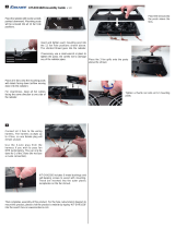
(4)
Remove fan shroud retaining clips. The shroud
has two
tabs
that fit into clips in the bottom of the
radiator.
Lift
the shroud up and position it back onto
the engine (Fig. 1).
(5)
Remove radiator top mounting brackets. The
brackets fit over support dowels on the radiator
inlet
tank (Fig. 1).
(6)
The bottom of the radiator has two dowels that
fit
into
holes in the lower support panel. Taking
care
not
to
damage
radiator cooling fins or tubes,
lift
ra-
Fig.
1
Radiator
and Fan
Shroud
diator
straight up out of engine compartment.
INSTALLATION
(1)
Position shroud rearward on engine.
(2)
Lower radiator into
position.
The dowels on the
bottom
of the radiator fit into alignment holes in the
lower
support panel.
(3)
Install
top mounting brackets. Tighten mount-
ing
screws to 23 N»m (17 in. lbs.) torque.
(4)
Connect radiator
hoses.
Install
hose
clamps.
(5)
Position fan shroud on radiator flange.
Install
retaining
clips.
(6)
Open
heater
valve.
(7) Fill
cooling system
with
coolant. Refer to
Fill-
ing
Cooling System in the 1991
Rear
Wheel
Drive
Truck
Service Manual.
(8)
Operate engine
until
it
reaches
normal temper-
ature. Check cooling system.
SPECIFICATIONS
COOLING
SYSTEM
CAPACITIES
RADIATOR
FAN
CAPACITY
IMINI
MOML
A
m
WIDTH
INCHES
IHKK-
NISS
ROWS
OF
TUBES
HNS
MR
INCH
DIAMETBR
INCHES
NO.
OP
BLADES
PITCH
INCH
CLWTCH
•NOAOIMINT
T1MMRATURI
QUARTS
units
Diesel
All
26
2.25 3
13 22.0
7
2.20
140°F
17.0
16.1
Diesel
All
•
26
2.25
3
13 22.0
7
2.20
140
°F
16.0 15.1
39107
881


•
INSTRUMENT
PANEL
AND
GAUGES
8E
-
1
INSTRUMENT PANEL AND GAUGES
OWERDRIWE
LOCKOUT
SWITCH
REMOVAL
(1)
Locate bracket
holding
chime module and inter-
mittent
wipe module (Fig.
2).
(2)
Remove
2
nuts
holding
bracket
to
instrument
panel support.
(3)
Remove ground
straps
and bracket.
(4)
Depress
lock
tabs
on
switch
and
push
it
out
of
the instrument panel.
INSTALLATION
(1) Hold wiring
connector
in
switch
opening.
(2)
Push
switch
on
to
wiring
connector.
(3)
Continue
to
push
until
switch
snaps
into
place.
(4)
Install
bracket
with
modules.
Be
sure
ground
straps
are
installed.
GROUND
COMBINATION
BUZZER
J918E-37
Fig.
1
Overdrive
Lockout
Switch Location
INTERMITTENT
WIPER
MODULE
BRACKET
INTERMITTENT
WIPER
CONTROL
MODULE
J918E-36
Fig.
2
Intermittent Wiper Module Bracket


•
SPEED
CONTROL
SYSTEM 8H -
1
SPEED CONTROL SYSTEM
CONTENTS
page
SERVICE
PROCEDURES
8
GENERAL
INFORMATION
The
speed
control
system
(Fig. 1) is electrically ac-
tuated and vacuum
operated.
The electronic control
is integrated into the
engine
controller, located next
to the battery. The controls are located on the
steer-
ing
wheel and
consist
of the ON/OFF, RESUME/AC-
CEL
and
SET/DECEL buttons.
The
system
is
designed
to
operate
at
speeds
between
35
mph (50
km/h)
and 85 mph (142 km/h).
WARNING;
THE USE
OF
SPEED
CONTROL
IS
NOT
RECOMMENDED
WHEN
DRIVING
CONDITIONS
DO
NOT
PERMIT
MAINTAINING
A
CONSTANT
SPEED,
SUCH
AS
IN
HEAVY
TRAFFIC
OR
ON
ROADS
THAT
ARE
WINDING,
ICY,
SNOW
COVERED,
OR
SLIP-
PERY.
TO
ACTIVATE:
By pushing the ON/OFF button
to the
depressed
latched position, ON, the
speed
con-
trol
function is now
ready
for use.
TO
DEACTIVATE:
A soft tap of the
brake
pedal,
or normal
brake
application while the
system
is
en-
gaged
will
disengage
speed
control without
erasing
memory. Pushing
the
ON/OFF button
to the un-
latched position or turning off the
ignition
erases
the
memory.
TO
SET SPEED: When the vehicle
has
reached
the desired
speed
push
the SET/DECEL button to en-
gage
system
which
will
then automatically maintain
the desired
speed.
TO
DECELERATE: When
speed
control
is en-
gaged,
holding the SET/DECEL button
depressed
al-
lows the vehicle to
coast
to
a
lower
speed
setting.
TO
RESUME:
After
disengaging the
speed
control
system
by
tapping
the
brake
pedal
push
the
RE-
SUME/ACCEL
button to return vehicle to the previ-
ously
set
speed.
TO
ACCELERATE: While
speed
control
is en-
gaged,
hold the RESUME/ACCEL button
depressed
and
release
at a
new desired
speed.
This
will
allow
page
TEST
PROCEDURES
4
the vehicle
to
continuously
accelerate
and
set at a
higher
speed
setting.
TAP-UP:
When
the
speed
control
system
is en-
gaged,
tapping the RESUME/ACCEL button
will
in-
crease
the
speed
setting
by 2
mph
(3
km/h).
The
system
will
respond
to multiple
tap-ups.
TO
ACCELERATE
for
PASSING:
Depress
the
accelerator
as
you would normally. When the pedal
is
released
the vehicle
will
return
to
the
speed
set-
ting
in memory.
SERVO
CONNECTOR
J918H-20
Fig,
1
Speed
Control
System

8H
- 2
SPEED
CONTROL
SYSTEM
WARNING: THE USE
Of
THE SPEED CONTROL
IS
NOT
RECOMMENDED WHEN DRIVING
CONDITIONS
DO NOT
PERMIT MAINTAINING
A CONSTANT SPEED, SUCH
AS
HEAVY
TRAFFIC
OR ON
ROADS THAT ARE WINDING,
ICY, SNOW COVERED
OR
SLIPPERY.
START
ENGINE
ACCELERATE
VEHICLE
TO
DESIRED
SPEED
SPEED
CONTROL
ENGAGES
WHEN
ENGINE
IS
STARTED
PUSH ON/OFF BUTTON
TO
"ON"
POSITION.
FAULTY
ELECTRICAL
CIRCUIT*
SPEED
CONTROL ENGAGES
WITHOUT PUSHING THE
"SET/DECEL"
BUTTON
PUSH AND RELEASE
"SET/DECEL"
BUTTON
FAULTY
ELECTRICAL
CIRCUIT*
j
:
DEFECTIVE
SERVO
DEFECTIVE
SERVO
REMOVE
FOOT
FROM
ACCELERATOR.
SPEED
SHOULD BE CONTROLLED
NO SPEED CONTROL WHEN
SET/DECEL
BUTTON
IS
PRESSED
AND
RELEASED
HUNTING SURGE
OR
SPEED
VARIATIONS
AT LOW SPEEDS
FUSE BLOWN
LOCK-UP
TORQUE
CONVERTER
ROUGHNESS
NO
VACUUM
AT
SERVO
AMPLIFICATION
OF
ENGINE
SURGE
SPEED
CONTROL
THROTTLE
CABLE
DISCONNECTED
DEFECTIVE
SERVO
IMPROPER
STOP LAMP
AND
SPEED
CONTROL
SWITCH
ADJUSTMENT
DEFECTIVE
CABLE
FAULTY
ELECTRICAL
CIRCUIT*
DEFECTIVE
ENGINE
CONTROLLER
EXCESSIVE
SAG
ON HILLS
OR
IN TRAILER TOWING
SPEED
SETTING AFTER
LOCK-IN,
TOO
HIGH
OR TOO LOW
ENGINE
PERFORAAANCE
VACUUM
LEAK
VACUUM
LEAK
DEFECTIVE
SERVO
EXCESSIVE
LOAD
MAY
REQUIRE
MANUAL
ASSISTANCE
ON
HILLS
DEFECTIVE
CABLE
DEFECTIVE
VACUUM
PUMP
DEFECTIVE
VACUUM
PUMP
REFER
TO
GROUP
5
-
BRAKES
FOR
VACUUM
PUMP
DIAGNOSIS.
DEFECTIVE
SERVO
*TESTS
AND
ADJUSTMENTS ARE DESCRIBED
IN APPROPRIATE SECTION
OF
SERVICE
MANUAL.
DEFECTIVE
VACUUM
PUMP
J918H-27X

SPEED
C01T10L SYSTEi SH
-
3
ZZZ3
DRIVE VEHICLE OVER
ROUGH ROAD
UNIT DISENGAGES
ON ROUGH ROAD
IMPROPER
ADJUSTMENT OF STOP
LAMP
AND SPEED
CONTROL
SWITCH*
FAULTY
ELECTRICAL
CIRCUIT
*
EfMGSNE
DOES
NOT
RETURN
TO
NORMAL IDLE
SPEED CONTROL
THROTTLE
CABLE
KINKED OR DAMAGED
STANDARD
THROTTLE
LINKAGE FAULTS
NO RESUME
WHEN
BUTTON IS PRESSED
TAP
BRAI
LIGHTLY
CONTROI
DISEN
<E
PEDAL
,
SPEED
.
SHOULD
GAGE
r
SPEED
CONTROL
DISENGAGES
PUSH
RESUME/ACCEL
SWITCH VEHICLE
SHOULD RESUME
PREVIOUSLY
MEMORIZED SPEED
VEHICLE
RESUMES
SPEED
DEPRESS BRAKE
PEDAL,
SPEED
CONTROL
SHOULD DISENGAGE
NO SYSTEM
DISENGAGEMENT
WHEN
BRAKE PEDAL
IS DEPRESSED
DEFECTIVE
OR
IMPROPERLY ADJUSTED
STOP
LAMP
AND
SPEED
CONTROL
SWITCH
SPEED
CONTROL
THROTTLE
CABLE
KINKED OR DAMAGED
FAULTY
ELECTRICAL
'
CIRCUIT*
DEFECTIVE
SERVO
SPEED
CONTROL
DISENGAGES
DEFECTIVE
SWITCH
FAULTY
ELECTRICAL
CIRCUIT'
NO SYSTEM
DISENGAGE
WHEN
BRAKE PEDAL IS
DEPRESSED
RESUME SPEED
IS POSSIBLE
BELOW
20
M.P.H.
DEFECTIVE
ENGINE
CONTROLLER
SPEED
CONTROL
SYSTEM OK
DEFECTIVE
DISTANCE
SENSOR
FAULTY
ELECTRICAL
CIRCUIT*
DEFECTIVE
ENGINE
CONTROLLER
J918H-28X
/