AUTOMATIC TRANSMISSION - 48RE
TABLE OF CONTENTS
page page
AUTOMATIC TRANSMISSION - 48RE
DESCRIPTION ........................132
OPERATION ..........................134
DIAGNOSIS AND TESTING
DIAGNOSIS AND TESTING - AUTOMATIC
TRANSMISSION .....................140
DIAGNOSIS AND TESTING - PRELIMINARY . 140
DIAGNOSIS AND TESTING - ROAD
TESTING ...........................140
DIAGNOSIS AND TESTING - HYDRAULIC
PRESSURE TEST ....................141
DIAGNOSIS AND TESTING - AIR TESTING
TRANSMISSION CLUTCH AND BAND
OPERATION ........................144
DIAGNOSIS AND TESTING - CONVERTER
HOUSING FLUID LEAK ................144
DIAGNOSIS AND TESTING - DIAGNOSIS
CHARTS ...........................145
STANDARD PROCEDURE - ALUMINUM
THREAD REPAIR .....................158
REMOVAL ............................158
DISASSEMBLY ........................160
CLEANING ...........................166
INSPECTION .........................166
ASSEMBLY ...........................166
INSTALLATION ........................174
SCHEMATICS AND DIAGRAMS
HYDRAULIC SCHEMATICS .............176
SPECIFICATIONS
TRANSMISSION .....................189
SPECIAL TOOLS
RE TRANSMISSION ..................191
ACCUMULATOR
DESCRIPTION ........................193
OPERATION ..........................193
INSPECTION .........................194
BANDS
DESCRIPTION ........................194
OPERATION ..........................194
ADJUSTMENTS
ADJUSTMENT - BANDS ...............195
BRAKE TRANSMISSION SHIFT INTERLOCK
SYSTEM
DESCRIPTION ........................196
OPERATION ..........................196
DIAGNOSIS AND TESTING - BRAKE
TRANSMISSION SHIFT INTERLOCK ......196
ADJUSTMENTS - BRAKE TRANSMISSION
SHIFT INTERLOCK ...................196
ELECTRONIC GOVERNOR
DESCRIPTION ........................197
OPERATION ..........................198
REMOVAL ............................199
INSTALLATION ........................200
EXTENSION HOUSING SEAL
REMOVAL ............................201
INSTALLATION ........................201
FLUID AND FILTER
DIAGNOSIS AND TESTING
DIAGNOSIS AND TESTING - EFFECTS OF
INCORRECT FLUID LEVEL .............201
DIAGNOSIS AND TESTING - CAUSES OF
BURNT FLUID .......................201
DIAGNOSIS AND TESTING - FLUID
CONTAMINATION ....................202
STANDARD PROCEDURE
STANDARD PROCEDURE - FLUID LEVEL
CHECK ............................202
STANDARD PROCEDURE - FLUID AND
FILTER REPLACEMENT ...............203
STANDARD PROCEDURE - TRANSMISSION
FILL ...............................204
FRONT CLUTCH
DESCRIPTION ........................205
OPERATION ..........................205
DISASSEMBLY ........................205
INSPECTION .........................206
ASSEMBLY ...........................207
FRONT SERVO
DESCRIPTION ........................208
OPERATION ..........................208
DISASSEMBLY ........................209
CLEANING ...........................209
INSPECTION .........................209
ASSEMBLY ...........................209
GEARSHIFT CABLE
DIAGNOSIS AND TESTING - GEARSHIFT
CABLE .............................210
REMOVAL ............................210
INSTALLATION ........................211
ADJUSTMENTS
GEARSHIFT CABLE ..................212
OIL PUMP
DESCRIPTION ........................213
OPERATION ..........................213
DISASSEMBLY ........................214
CLEANING ...........................214
INSPECTION .........................214
ASSEMBLY ...........................214
21 - 130 AUTOMATIC TRANSMISSION - 48RE DR

OUTPUT SHAFT FRONT BEARING
REMOVAL ............................216
INSTALLATION ........................216
OUTPUT SHAFT REAR BEARING
REMOVAL ............................216
INSTALLATION ........................217
OVERDRIVE CLUTCH
DESCRIPTION ........................217
OPERATION ..........................217
OVERDRIVE UNIT
REMOVAL ............................218
DISASSEMBLY ........................218
CLEANING ...........................225
INSPECTION .........................225
ASSEMBLY ...........................226
INSTALLATION ........................235
OVERRUNNING CLUTCH CAM/OVERDRIVE
PISTON RETAINER
DESCRIPTION ........................236
OPERATION ..........................236
DISASSEMBLY ........................236
CLEANING ...........................236
INSPECTION .........................237
ASSEMBLY ...........................237
PISTONS
DESCRIPTION ........................239
OPERATION ..........................239
PLANETARY GEARTRAIN/OUTPUT SHAFT
DESCRIPTION ........................241
OPERATION ..........................241
DISASSEMBLY ........................242
INSPECTION .........................243
ASSEMBLY ...........................244
REAR CLUTCH
DESCRIPTION ........................247
OPERATION ..........................248
DISASSEMBLY ........................248
CLEANING ...........................248
INSPECTION .........................248
ASSEMBLY ...........................249
REAR SERVO
DESCRIPTION ........................251
OPERATION ..........................251
DISASSEMBLY ........................251
CLEANING ...........................251
ASSEMBLY ...........................251
SHIFT MECHANISM
DESCRIPTION ........................252
OPERATION ..........................252
SOLENOID
DESCRIPTION ........................252
OPERATION ..........................252
SPEED SENSOR
DESCRIPTION ........................253
OPERATION ..........................253
THROTTLE VALVE CABLE
DESCRIPTION ........................253
ADJUSTMENTS - THROTTLE VALVE CABLE . 254
TORQUE CONVERTER
DESCRIPTION ........................255
OPERATION ..........................259
REMOVAL ............................260
INSTALLATION ........................260
TORQUE CONVERTER DRAINBACK VALVE
DESCRIPTION ........................261
OPERATION ..........................261
STANDARD PROCEDURE - TORQUE
CONVERTER DRAINBACK VALVE ........261
TOW/HAUL OVERDRIVE SWITCH
DESCRIPTION ........................261
OPERATION ..........................262
DIAGNOSIS AND TESTING - OVERDRIVE
ELECTRICAL CONTROLS ..............262
REMOVAL ............................262
INSTALLATION ........................262
TRANSMISSION RANGE SENSOR
DESCRIPTION ........................263
OPERATION ..........................263
DIAGNOSIS AND TESTING - TRANSMISSION
RANGE SENSOR (TRS) ................264
REMOVAL ............................265
INSTALLATION ........................266
TRANSMISSION TEMPERATURE SENSOR
DESCRIPTION ........................267
OPERATION ..........................267
VALVE BODY
DESCRIPTION ........................267
OPERATION ..........................272
REMOVAL ............................286
DISASSEMBLY ........................287
CLEANING ...........................298
INSPECTION .........................298
ASSEMBLY ...........................299
INSTALLATION ........................309
ADJUSTMENTS - VALVE BODY ...........310
DR AUTOMATIC TRANSMISSION - 48RE 21 - 131

AUTOMATIC TRANSMISSION -
48RE
DESCRIPTION
The 48RE (Fig. 1) is a four speed fully automatic
transmissions with an electronic governor. The 48RE
is equipped with a lock-up clutch in the torque con-
verter. First through third gear ranges are provided
by the clutches, bands, overrunning clutch, and plan-
etary gear sets in the transmission. Fourth gear
range is provided by the overdrive unit that contains
an overdrive clutch, direct clutch, planetary gear set,
and overrunning clutch.
The transmission contains a front, rear, and direct
clutch which function as the input driving compo-
nents. It also contains the kickdown (front) and the
low/reverse (rear) bands which, along with the over-
running clutch and overdrive clutch, serve as the
holding components. The driving and holding compo-
nents combine to select the necessary planetary gear
components, in the front, rear, or overdrive planetary
gear set, transfer the engine power from the input
shaft through to the output shaft.
The valve body is mounted to the lower side of the
transmission and contains the valves to control pres-
sure regulation, fluid flow control, and clutch/band
application. The oil pump is mounted at the front of
the transmission and is driven by the torque con-
verter hub. The pump supplies the oil pressure nec-
essary for clutch/band actuation and transmission
lubrication.
21 - 132 AUTOMATIC TRANSMISSION - 48RE DR

Fig. 1 48RE Transmission
DR AUTOMATIC TRANSMISSION - 48RE 21 - 133
AUTOMATIC TRANSMISSION - 48RE (Continued)

IDENTIFICATION
Transmission identification numbers are stamped
on the left side of the case just above the oil pan gas-
ket surface (Fig. 2). Refer to this information when
ordering replacement parts.
GEAR RATIOS
The 48RE gear ratios are:
1st .................................2.45:1
2nd ................................1.45:1
3rd ................................1.00:1
4th .................................0.69:1
Rev. ................................2.20:1
OPERATION
The application of each driving or holding compo-
nent is controlled by the valve body based upon the
manual lever position, throttle pressure, and gover-
nor pressure. The governor pressure is a variable
pressure input to the valve body and is one of the
signals that a shift is necessary. First through fourth
gear are obtained by selectively applying and releas-
ing the different clutches and bands. Engine power is
thereby routed to the various planetary gear assem-
blies which combine with the overrunning clutch
assemblies to generate the different gear ratios. The
torque converter clutch is hydraulically applied and
is released when fluid is vented from the hydraulic
circuit by the torque converter control (TCC) solenoid
on the valve body. The torque converter clutch is con-
trolled by the Powertrain Control Module (PCM). The
torque converter clutch engages in fourth gear, and
in third gear under various conditions, such as when
the O/D switch is OFF, when the vehicle is cruising
on a level surface after the vehicle has warmed up.
The torque converter clutch can also be engaged in
the MANUAL SECOND gear position if high trans-
mission temperatures are sensed by the PCM. The
torque converter clutch will disengage momentarily
when an increase in engine load is sensed by the
PCM, such as when the vehicle begins to go uphill or
the throttle pressure is increased. The torque con-
verter clutch feature increases fuel economy and
reduces the transmission fluid temperature.
Since the overdrive clutch is applied in fourth gear
only and the direct clutch is applied in all ranges
except fourth gear, the transmission operation for
park, neutral, and first through third gear will be
described first. Once these powerflows are described,
the third to fourth shift sequence will be described.
1 - TORQUE CONVERTER 10 - OVERDRIVE CLUTCH
2 - INPUT SHAFT 11 - DIRECT CLUTCH
3 - OIL PUMP 12 - PLANETARY GEAR
4 - FRONT BAND 13 - INTERMEDIATE SHAFT
5 - FRONT CLUTCH 14 - OVERDRIVE OVERRUNNING CLUTCH
6 - REAR CLUTCH 15 - DIRECT CLUTCH SPRING
7 - PLANETARIES 16 - OVERDRIVE PISTON RETAINER
8 - REAR BAND 17 - OIL PAN
9 - OVERRUNNING CLUTCH 18 - VALVE BODY
Fig. 2 Transmission Part Number And Serial
Number Location
1 - PART NUMBER
2 - BUILD DATE
3 - SERIAL NUMBER
21 - 134 AUTOMATIC TRANSMISSION - 48RE DR
AUTOMATIC TRANSMISSION - 48RE (Continued)

PARK POWERFLOW
As the engine is running and the crankshaft is
rotating, the flexplate and torque converter, which
are also bolted to it, are all rotating in a clockwise
direction as viewed from the front of the engine. The
notched hub of the torque converter is connected to
the oil pump’s internal gear, supplying the transmis-
sion with oil pressure. As the converter turns, it
turns the input shaft in a clockwise direction. As the
input shaft is rotating, the front clutch hub-rear
clutch retainer and all their associated parts are also
rotating, all being directly connected to the input
shaft. The power flow from the engine through the
front clutch hub and rear clutch retainer stops at the
rear clutch retainer. Therefore, no power flow to the
output shaft occurs because no clutches are applied.
The only mechanism in use at this time is the park-
ing sprag (Fig. 3), which locks the parking gear on
the output shaft to the transmission case.
NEUTRAL POWERFLOW
With the gear selector in the NEUTRAL position
(Fig. 4), the power flow of the transmission is essen-
tially the same as in the park position. The only
operational difference is that the parking sprag has
been disengaged, unlocking the output shaft from the
transmission case and allowing it to move freely.
Fig. 3 Park Powerflow
1 - PAWL ENGAGED FOR PARK
2 - PARK SPRAG
3 - OUTPUT SHAFT
Fig. 4 Neutral Powerflow
1 - PAWL DISENGAGED FOR NEUTRAL
2 - PARK SPRAG
3 - OUTPUT SHAFT
4 - CAM
5-PAWL
DR AUTOMATIC TRANSMISSION - 48RE 21 - 135
AUTOMATIC TRANSMISSION - 48RE (Continued)

REVERSE POWERFLOW
When the gear selector is moved into the
REVERSE position (Fig. 5), the front clutch and the
rear band are applied. With the application of the
front clutch, engine torque is applied to the sun gear,
turning it in a clockwise direction. The clockwise
rotation of the sun gear causes the rear planet pin-
ions to rotate against engine rotation in a counter-
clockwise direction. The rear band is holding the low
reverse drum, which is splined to the rear carrier.
Since the rear carrier is being held, the torque from
the planet pinions is transferred to the rear annulus
gear, which is splined to the output shaft. The output
shaft in turn rotates with the annulus gear in a
counterclockwise direction giving a reverse gear out-
put. The entire transmission of torque is applied to
the rear planetary gearset only. Although there is
torque input to the front gearset through the sun
gear, no other member of the gearset is being held.
During the entire reverse stage of operation, the
front planetary gears are in an idling condition.
Fig. 5 Reverse Powerflow
1 - FRONT CLUTCH ENGAGED 5 - OUTPUT SHAFT
2 - OUTPUT SHAFT 6 - INPUT SHAFT
3 - LOW/REVERSE BAND APPLIED 7 - FRONT CLUTCH ENGAGED
4 - INPUT SHAFT 8 - LOW/REVERSE BAND APPLIED
21 - 136 AUTOMATIC TRANSMISSION - 48RE DR
AUTOMATIC TRANSMISSION - 48RE (Continued)

FIRST GEAR POWERFLOW
When the gearshift lever is moved into the DRIVE
position the transmission goes into first gear (Fig. 6).
As soon as the transmission is shifted from PARK or
NEUTRAL to DRIVE, the rear clutch applies, apply-
ing the rear clutch pack to the front annulus gear.
Engine torque is now applied to the front annulus
gear turning it in a clockwise direction. With the
front annulus gear turning in a clockwise direction, it
causes the front planets to turn in a clockwise direc-
tion. The rotation of the front planets cause the sun
to revolve in a counterclockwise direction. The sun
gear now transfers its counterclockwise rotation to
the rear planets which rotate back in a clockwise
direction. With the rear annulus gear stationary, the
rear planet rotation on the annulus gear causes the
rear planet carrier to revolve in a counterclockwise
direction. The rear planet carrier is splined into the
low-reverse drum, and the low reverse drum is
splined to the inner race of the over-running clutch.
With the over-running clutch locked, the planet car-
rier is held, and the resulting torque provided by the
planet pinions is transferred to the rear annulus
gear. The rear annulus gear is splined to the output
shaft and rotated along with it (clockwise) in an
underdrive gear reduction mode.
Fig. 6 First Gear Powerflow
1 - OUTPUT SHAFT 5 - OVER-RUNNING CLUTCH HOLDING
2 - OVER-RUNNING CLUTCH HOLDING 6 - INPUT SHAFT
3 - REAR CLUTCH APPLIED 7 - REAR CLUTCH APPLIED
4 - OUTPUT SHAFT 8 - INPUT SHAFT
DR AUTOMATIC TRANSMISSION - 48RE 21 - 137
AUTOMATIC TRANSMISSION - 48RE (Continued)

SECOND GEAR POWERFLOW
In DRIVE-SECOND (Fig. 7), the same elements
are applied as in MANUAL-SECOND. Therefore, the
power flow will be the same, and both gears will be
discussed as one in the same. In DRIVE-SECOND,
the transmission has proceeded from first gear to its
shift point, and is shifting from first gear to second.
The second gear shift is obtained by keeping the rear
clutch applied and applying the front (kickdown)
band. The front band holds the front clutch retainer
that is locked to the sun gear driving shell. With the
rear clutch still applied, the input is still on the front
annulus gear turning it clockwise at engine speed.
Now that the front band is holding the sun gear sta-
tionary, the annulus rotation causes the front planets
to rotate in a clockwise direction. The front carrier is
then also made to rotate in a clockwise direction but
at a reduced speed. This will transmit the torque to
the output shaft, which is directly connected to the
front planet carrier. The rear planetary annulus gear
will also be turning because it is directly splined to
the output shaft. All power flow has occurred in the
front planetary gear set during the drive-second
stage of operation, and now the over-running clutch,
in the rear of the transmission, is disengaged and
freewheeling on its hub.
Fig. 7 Second Gear Powerflow
1 - KICKDOWN BAND APPLIED 6 - INPUT SHAFT
2 - OUTPUT SHAFT 7 - REAR CLUTCH APPLIED
3 - REAR CLUTCH ENGAGED 8 - KICKDOWN BAND APPLIED
4 - OUTPUT SHAFT 9 - INPUT SHAFT
5 - OVER-RUNNING CLUTCH FREE-WHEELING
21 - 138 AUTOMATIC TRANSMISSION - 48RE DR
AUTOMATIC TRANSMISSION - 48RE (Continued)

DIRECT DRIVE POWERFLOW
The vehicle has accelerated and reached the shift
point for the 2-3 upshift into direct drive (Fig. 8).
When the shift takes place, the front band is
released, and the front clutch is applied. The rear
clutch stays applied as it has been in all the forward
gears. With the front clutch now applied, engine
torque is now on the front clutch retainer, which is
locked to the sun gear driving shell. This means that
the sun gear is now turning in engine rotation (clock-
wise) and at engine speed. The rear clutch is still
applied so engine torque is also still on the front
annulus gear. If two members of the same planetary
set are driven, direct drive results. Therefore, when
two members are rotating at the same speed and in
the same direction, it is the same as being locked up.
The rear planetary set is also locked up, given the
sun gear is still the input, and the rear annulus gear
must turn with the output shaft. Both gears are
turning in the same direction and at the same speed.
The front and rear planet pinions do not turn at all
in direct drive. The only rotation is the input from
the engine to the connected parts, which are acting
as one common unit, to the output shaft.
FOURTH GEAR POWERFLOW
Fourth gear overdrive range is electronically con-
trolled and hydraulically activated. Various sensor
inputs are supplied to the powertrain control module
to operate the overdrive solenoid on the valve body.
The solenoid contains a check ball that opens and
closes a vent port in the 3-4 shift valve feed passage.
The overdrive solenoid (and check ball) are not ener-
gized in first, second, third, or reverse gear. The vent
port remains open, diverting line pressure from the
2-3 shift valve away from the 3-4 shift valve. The
Tow/Haul control switch must be in the ON position
to transmit overdrive status to the PCM. A 3-4
upshift occurs only when the overdrive solenoid is
energized by the PCM. The PCM energizes the over-
drive solenoid during the 3-4 upshift. This causes the
solenoid check ball to close the vent port allowing
line pressure from the 2-3 shift valve to act directly
on the 3-4 upshift valve. Line pressure on the 3-4
shift valve overcomes valve spring pressure moving
the valve to the upshift position. This action exposes
the feed passages to the 3-4 timing valve, 3-4 quick
fill valve, 3-4 accumulator, and ultimately to the
overdrive piston. Line pressure through the timing
Fig. 8 Direct Drive Powerflow
1 - FRONT CLUTCH APPLIED 6 - INPUT SHAFT
2 - OVER-RUNNING CLUTCH FREE-WHEELING 7 - OVER-RUNNING CLUTCH FREE-WHEELING
3 - OUTPUT SHAFT 8 - REAR CLUTCH APPLIED
4 - REAR CLUTCH APPLIED 9 - FRONT CLUTCH APPLIED
5 - OUTPUT SHAFT 10 - INPUT SHAFT
DR AUTOMATIC TRANSMISSION - 48RE 21 - 139
AUTOMATIC TRANSMISSION - 48RE (Continued)

valve moves the overdrive piston into contact with
the overdrive clutch. The direct clutch is disengaged
before the overdrive clutch is engaged. The boost
valve provides increased fluid apply pressure to the
overdrive clutch during 3-4 upshifts, and when accel-
erating in fourth gear. The 3-4 accumulator cushions
overdrive clutch engagement to smooth 3-4 upshifts.
The accumulator is charged at the same time as
apply pressure acts against the overdrive piston.
DIAGNOSIS AND TESTING
DIAGNOSIS AND TESTING - AUTOMATIC
TRANSMISSION
Automatic transmission problems can be a result of
poor engine performance, incorrect fluid level, incor-
rect linkage or cable adjustment, band or hydraulic
control pressure adjustments, hydraulic system mal-
functions or electrical/mechanical component mal-
functions. Begin diagnosis by checking the easily
accessible items such as: fluid level and condition,
linkage adjustments and electrical connections. A
road test will determine if further diagnosis is neces-
sary.
DIAGNOSIS AND TESTING - PRELIMINARY
Two basic procedures are required. One procedure
for vehicles that are drivable and an alternate proce-
dure for disabled vehicles (will not back up or move
forward).
VEHICLE IS DRIVEABLE
(1) Check for transmission fault codes using DRBt
scan tool.
(2) Check fluid level and condition.
(3) Adjust throttle and gearshift linkage if com-
plaint was based on delayed, erratic, or harsh shifts.
(4) Road test and note how transmission upshifts,
downshifts, and engages.
(5) Perform hydraulic pressure test if shift prob-
lems were noted during road test.
(6) Perform air-pressure test to check clutch-band
operation.
VEHICLE IS DISABLED
(1) Check fluid level and condition.
(2) Check for broken or disconnected gearshift or
throttle linkage.
(3) Check for cracked, leaking cooler lines, or loose
or missing pressure-port plugs.
(4) Raise and support vehicle on safety stands,
start engine, shift transmission into gear, and note
following:
(a) If propeller shaft turns but wheels do not,
problem is with differential or axle shafts.
(b) If propeller shaft does not turn and transmis-
sion is noisy, stop engine. Remove oil pan, and
check for debris. If pan is clear, remove transmis-
sion and check for damaged drive plate, converter,
oil pump, or input shaft.
(c) If propeller shaft does not turn and transmis-
sion is not noisy, perform hydraulic-pressure test to
determine if problem is hydraulic or mechanical.
DIAGNOSIS AND TESTING - ROAD TESTING
Before road testing, be sure the fluid level and con-
trol cable adjustments have been checked and
adjusted if necessary. Verify that diagnostic trouble
codes have been resolved.
Observe engine performance during the road test.
A poorly tuned engine will not allow accurate analy-
sis of transmission operation.
Operate the transmission in all gear ranges. Check
for shift variations and engine flare which indicates
slippage. Note if shifts are harsh, spongy, delayed,
early, or if part throttle downshifts are sensitive.
Slippage indicated by engine flare, usually means
clutch, band or overrunning clutch problems. If the
condition is advanced, an overhaul will be necessary
to restore normal operation.
A slipping clutch or band can often be determined
by comparing which internal units are applied in the
various gear ranges. The Clutch and Band Applica-
tion chart provides a basis for analyzing road test
results.
21 - 140 AUTOMATIC TRANSMISSION - 48RE DR
AUTOMATIC TRANSMISSION - 48RE (Continued)

CLUTCH AND BAND APPLICATION CHART
SHIFT
LEVER
POSITION
TRANSMISSION CLUTCHES AND BANDS OVERDRIVE CLUTCHES
FRONT
CLUTCH
FRONT
BAND
REAR
CLUTCH
REAR
BAND
OVER-
RUNNING
CLUTCH
OVER-
DRIVE
CLUTCH
DIRECT
CLUTCH
OVER-
RUNNING
CLUTCH
Reverse X X X
Drive -
First
XXXX
Drive -
Second
XX XX
Drive -
Third
XX XX
Drive -
Fourth
XX X
Manual
Second
XX XX
Manual
First
XXX XX
Note that the rear clutch is applied in all forward
ranges (D, 2, 1). The transmission overrunning clutch
is applied in first gear (D, 2 and 1 ranges) only. The
rear band is applied in 1 and R range only.
Note that the overdrive clutch is applied only in
fourth gear and the overdrive direct clutch and over-
running clutch are applied in all ranges except fourth
gear.
For example: If slippage occurs in first gear in D
and 2 range but not in 1 range, the transmission
overrunning clutch is faulty. Similarly, if slippage
occurs in any two forward gears, the rear clutch is
slipping.
Applying the same method of analysis, note that
the front and rear clutches are applied simulta-
neously only in D range third and fourth gear. If the
transmission slips in third gear, either the front
clutch or the rear clutch is slipping.
If the transmission slips in fourth gear but not in
third gear, the overdrive clutch is slipping. By select-
ing another gear which does not use these clutches,
the slipping unit can be determined. For example, if
the transmission also slips in Reverse, the front
clutch is slipping. If the transmission does not slip in
Reverse, the rear clutch is slipping.
If slippage occurs during the 3-4 shift or only in
fourth gear, the overdrive clutch is slipping. Simi-
larly, if the direct clutch were to fail, the transmis-
sion would lose both reverse gear and overrun
braking in 2 position (manual second gear).
If the transmission will not shift to fourth gear, the
control switch, overdrive solenoid or related wiring
may also be the problem cause.
This process of elimination can be used to identify
a slipping unit and check operation. Proper use of
the Clutch and Band Application Chart is the key.
Although road test analysis will help determine the
slipping unit, the actual cause of a malfunction usu-
ally cannot be determined until hydraulic and air
pressure tests are performed. Practically any condi-
tion can be caused by leaking hydraulic circuits or
sticking valves.
Unless a malfunction is obvious, such as no drive
in D range first gear, do not disassemble the trans-
mission. Perform the hydraulic and air pressure tests
to help determine the probable cause.
DIAGNOSIS AND TESTING - HYDRAULIC
PRESSURE TEST
Hydraulic test pressures range from a low of one
psi (6.895 kPa) governor pressure, to 300 psi (2068
kPa) at the rear servo pressure port in reverse.
An accurate tachometer and pressure test gauges
are required. Test Gauge C-3292 has a 100 psi range
and is used at the accumulator, governor, and front
servo ports. Test Gauge C-3293-SP has a 300 psi
range and is used at the rear servo and overdrive
ports where pressures exceed 100 psi.
Pressure Test Port Locations
Test ports are located at both sides of the transmis-
sion case (Fig. 9).
Line pressure is checked at the accumulator port
on the right side of the case. The front servo pressure
port is at the right side of the case just behind the
filler tube opening.
DR AUTOMATIC TRANSMISSION - 48RE 21 - 141
AUTOMATIC TRANSMISSION - 48RE (Continued)

The rear servo and governor pressure ports are at
the right rear of the transmission case. The overdrive
clutch pressure port is at the left rear of the case.
Test One - Transmission In Manual Low
This test checks pump output, pressure regulation,
and condition of the rear clutch and servo circuit.
Both test gauges are required for this test.
(1) Connect tachometer to engine. Position tachom-
eter so it can be observed from driver seat if helper
will be operating engine. Raise vehicle on hoist that
will allow rear wheels to rotate freely.
(2) Connect 100 psi Gauge C-3292 to accumulator
port. Then connect 300 psi Gauge C-3293-SP to rear
servo port.
(3) Disconnect throttle and gearshift cables from
levers on transmission valve body manual shaft.
(4) Have helper start and run engine at 1000 rpm.
(5) Move transmission shift lever fully forward
into 1 range.
(6) Gradually move transmission throttle lever
from full forward to full rearward position and note
pressures on both gauges:
• Line pressure at accumulator port should be
54-60 psi (372-414 kPa) with throttle lever forward
and gradually increase to 90-96 psi (621-662 kPa) as
throttle lever is moved rearward.
• Rear servo pressure should be same as line pres-
sure within 3 psi (20.68 kPa).
Test Two - Transmission In 2 Range
This test checks pump output, line pressure and
pressure regulation. Use 100 psi Test Gauge C-3292
for this test.
(1) Leave vehicle in place on hoist and leave Test
Gauge C-3292 connected to accumulator port.
(2) Have helper start and run engine at 1000 rpm.
(3) Move transmission shift lever one detent rear-
ward from full forward position. This is 2 range.
(4) Move transmission throttle lever from full for-
ward to full rearward position and read pressure on
gauge.
(5) Line pressure should be 54-60 psi (372-414
kPa) with throttle lever forward and gradually
increase to 90-96 psi (621-662 kPa) as lever is moved
rearward.
Test Three - Transmission In D Range Third Gear
This test checks pressure regulation and condition
of the clutch circuits. Both test gauges are required
for this test.
(1) Turn OD switch off.
(2) Leave vehicle on hoist and leave Gauge C-3292
in place at accumulator port.
(3) Move Gauge C-3293-SP over to front servo port
for this test.
(4) Have helper start and run engine at 1600 rpm
for this test.
(5) Move transmission shift lever two detents rear-
ward from full forward position. This is D range.
(6) Read pressures on both gauges as transmission
throttle lever is gradually moved from full forward to
full rearward position:
• Line pressure at accumulator in D range third
gear, should be 54-60 psi (372-414 kPa) with throttle
lever forward and increase as lever is moved rear-
ward.
• Front servo pressure in D range third gear,
should be within 3 psi (21 kPa) of line pressure up to
kickdown point.
Test Four - Transmission In Reverse
This test checks pump output, pressure regulation
and the front clutch and rear servo circuits. Use 300
psi Test Gauge C-3293-SP for this test.
(1) Leave vehicle on hoist and leave gauge C-3292
in place at accumulator port.
(2) Move 300 psi Gauge C-3293-SP back to rear
servo port.
Fig. 9 Pressure Test Port Locations
1 - REAR SERVO TEST PORT
2 - GOVERNOR TEST PORT
3 - ACCUMULATOR TEST PORT
4 - FRONT SERVO TEST PORT
5 - OVERDRIVE CLUTCH TEST PORT
21 - 142 AUTOMATIC TRANSMISSION - 48RE DR
AUTOMATIC TRANSMISSION - 48RE (Continued)

(3) Have helper start and run engine at 1600 rpm
for test.
(4)
Move transmission shift lever four detents rear-
ward from full forward position. This is Reverse range.
(5) Move transmission throttle lever fully forward
then fully rearward and note reading at Gauge
C-3293-SP.
(6) Pressure should be 145 - 175 psi (1000-1207
kPa) with throttle lever forward and increase to 230 -
280 psi (1586-1931 kPa) as lever is gradually moved
rearward.
Test Five - Governor Pressure
This test checks governor operation by measuring
governor pressure response to changes in vehicle
speed. It is usually not necessary to check governor
operation unless shift speeds are incorrect or if the
transmission will not downshift. The test should be
performed on the road or on a hoist that will allow
the rear wheels to rotate freely.
(1) Move 100 psi Test Gauge C-3292 to governor
pressure port.
(2) Move transmission shift lever two detents rear-
ward from full forward position. This is D range.
(3) Have helper start and run engine at curb idle
speed. Then firmly apply service brakes so wheels
will not rotate.
(4) Note governor pressure:
•
Governor pressure should be no more than 20.6
kPa (3 psi) at curb idle speed and wheels not rotating.
• If pressure exceeds 20.6 kPa (3 psi), a fault
exists in governor pressure control system.
(5) Release brakes, slowly increase engine speed,
and observe speedometer and pressure test gauge (do
not exceed 30 mph on speedometer). Governor pres-
sure should increase in proportion to vehicle speed.
Or approximately 6.89 kPa (1 psi) for every 1 mph.
(6) Governor pressure rise should be smooth and
drop back to no more than 20.6 kPa (3 psi), after
engine returns to curb idle and brakes are applied to
prevent wheels from rotating.
(7)
Compare results of pressure test with analysis
chart.
Test Six - Transmission In Overdrive Fourth Gear
This test checks line pressure at the overdrive
clutch in fourth gear range. Use 300 psi Test Gauge
C-3293-SP for this test. The test should be performed
on the road or on a chassis dyno.
(1)
Remove tachometer; it is not needed for this test.
(2) Move 300 psi Gauge to overdrive clutch pres-
sure test port. Then remove other gauge and reinstall
test port plug.
(3) Lower vehicle.
(4) Turn OD switch on.
(5) Secure test gauge so it can be viewed from
drivers seat.
(6) Start engine and shift into D range.
(7) Increase vehicle speed gradually until 3-4 shift
occurs and note gauge pressure.
(8) Pressure should be 524-565 kPa (76-82 psi)
with closed throttle and increase to 690-896 kPa
(100-130 psi) at 1/2 to 3/4 throttle. Note that pres-
sure can increase to around 965 kPa (140 psi) at full
throttle.
(9) Return to shop or move vehicle off chassis
dyno.
PRESSURE TEST ANALYSIS CHART
TEST CONDITION INDICATION
Line pressure OK during
any one test
Pump and regulator
valve OK
Line pressure OK in R
but low in D, 2, 1
Leakage in rear clutch
area (seal rings, clutch
seals)
Pressure low in D Fourth
Gear Range
Overdrive clutch piston
seal, or check ball
problem
Pressure OK in 1, 2 but
low in D3 and R
Leakage in front clutch
area
Pressure OK in 2 but low
in R and 1
Leakage in rear servo
Front servo pressure in 2 Leakage in servo; broken
servo ring or cracked
servo piston
Pressure low in all
positions
Clogged filter, stuck
regulator valve, worn or
faulty pump, low oil level
Governor pressure too
high at idle speed
Governor pressure
solenoid valve system
fault. Refer to diagnostic
book.
Governor pressure low at
all mph figures
Faulty governor pressure
solenoid, transmission
control module, or
governor pressure
sensor
Lubrication pressure low
at all throttle positions
Clogged fluid cooler or
lines, seal rings leaking,
worn pump bushings,
pump, clutch retainer, or
clogged filter.
Line pressure high Output shaft plugged,
sticky regulator valve
Line pressure low Sticky regulator valve,
clogged filter, worn pump
DR AUTOMATIC TRANSMISSION - 48RE 21 - 143
AUTOMATIC TRANSMISSION - 48RE (Continued)

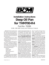
DIAGNOSIS AND TESTING - AIR TESTING
TRANSMISSION CLUTCH AND BAND
OPERATION
Air-pressure testing can be used to check transmis-
sion front/rear clutch and band operation. The test
can be conducted with the transmission either in the
vehicle or on the work bench, as a final check, after
overhaul.
Air-pressure testing requires that the oil pan and
valve body be removed from the transmission. The
servo and clutch apply passages are shown (Fig. 10).
Front Clutch Air Test
Place one or two fingers on the clutch housing and
apply air pressure through front clutch apply pas-
sage. Piston movement can be felt and a soft thump
heard as the clutch applies.
Rear Clutch Air Test
Place one or two fingers on the clutch housing and
apply air pressure through rear clutch apply passage.
Piston movement can be felt and a soft thump heard
as the clutch applies.
Front Servo Air Test
Apply air pressure to the front servo apply pas-
sage. The servo rod should extend and cause the
band to tighten around the drum. Spring pressure
should release the servo when air pressure is
removed.
Rear Servo Air Test
Apply air pressure to the rear servo apply passage.
The servo rod should extend and cause the band to
tighten around the drum. Spring pressure should
release the servo when air pressure is removed.
DIAGNOSIS AND TESTING - CONVERTER
HOUSING FLUID LEAK
When diagnosing converter housing fluid leaks,
two items must be established before repair.
(1) Verify that a leak condition actually exists.
(2) Determined the true source of the leak.
Some suspected converter housing fluid leaks may
not be leaks at all. They may only be the result of
residual fluid in the converter housing, or excess
fluid spilled during factory fill or fill after repair.
Converter housing leaks have several potential
sources. Through careful observation, a leak source
can be identified before removing the transmission
for repair. Pump seal leaks tend to move along the
drive hub and onto the rear of the converter. Pump
body leaks follow the same path as a seal leak (Fig.
11). Pump vent or pump attaching bolt leaks are gen-
erally deposited on the inside of the converter hous-
ing and not on the converter itself (Fig. 11). Pump
o-ring or gasket leaks usually travel down the inside
of the converter housing. Front band lever pin plug
leaks are generally deposited on the housing and not
on the converter.
Fig. 10 Air Pressure Test Passages
1 - LINE PRESSURE TO ACCUMULATOR
2 - REAR SERVO APPLY
3 - FRONT SERVO APPLY
4 - FRONT SERVO RELEASE
5 - PUMP SUCTION
6 - PUMP PRESSURE
7 - FRONT CLUTCH APPLY
8 - REAR CLUTCH APPLY
9 - TO TORQUE CONVERTOR
10 - TO COOLER
11 - FROM TORQUE CONVERTER
21 - 144 AUTOMATIC TRANSMISSION - 48RE DR
AUTOMATIC TRANSMISSION - 48RE (Continued)

TORQUE CONVERTER LEAK POINTS
Possible sources of converter leaks are:
• Leaks at the weld joint around the outside diam-
eter weld.
• Leaks at the converter hub weld.
CONVERTER HOUSING AREA LEAK CORRECTION
(1) Remove converter.
(2) Tighten front band adjusting screw until band
is tight around front clutch retainer. This prevents
front/rear clutches from coming out when oil pump is
removed.
(3) Remove oil pump and remove pump seal.
Inspect pump housing drainback and vent holes for
obstructions. Clear holes with solvent and wire.
(4) Inspect pump bushing and converter hub. If
bushing is scored, replace it. If converter hub is
scored, either polish it with crocus cloth or replace
converter.
(5) Install new pump seal, O-ring, and gasket.
Replace oil pump if cracked, porous or damaged in
any way. Be sure to loosen the front band before
installing the oil pump, damage to the oil pump seal
may occur if the band is still tightened to the front
clutch retainer.
(6) Loosen kickdown lever pin access plug three
turns. Apply Loctite™ 592, or Permatext No.2to
plug threads and tighten plug to 17 N·m (150 in. lbs.)
torque.
(7) Adjust front band.
(8) Lubricate pump seal and converter hub with
transmission fluid or petroleum jelly and install con-
verter.
(9) Install transmission and converter housing
dust shield.
(10) Lower vehicle.
DIAGNOSIS AND TESTING - DIAGNOSIS
CHARTS
The diagnosis charts provide additional reference
when diagnosing a transmission fault. The charts
provide general information on a variety of transmis-
sion, overdrive unit and converter clutch fault condi-
tions.
The hydraulic flow charts in the Schematics and
Diagrams section of this group, outline fluid flow and
hydraulic circuitry. Circuit operation is provided for
PARK, NEUTRAL, FIRST, SECOND, THIRD,
FOURTH, MANUAL FIRST, MANUAL SECOND,
and REVERSE gear ranges. Normal working pres-
sures are also supplied for each of the gear ranges.
Fig. 11 Converter Housing Leak Paths
1 - PUMP SEAL
2 - PUMP VENT
3 - PUMP BOLT
4 - PUMP GASKET
5 - CONVERTER HOUSING
6 - CONVERTER
7 - REAR MAIN SEAL LEAK
DR AUTOMATIC TRANSMISSION - 48RE 21 - 145
AUTOMATIC TRANSMISSION - 48RE (Continued)

DIAGNOSIS CHARTS
CONDITION POSSIBLE CAUSES CORRECTION
HARSH ENGAGEMENT
(FROM NEUTRAL TO
DRIVE OR REVERSE)
1. Fluid Level Low. 1. Add Fluid
2. Throttle Linkage Mis-adjusted. 2. Adjust linkage - setting may be too long.
3. Mount and Driveline Bolts Loose. 3. Check engine mount, transmission
mount, propeller shaft, rear spring to body
bolts, rear control arms, crossmember and
axle bolt torque. Tighten loose bolts and
replace missing bolts.
4. U-Joint Worn/Broken. 4. Remove propeller shaft and replace
U-Joint.
5. Axle Backlash Incorrect. 5. Check per Service Manual. Correct as
needed.
6. Hydraulic Pressure Incorrect. 6. Check pressure. Remove, overhaul or
adjust valve body as needed.
7. Band Mis-adjusted. 7. Adjust rear band.
8. Valve Body Check Balls Missing. 8. Inspect valve body for proper check ball
installation.
9. Axle Pinion Flange Loose. 9. Replace nut and check pinion threads
before installing new nut. Replace pinion
gear if threads are damaged.
10. Clutch, band or planetary
component damaged.
10. Remove, disassemble and repair
transmission as necessary.
11. Converter Clutch Faulty. 11. Replace converter and flush cooler and
line before installing new converter.
21 - 146 AUTOMATIC TRANSMISSION - 48RE DR
AUTOMATIC TRANSMISSION - 48RE (Continued)

CONDITION POSSIBLE CAUSES CORRECTION
DELAYED ENGAGEMENT
(FROM NEUTRAL TO
DRIVE OR REVERSE)
1. Fluid Level Low. 1. Correct level and check for leaks.
2. Filter Clogged. 2. Change filter.
3. Gearshift Linkage Mis-adjusted. 3. Adjust linkage and repair linkage if worn
or damaged.
4. Torque Converter Drain Back (Oil
drains from torque converter into
transmission sump).
4. If vehicle moves normally after 5
seconds after shifting into gear, no repair is
necessary. If longer, inspect pump bushing
for wear. Replace pump house.
5. Rear Band Mis-adjusted. 5. Adjust band.
6. Valve Body Filter Plugged. 6. Replace fluid and filter. If oil pan and old
fluid were full of clutch disc material and/or
metal particles, overhaul will be necessary.
7. Oil Pump Gears Worn/Damaged. 7. Remove transmission and replace oil
pump.
8. Governor Circuit and Solenoid
Valve Electrical Fault.
8. Test with DRBT scan tool and repair as
required.
9. Hydraulic Pressure Incorrect. 9. Perform pressure test, remove
transmission and repair as needed.
10. Reaction Shaft Seal Rings
Worn/Broken.
10. Remove transmission, remove oil pump
and replace seal rings.
11. Rear Clutch/Input Shaft, Rear
Clutch Seal Rings Damaged.
11. Remove and disassemble transmission
and repair as necessary.
12. Regulator Valve Stuck. 12. Clean.
13. Cooler Plugged. 13. Transfer case failure can plug cooler.
NO DRIVE RANGE
(REVERSE OK)
1. Fluid Level Low. 1. Add fluid and check for leaks if drive is
restored.
2. Gearshift Linkage/Cable
Loose/Misadjusted.
2. Repair or replace linkage components.
3. Rear Clutch Burnt. 3. Remove and disassemble transmission
and rear clutch and seals. Repair/replace
worn or damaged parts as needed.
4. Valve Body Malfunction. 4. Remove and disassemble valve body.
Replace assembly if any valves or bores
are damaged.
5. Transmission Overrunning Clutch
Broken.
5. Remove and disassemble transmission.
Replace overrunning clutch.
6. Input Shaft Seal Rings Worn/
Damaged.
6. Remove and disassemble transmission.
Replace seal rings and any other worn or
damaged parts.
7. Front Planetary Failed Broken. 7. Remove and repair.
DR AUTOMATIC TRANSMISSION - 48RE 21 - 147
AUTOMATIC TRANSMISSION - 48RE (Continued)

CONDITION POSSIBLE CAUSES CORRECTION
NO DRIVE OR REVERSE
(VEHICLE WILL NOT
MOVE)
1. Fluid Level Low. 1. Add fluid and check for leaks if drive is
restored.
2. Gearshift Linkage/Cable
Loose/Misadjusted.
2. Inspect, adjust and reassemble linkage
as needed. Replace worn/damaged parts.
3. U-Joint/Axle/Transfer Case
Broken.
3. Perform preliminary inspection procedure
for vehicle that will not move. Refer to
procedure in diagnosis section.
4. Filter Plugged. 4. Remove and disassemble transmission.
Repair or replace failed components as
needed. Replace filter. If filter and fluid
contained clutch material or metal particles,
an overhaul may be necessary. Perform
lube flow test. Flush oil. Replace cooler as
necessary.
5. Oil Pump Damaged. 5. Perform pressure test to confirm low
pressure. Replace pump body assembly if
necessary.
6. Valve Body Malfunctioned. 6. Check and inspect valve body. Replace
valve body (as assembly) if any valve or
bore is damaged. Clean and reassemble
correctly if all parts are in good condition.
7. Transmission Internal Component
Damaged.
7. Remove and disassemble transmission.
Repair or replace failed components as
needed.
8. Park Sprag not Releasing - Check
Stall Speed, Worn/Damaged/Stuck.
8. Remove, disassemble, repair.
9. Torque Converter Damage. 9. Inspect and replace as required.
SHIFTS DELAYED OR
ERRATIC (SHIFTS ALSO
HARSH AT TIMES)
1. Fluid Level Low/High. 1. Correct fluid level and check for leaks if
low.
2. Fluid Filter Clogged. 2. Replace filter. If filter and fluid contained
clutch material or metal particles, an
overhaul may be necessary. Perform lube
flow test.
3. Throttle Linkage Mis-adjusted. 3. Adjust linkage as described in service
section.
4. Throttle Linkage Binding. 4. Check cable for binding. Check for return
to closed throttle at transmission.
5. Gearshift Linkage/Cable
Mis-adjusted.
5. Adjust linkage/cable as described in
service section.
6. Clutch or Servo Failure. 6. Remove valve body and air test clutch,
and band servo operation. Disassemble
and repair transmission as needed.
7. Governor Circuit Electrical Fault. 7. Test using DRBT scan tool and repair as
required.
8. Front Band Mis-adjusted. 8. Adjust band.
9. Pump Suction Passage Leak. 9. Check for excessive foam on dipstick
after normal driving. Check for loose pump
bolts, defective gasket. Replace pump
assembly if needed.
21 - 148 AUTOMATIC TRANSMISSION - 48RE DR
AUTOMATIC TRANSMISSION - 48RE (Continued)

CONDITION POSSIBLE CAUSES CORRECTION
NO REVERSE (D RANGES
OK)
1. Gearshift Linkage/Cable
Mis-adjusted/Damaged.
1. Repair or replace linkage parts as
needed.
2. Park Sprag Sticking. 2. Replace overdrive annulus gear.
3. Rear Band Mis-adjusted/Worn. 3. Adjust band; replace.
4. Valve Body Malfunction. 4. Remove and service valve body. Replace
valve body if any valves or valve bores are
worn or damaged.
5. Rear Servo Malfunction. 5. Remove and disassemble transmission.
Replace worn/damaged servo parts as
necessary.
6. Direct Clutch in Overdrive Worn. 6. Disassemble overdrive. Replace worn or
damaged parts.
7. Front Clutch Burnt. 7. Remove and disassemble transmission.
Replace worn, damaged clutch parts as
required.
HAS FIRST/REVERSE
ONLY (NO 1-2 OR 2-3
UPSHIFT)
1. Governor Circuit Electrical Fault. 1. Test using DRBT scan tool and repair as
required.
2. Valve Body Malfunction. 2. Repair stuck 1-2 shift valve or governor
plug.
3. Front Servo/Kickdown Band
Damaged/Burned.
3. Repair/replace.
MOVES IN 2ND OR 3RD
GEAR, ABRUPTLY
DOWNSHIFTS TO LOW
1. Valve Body Malfunction. 1. Remove, clean and inspect. Look for
stuck 1-2 valve or governor plug.
NO LOW GEAR (MOVES
IN 2ND OR 3RD GEAR
ONLY)
1. Governor Circuit Electrical Fault. 1. Test with DRBT scan tool and repair as
required.
2. Valve Body Malfunction. 2. Remove, clean and inspect. Look for
sticking 1-2 shift valve, 2-3 shift valve,
governor plug or broken springs.
3. Front Servo Piston Cocked in
Bore.
3. Inspect servo and repair as required.
4. Front Band Linkage Malfunction 4. Inspect linkage and look for bind in
linkage.
DR AUTOMATIC TRANSMISSION - 48RE 21 - 149
AUTOMATIC TRANSMISSION - 48RE (Continued)
Page is loading ...
Page is loading ...
Page is loading ...
Page is loading ...
Page is loading ...
Page is loading ...
Page is loading ...
Page is loading ...
Page is loading ...
Page is loading ...
Page is loading ...
Page is loading ...
Page is loading ...
Page is loading ...
Page is loading ...
Page is loading ...
Page is loading ...
Page is loading ...
Page is loading ...
Page is loading ...
Page is loading ...
Page is loading ...
Page is loading ...
Page is loading ...
Page is loading ...
Page is loading ...
Page is loading ...
Page is loading ...
Page is loading ...
Page is loading ...
Page is loading ...
Page is loading ...
Page is loading ...
Page is loading ...
Page is loading ...
Page is loading ...
Page is loading ...
Page is loading ...
Page is loading ...
Page is loading ...
Page is loading ...
Page is loading ...
Page is loading ...
Page is loading ...
Page is loading ...
Page is loading ...
Page is loading ...
Page is loading ...
Page is loading ...
Page is loading ...
Page is loading ...
Page is loading ...
Page is loading ...
Page is loading ...
Page is loading ...
Page is loading ...
Page is loading ...
Page is loading ...
Page is loading ...
Page is loading ...
Page is loading ...
Page is loading ...
Page is loading ...
Page is loading ...
Page is loading ...
Page is loading ...
Page is loading ...
Page is loading ...
Page is loading ...
Page is loading ...
Page is loading ...
Page is loading ...
Page is loading ...
Page is loading ...
Page is loading ...
Page is loading ...
Page is loading ...
Page is loading ...
Page is loading ...
Page is loading ...
Page is loading ...
Page is loading ...
Page is loading ...
Page is loading ...
Page is loading ...
Page is loading ...
Page is loading ...
Page is loading ...
Page is loading ...
Page is loading ...
Page is loading ...
Page is loading ...
Page is loading ...
Page is loading ...
Page is loading ...
Page is loading ...
Page is loading ...
Page is loading ...
Page is loading ...
Page is loading ...
Page is loading ...
Page is loading ...
Page is loading ...
Page is loading ...
Page is loading ...
Page is loading ...
Page is loading ...
Page is loading ...
Page is loading ...
Page is loading ...
Page is loading ...
Page is loading ...
Page is loading ...
Page is loading ...
Page is loading ...
Page is loading ...
Page is loading ...
Page is loading ...
Page is loading ...
Page is loading ...
Page is loading ...
Page is loading ...
Page is loading ...
Page is loading ...
Page is loading ...
Page is loading ...
Page is loading ...
Page is loading ...
Page is loading ...
Page is loading ...
Page is loading ...
Page is loading ...
Page is loading ...
Page is loading ...
Page is loading ...
Page is loading ...
Page is loading ...
Page is loading ...
Page is loading ...
Page is loading ...
Page is loading ...
Page is loading ...
Page is loading ...
Page is loading ...
Page is loading ...
Page is loading ...
Page is loading ...
Page is loading ...
Page is loading ...
Page is loading ...
Page is loading ...
Page is loading ...
Page is loading ...
Page is loading ...
Page is loading ...
Page is loading ...
Page is loading ...
Page is loading ...
Page is loading ...
Page is loading ...
Page is loading ...
/