OPERATION - MAINTENANCE
MICROPROCESSOR CONTROL
S70-200 OM/DEC 99
File: SERVICE MANUAL - Section 70
Replaces: S70-200 OM/MAR 99
Dist: 3, 3a, 3b, 3c

RWB II PLUS MICROPROCESSOR CONTROL
OPERATION - MAINTENANCE
S70-200 OM
Page 2
– Designates changes or new information on referenced pages. See page and topic for matching symbol.
Contents
MICROPROCESSOR CONTROL PANEL ....................................................................................................................................3
KEYS AND KEY FUNCTIONS......................................................................................................................................................4
TO CHANGE THE ADJUSTABLE SETPOINTS:...........................................................................................................................6
HOW TO DETERMINE ADJUSTABLE SETPOINTS: ...................................................................................................................7
TEMPERATURE-PRESSURE CONTROL PROGRAM (OPTION) .............................................................................................10
LEAD-LAG OPTION....................................................................................................................................................................12
COMMUNICATIONS TROUBLESHOOTING ..............................................................................................................................13
HOW THE MICROPROCESSOR WORKS - SUMMARY -..........................................................................................................13
MULTIPLE COMPRESSOR SEQUENCING...............................................................................................................................14
SUGGESTED PROGRAMMABLE CONTROLLER PROGRAM TO DECODE
MICROPROCESSOR OUTPUT DATA CODES ...................................................................................................................14
MICROPROCESSOR OUTPUT DATA CODE.............................................................................................................................15
MICROPROCESSOR TELECOMMUNICATIONS ......................................................................................................................16
COMMUNICATIONS PROTOCOL SPECIFICATIONS:...............................................................................................................16
TROUBLESHOOTING THE RWB II PLUS MICROPROCESSOR..............................................................................................20
GENERAL INFORMATION .........................................................................................................................................................20
TROUBLESHOOTING FRICK SBC MICROPROCESSOR SYSTEM ........................................................................................20
TESTING MICRO-PANEL ALARMS/CUTOUTS .........................................................................................................................23
EPROM MEMORY I/C CHIP REPLACEMENT ...........................................................................................................................25
SBC BOARD REPLACEMENT ...................................................................................................................................................25
MICROPROCESSOR DISPLAY REPLACEMENT......................................................................................................................25
OUTPUT FUSE REPLACEMENT...............................................................................................................................................25
SBC WIRING DIAGRAM.............................................................................................................................................................26
POINT-TO-POINT FIELD WIRING DIAGRAM ............................................................................................................................26
MICRO COMPONENT PLACEMENT DIAGRAM .......................................................................................................................27
RWB II PLUS TELECOMMUNICATIONS ...................................................................................................................................27
MICROPANEL ASSEMBLY WIRING DIAGRAMS.......................................................................................................................28
RECOMMENDED SPARE PARTS - CURRENT DESIGN ..........................................................................................................32

RWB II PLUS MICROPROCESSOR CONTROL
OPERATION S70-200 OM
Page 3
MICROPROCESSOR CONTROL PANEL
CLEAR
ENTER
STEP
CHANGE
SETPOINT ENTRY
FUNCTION
COMPRESSOR
F1
F3
F4
F2
SILENCE
ALARM
UNLOAD
MANUAL
START
REMOTE
STOP
REMOTE
RUN
AUTO
AUTO
SLIDE VALVE
SLIDE STOP
1
2
3
4
5
6
7
8
*
9
0
+/-
EMERGENCY STOP
MANUAL
LOAD
MANUAL
DECREASE
MANUAL
INCREASE
The following must be read in addi-
tion to the Operation adn Start-up in-
structions in S70-200 IOM before at-
tempting to start or operate the unit.
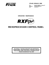
The RWB II PLUS compressor is controlled by a state-of-
the-art microprocessor control system. The microprocessor
continuously monitors the compressor unit’s condition and
operation. The microprocessor also directs instructions to
the various compressor unit subsystems.
The microprocessor has a membrane switch keyboard.
Pressing the keyboard in the area outlined as a key will cause
that function to be recognized by the microprocessor. The
keyboard has 32 membrane type keys.
In addition to the keyboard, there is an emergency stop but-
ton. Pushing the emergency stop will bypass the computer
and remove all power from the outputs.
This will shut down the compressor motor and all high volt-
age to the compressor auxiliary systems such as the oil
pump and liquid injection solenoid. THE EMERGENCY
STOP BUTTON IS FOR EMERGENCY SHUTDOWN SITU-
ATIONS ONLY and MUST NOT BE USED TO ROUTINELY
SHUT OFF THE COMPRESSOR.
The microprocessor continuously monitors the state of the
battery which maintains setpoints and various other data. If
the battery voltage is low, the message “LOW BATTERY”
will flash in the lower right hand corner of the bottom dis-
play (see S70-200 IOM for description of battery backup).
The microprocessor hardware contains an output watch-
dog circuit. If the microprocessor should fail, this circuit will
disable (turn off) all outputs.

RWB II PLUS MICROPROCESSOR CONTROL
OPERATION
S70-200 OM
Page 4
KEYS AND KEY FUNCTIONS
NOTE: The microprocessor will automatically return to
the main operating display after 60 seconds of keybo-
ard nonactivity.
The [CHANGE] key rotates the dual display screen through
six display modes. The [CHANGE] key is also used to change
the status of various setpoints.
The [STEP] key steps or moves a set of flashing brackets
through the variable setpoints on the Adjustable setpoints
display, the Auto-cycle display, the Security display and the
Setback display. The setpoint enclosed within the flashing
brackets may be changed or updated. The [STEP] key is
also used when the annunciator display is selected to step
through the annunciator’s four information displays.
NOTE: The [ * ] key is used to step or move the flashing
brackets, described above, backwards.
The [ENTER] key is used to enter new setpoint limits.
The [CLEAR] key will reset an alarm or cutout indication on
the annunciator screen and will clear the microprocessor to
allow continued operation or restarting if all conditions have
returned to normal and no other control lockouts are in force.
The [NUMERIC KEYPAD] is used to introduce new setpoint
limits.
The [+/-] key is used to toggle between pounds per square
inch gauge (g) and inches of mercury (hg).
The [RUN], [STOP], and [REMOTE START] keys control
the starting and stopping of the compressor unit.
The [ALARM SILENCE] key will de-energize the alarm horn
output.
The [AUTO], [REMOTE], and [MANUAL] keys control the
operation of the compressor slide valve and moveable slide
stop.
The [F1] function key will return the operator to the main
operating display. This function may be invoked at any time,
even during setpoint entry.
The [F2] function key will call up the Security display. NOTE:
Press the [F2] key, as prompted by the display, to return
to the previously selected display.
The [F3] function key will call up the Setback display. NOTE:
To exit the Setback display, press the [F1] key as
prompted by the display.
The [F4] function key will call up the Auto Cycle display.
NOTE: To exit the Auto Cycle display, press the [F1] key
as prompted by the display.
The [DISPLAY BACKLIGHT] key will toggle the dual LCD
display backlights on and off. A preset delay will shut off the
backlight after ten minutes elapsed time.
The microprocessor has two liquid crystal displays in an 8
line by 40 character format, for a total of 320 characters.
There are 9 different display modes. When power is first
applied to the control panel, the unit will be in the Operating
display mode. To change to a different display mode, press
the [CHANGE] key. The display modes in their order of rota-
tion are:
1. Operating display
2. Adjustable Setpoints display
3. Adjustable Setpoints display #2
4. Fixed Setpoints display
5. Annunciator display (4 pages)
6. Shutdown Record display
7. Freeze display
[F1] Operating display
[F2] Security display
[F3] Setback display
[F4] Auto Cycle display
NOTE: On initial powering of the microprocessor, and
any time power has been removed from the micropro-
cessor, only the Operating, Setpoints, Annunciator, and
Shutdown displays will display information. The freeze
display will appear as a dark screen. The Freeze display
will only be present after a compressor unit cutout and
power has not been interrupted to the microprocessor.
The cutout must be on a safety setpoint. When power is
lost to the micro, it will not show the freeze display.
OPERATING DISPLAY *
OPERATING DISPLAY: Thu 10-01-87 15:33:36
Suction Disch Oil Filter Compressor
20.0 g 180 g 170 g 01PSID MAN Mode
+015 F 140 F 135 F RUNNING
V Ratio S V Pos Pump %FLA Sep 132 F
4.6 090% OFF 080% HTR off
Auto D Auto L FORCED UNLD ALARM
C.C.=20.0 g LOW-BATTERY
*Display for illustrative purposes only.
The Operating display is continuously updated and provides
a variety of information in regard to the current status of the
compressor’s condition and performance.
The information furnished by the Operating display is as fol-
lows:
The DAY, DATE, and TIME are displayed at the top right of
the display.
NOTE: To set day, date, and time; see TO CHANGE THE
ADJUSTABLE SETPOINTS.
SUCTION - Suction Pressure and Temperature are mea-
sured at the compressor inlet and are, respectively, displayed
in pounds per square inch gauge (g) or inches of mercury
(hg) and degrees Fahrenheit.
DISCH - Discharge Pressure and Temperature are measur-
ed at the compressor outlet and are, respectively, displayed
in pounds per square inch gauge (g) and degrees Fahrenheit.
OIL - Oil Pressure and Temperature are measured prior to
entering the compressor and are, respectively, displayed in
pounds per square inch gauge (g) and degrees Fahrenheit.
FILTER - Pressure drop across the oil filter. On the model
676 only, the bearing oil filter pressure drop is displayed.
The main oil injection feed filter pressure drop is shown on a
unit mounted gauge.

RWB II PLUS MICROPROCESSOR CONTROL
OPERATION S70-200 OM
Page 5
COMPRESSOR - Compressor displays the status of the
compressor unit. The mode of operation will be indicated as
either manual (MAN MODE) when the [RUN] key has been
pressed, automatic (AUTO MODE) when Auto Cycle has
been activated, remote (RMT MODE) when the [REMOTE]
key has been pressed, or off (OFF MODE).
V RATIO - Volume Ratio is the ratio selected by the micro-
processor to provide the highest efficiency at any given suc-
tion and discharge pressure condition. Immediately below
this, an information space has been provided to indicate
whether V ratio is in the automatic (AUTO) or the manual
(MAN) mode. The microprocessor will control this function
only in the automatic mode. To the right of the mode indica-
tor, two other messages may appear:
I - Indicates V Ratio increase.
D - Indicates V Ratio decrease.
SV POS - Slide valve position is displayed as a percentage.
This percentage reflects the mechanical position of the slide
valve and does not reflect the percentage of full load opera-
tion. Immediately below this information, space has been
provided to indicate whether SV Pos is in the automatic
(AUTO), manual (MAN), or remote (RMT) mode. The micro-
processor will control this function in the automatic mode.
To the right of the mode indicator, two other messages may
appear:
L - Indicates Slide Valve loading.
U - Indicates Slide Valve unloading.
PUMP - Pump displays the current status of the oil pump.
The display will read ON or OFF whenever the HAND-OFF-
-AUTO switch is selected to AUTO and the compressor is
running.
% FLA - Percent Full Load Amps displays the percentage of
the drive motor full load amperage rating that the motor is
currently using.
SEP - Separator displays the oil separator temperature in
degrees Fahrenheit.
HTR - Heater displays the condition of the oil separator
heater(s), indicating ON or OFF.
ALARM/CUTOUT - An Alarm or Cutout message indicates
an Alarm or Cutout setpoint has been reached, or exceeded.
Rotate the display mode to the Annunciator display for de-
tails. In the event of a cutout, rotate to the Freeze display for
further details.
FORCED UNLD - A Forced Unload message indicates that
the percentage of motor full load amps has exceeded the
maximum limit and the microprocessor is unloading the com-
pressor until the percentage FLA falls back to normal limits.
RECYCLE DELAY - A Recycle Delay message indicates
that the compressor has started and has shut down within
the time delay set point period. The Recycle Delay will pre-
vent the compressor from starting until the delay time ex-
pires and is intended to prevent damage to the compressor
motor from successive restarts. During Recycle Delay, the
microprocessor will alternatively flash “RECYCLE DELAY”
and the remaining delay time in minutes.
NOTE: Consult Motor Manufacturer for the recom-
mended duration of the Recycle Delay.
If the [RUN] key is pushed while the
unit is in Recycle Delay, the com-
pressor will start at the end of the
delay period.
C.C. - Capacity Control, located at the bottom left of the
display, indicates the current capacity control suction pres-
sure setpoint in pounds per square inch gauge (g) or inches
of mercury (hg).
ADJUSTABLE SETPOINTS DISPLAY *
ADJUSTABLE SETPOINTS: ID=[33] [10-01-87]
Cap. Control---[20.0 g ] Thu [15:33:36]
Lo Suct Cutout-[12.0 g ] Baud----[ 2400]
Lo Suct Alarm--[16.0 g ]
Hi Disch Cutout-[225 g ] Aux1[Alarm][NO]
Hi Disch Alarm--[215 g ] Aux2[Shutd][NC]
M.L.C. Stop Load--[095%] CT Factor-[078]
M.L.C. Force Unld-[100%] Recy.Delay-[30]
The Adjustable Setpoints display lists the adjustable set-
points which define the limits of the compressor package
operation. When these limits are reached, or exceeded,
an
alarm or compressor shutdown will occur. The informa
tion fur-
nished by the Adjustable Setpoints display is as follows:
CAP CONTROL - The Capacity Control setpoint, reported
in pounds per square inch gauge (g) or inches of mercury
(hg), controls the loading and unloading of the compressor
when SV POS is in the automatic (AUTO) mode.
LO SUCT CUTOUT - The Low Suction Pressure Cutout, re-
ported in pounds per square inch gauge (g) or inches of
mercury (hg), will shut down the compressor if the suction
pressure drops to this limit, or lower, for 120 seconds or longer.
LO SUCT ALARM - The Low Suction Pressure Alarm, re-
ported in pounds per square inch gauge (g) or inches of
mercury (hg), will trigger a prealarm if the suction pressure
drops to this limit, or lower.
HI DISCH CUTOUT - The High Discharge Pressure Cutout,
reported in pounds per square inch gauge (g), will shut down
the compressor if the discharge pressure equals, or exceeds,
this setpoint.
HI DISCH ALARM - The High Discharge Pressure Alarm,
reported in pounds per square inch gauge (g) will trigger a
pre-alarm if the discharge pressure equals, or exceeds, this
setpoint.
M.L.C. STOP LOAD - The Motor Load Control Stop Load,
reported as a percentage of the motor full load amps (FLA),
will prevent the compressor slide valve from loading when
the setpoint is equaled, or exceeded. NOTE: Consult mo-
tor nameplate for recommended setpoint.
M.L.C. FORCE UNLD - The motor Load Control Force Un-
load, reported as a percentage of the motor full load amps
(FLA), will force the compressor to unload until the motor
full load amps (FLA) fall within 1% of the setpoint, or lower.
NOTE: Consult motor nameplate for recommended set-
point.
*Display for illustrative purposes only.

RWB II PLUS MICROPROCESSOR CONTROL
OPERATION
S70-200 OM
Page 6
Cycle Time - Cycle time is the amount of time between the
beginning of each load/unload response. Ten seconds is
the default value. “Cycle Time” is adjustable between 5 and
30 seconds in 5 second intervals. The “Step” key is used to
select a setpoint; then press the “Change” key to toggle
through the selections.
Low % FLA - This setpoint is used to determine if the cou-
pling has broken. 20% is the default value. It is adjustable
from 0 to 100% FLA. Use the “Step” key to select a setpoint;
then enter the desired setpoint and press the “Enter” key.
TO CHANGE THE ADJUSTABLE SETPOINTS:
Adjustable Setpoints are stored in RAM (random access
memory) and are easily changed in the field.
Adjustable Setpoints are lost if
power is interrupted and the battery
is not fully charged. To facilitate re-
entry, we suggest that a list of Adjustable Setpoints be
affixed to one end of the microprocessor cabinet for
reference. For your convenience, a blank Adjustable set-
points display which may be photocopied has been provided
(See page 10).
NOTE: The following procedure also applies to the chang-
ing of the Security, Setback, and Auto Cycle display set-
points.
1. Press the [CHANGE] key to rotate the display to the Ad-
justable Setpoints display.
2. Press the [STEP] key to move or step a set of flashing
brackets through the various setpoints. A setpoint is selected
for change or update when it is enclosed by the flashing
brackets.
NOTE: The DAY indicator, itself, will flash when selected
for change or update.
3. Having selected the setpoint to be changed, the [NU-
MERIC KEYPAD] may be used to enter the new setpoint.
NOTE: All digits must be entered, including zeros. For
example, (01.0).
NOTE: The DAY, AUX 1, and AUX 2 setpoints, once selected,
are changed or updated by pressing the [CHANGE] key.
NOTE: Certain setpoints may be reported in either pounds
per square inch gauge (g) or inches of mercury (hg). To
toggle between (g) and (hg), having selected the setpoint,
press the [+/-] key to toggle between (g) and (hg).
4. In the event that an incorrect setpoint is keyed in all or
part, press the [CLEAR] key to restore the original setpoint.
Pressing the [CLEAR] key a second time will eliminate the
flashing brackets.
5. Having keyed the desired setpoint, press the [ENTER]
key. The new setpoint will be entered and the flashing brack-
ets will move or step to the next setpoint.
NOTE: A setpoint entry outside the parameters of the
Adjustable Setpoint display will be refused and the origi-
nal Adjustable setpoint will be restored.
NOTE: To clear any time values [STEP] to the desired
setpoint, press [CHANGE] and then press [CLEAR].
ID - The ID number is a programmable identification code
used in telecommunications to access a specific compres-
sor.
DATE - The Date displays the current date in the following
format: Month - Day - Year.
DAY - Day will display the current day of the week.
TIME - The Time displays the current time in the following
format: Hours - Minutes - Seconds. The time is in 24:00:00
hour clock format.
BAUD - Shows the baud rate of the RS422 communication
ports 1 and 2. Both ports are configured as follows: word = 8
bit, parity = none or even, stop = 1 bit. The communications
ports are programmable from 300 to 19200 baud.
AUX 1 and AUX 2 - May be configured for either an alarm or
shutdown and with either a normally closed (NC) or nor-
mally open (NO) contact.
CT FACTOR - The Current Transformer Factor records the
proper current transformer factor to match the compressor
motor FLA rating to the current transformer primary rating.
The CTF factor is programmable and its correct value is
determined by the following formula:
CTF = 1024 x FLA (Full Load Amps)
10 x CT (Current Transformer Primary Amps)
EXAMPLE: FLA = 230 Amps
CT = 300 (300:5)
CTF = 1024x 230 = 78 (Round to whole number)
10 x 300
RECY. DELAY - The Recycle Delay displays the current
recycle delay setpoint in minutes. NOTE: Consult motor
manufacturer for recommended setpoint.
ADJUSTABLE SETPOINTS PAGE 2 *
ADJUSTABLE SETPOINTS Page 2:
Start Diff Press--[100g]
Dead Band--[1.0#]
Prop. Band-[10 %]
Cycle Time-[10 sec]
Low % FLA--[020 %]
Dead Band - This is a + (plus) or - (minus) value above or
below the setpoint at which the compressor will neither load
nor unload. A dead band of 1 is the default value. It is
adjustable between .5 lbs. to 5 lbs. in increments of .5. The
“Step” key is used to select this setpoint; then press the
“Change” key to toggle through the selections.
Proportional Band - This setpoint is used to determine the
amount of time the load/unload solenoid is energized, ac-
cording to how far from the setpoint the actual control pres-
sure is. The smaller the number, the longer a load/unload
signal will be sent. 10% is the default value. Selections are
2, 5, 10, 15, 20, or 25%. The “Step” key is used to select this
setpoint; then press the “Change” key to toggle through the
selections.
*Display for illustrative purposes only.

RWB II PLUS MICROPROCESSOR CONTROL
OPERATION S70-200 OM
Page 7
PRELUBE, FULL LUBE, or CYCLING - Pump type will be
indicated.
PGM/ - Microprocessor Program version.
LIQ INJ CON - The Liquid Injection Control, reported in de-
grees Fahrenheit, will shut off the liquid refrigerant supply
to the compressor if the oil temperature equals or falls be-
low this setpoint.
FILTER - The Oil Filter setpoint will trigger an alarm when
the differential pressure across the oil filter equals or ex-
ceeds 25 pounds per square inch (PSI) for 15 seconds, or
longer.
OIL HEATER - The Oil Heater setpoint, reported in degrees
Fahrenheit, turns on the oil separator heater(s) when the oil
temperature equals or falls below this setpoint whenever
the compressor is NOT running.
Compressor Differential Cutout - The differential cutout
has been lowered from 55 lb to 25 lb. Cutout will occur after
five minutes. To allow operation at low differential pressures,
the micro will take the following steps:
A. Force unload the compressor to 50% and display an "F
Unload" when the oil pressure is within 10 lb of the main oil
injection port pressure and the slide valve position is greater
than 50%.
B. Prohibit the compressor from loading and display a "Ld
Inhib" message when the differential is within 15 lb of the
main oil injection port pressure.
Oil Pressure Alarm and cutout - Logic has been revised
to same logic as currently used on RXB/RXF. The new logic
is as follows:
Prelube and Cycling Oil Pump version when pump is not
running. Alarm will occur if oil pressure is 25 lb below dis-
charge pressure or within 10 lb of suction pressure for 30
seconds. Cutout occurs if oil pressure is 30 lb below dis-
charge pressure or if oil pressure is within 7 lb of suction
pressure for 10 seconds and alarm has already been set.
Full Lube and Cycling Oil Pump version when oil pump is
running. Alarm occurs if oil pressure is within 10 lb of dis-
charge pressure for 30 seconds. Cutout occurs when oil
pressure is within 5 lb of discharge pressure for 10 seconds
and oil pressure alarm has been set.
Cycling Oil Pump Control - The oil pump will cut off when
differential pressure between suction and discharge pres-
sure is 55 lb or greater. Upon pump termination the above
cutout logic (pump not running) is utilized. Pump cut-in oc-
curs when the differential pressure between suction and dis-
charge is 45 lb or less. Oil pressure alarm and cutout logic
(pump running) begins after a 30 second delay which al-
lows the oil pump to build pressure.
HOW TO DETERMINE
ADJUSTABLE SETPOINTS:
Adjustable Setpoints should reflect values compatible with
normal system operation. Too high a Low Suction Pressure
Alarm setpoint may cause nuisance prealarms. Similarly,
cutout setpoints should not fall within what are considered
normal plant operation. As a rule of thumb, set the Low Suc-
tion Pressure Alarm 5 PSIG lower than the lowest normal
suction pressure. The Low Suction Pressure Cutout should
be 5 to 10 PSIG lower than the Low Suction Pressure Alarm
setpoint.
The High Discharge Pressure Cutout should be set at 90%
of the setting of the lowest high side relief valve. The High
Discharge
Pressure Alarm should be set 10 PSIG lower than
the Cutout.
The Capacity Control setpoint should be the equivalent of
the normal suction condition.
FIXED SETPOINTS DISPLAY *
FIXED SETPOINTS: HIGH STAGE PRELUBE
OIL PUMP PGM/A
Hi Disch Cut----[212F]
Hi Disch Alarm--[194F] Liq Inj Con 113F
Hi Oil Temp Cut-[167F] Filter------[25]
Hi Oil Temp Alarm[158F]Oil Heater[113F]
Lo Oil Temp Cut--[49F] Lo Oil Cut-[030]
Lo Oil Temp Alarm[58F] Lo Oil Alrm[025]
The Fixed Setpoints display lists all fixed setpoints, program
version, plus low oil alarm and low oil cutout setpoints. Fixed
Setpoints define the limits of acceptable compressor opera-
tion. Fixed Setpoints are factory determined, stored in pro-
grammed memory (PROM), and will remain in memory if
power to the microprocessor is interrupted.
HI DISCH CUT - The High Discharge Temperature Cutout,
reported in degrees Fahrenheit, will shut down the com-
pressor if the discharge temperature equals or exceeds this
setpoint.
HI DISCH ALARM - The High Discharge Temperature Alarm,
reported in degrees Fahrenheit, will trigger a prealarm if the
discharge temperature equals or exceeds this setpoint.
HI OIL TEMP CUT - The High Oil Temperature Cutout, re-
ported in degrees Fahrenheit, will shut down the compressor
if the oil temperature equals or exceeds this setpoint.
HI OIL TEMP ALARM - The High Oil Temperature Alarm,
reported in degrees Fahrenheit, will trigger a prealarm if the
oil temperature equals or exceeds this setpoint.
LOW OIL TEMP CUT - The Low Oil Temperature Cutout,
reported in degrees Fahrenheit, will shut down the com-
pressor if the separator oil temperature equals or falls be-
low this setpoint.
LOW OIL TEMP ALARM - The Low Oil Temperature Alarm,
reported in degrees Fahrenheit, will trigger a prealarm if the
separator oil temperature equals or falls below this setpoint.
HIGH STAGE or BOOSTER - Compressor application indi-
cator. *Display for illustrative purposes only.

RWB II PLUS MICROPROCESSOR CONTROL
OPERATION
S70-200 OM
Page 8
ANNUNCIATOR DISPLAY *
ANNUNCIATOR: PG-1 Thu 10-01-87 15:33:36
(Use STEP key to advance PAGE)
High Press. Cutout *********************
High Press. Alarm *********************
Low Press. Cutout *********************
Low Press. Alarm *********************
Oil Press. Cutout *********************
Oil Press. Alarm *********************
ANNUNCIATOR: PG-2 Thu 10-01-87 15:33:36
(Use STEP key to advance PAGE)
Hi Oil Temp Cutout *********************
Hi Oil Temp Alarm *********************
Low Temp Cutout *********************
Low Temp Alarm *********************
Disch. Temp Cutout *********************
Disch. Temp Alarm *********************
ANNUNCIATOR: PG-3 Thu 10-01-87 15:33:36
(Use STEP key to advance PAGE)
Comp. Auxiliary *********************
Pump Auxiliary *********************
Oil Level *********************
Comp. Differential *********************
Dirty Filter *********************
ANNUNCIATOR: PG-4 Thu 10-01-87 15:33:36
(Use STEP key to advance PAGE)
Aux. 1 (Alarm) *********************
Aux. 2 (Shutdown) *********************
Low Motor Amps
Sensor Fault
When a prealarm or cutout occurs, a flashing ALARM or
CUTOUT indicator will appear in the lower right hand cor-
ner of the Operating display. To determine the fault, rotate to
the Annunciator display by pressing the [CHANGE] key.
The Annunciator display lists all key operative points on four
sequential displays. These displays can be rotated from page
#1 through page #4 by pressing the [STEP] key. When a
prealarm or cutout is triggered, the pertinent point will flash,
and the time of the occurrence will be recorded to the right
of the alarm. Prealarms are self-clearing. At this time the
alarm will stop flashing, but the time of the first occurrence
will still be recorded to the right of the alarm. Pressing the
[CLEAR] key while at the Annunciator display will clear all
alarms and/or cutouts.
In order to restore the Annunciator display and resume nor-
mal operation it will be necessary to go through the follow-
ing steps:
1. Correct the conditions causing the alarm.
2. Press the [ALARM SILENCE] key. (This action may pre-
cede correcting the conditions causing the alarm).
3. To clear or reset the Annunciator pages, press the
[CLEAR] key. This will also clear the ALARM or CUTOUT
indicator from the Operating display.
4. Press [F1] to call up the Operating display. If the condi-
tions causing the alarm have not been corrected or a new
fault has occurred, a new ALARM or CUTOUT message will
appear.
NOTE: Use of the Emergency Stop Button may trip one
or more alarm setpoints.
SHUTDOWN RECORD DISPLAY *
SHUTDOWN RECORD: Thu 10-01-87 15:33:36
(Use STEP key to advance PAGE)
Hi Oil Temp Cutout Wed 09-30-87 16:22:54
Comp Auxiliary Sat 08-22-87 09:47:02
Low Temp Cutout Thu 08-20-87 11:17:33
Pump Auxiliary Mon 08-17-87 18:53:11
Disch. Temp Cutout Tue 07-14-87 06:22:09
Oil Pres Cutout Fri 07-08-87 14:06:21
The Shutdown Record display keeps a record of the last six
shutdowns (cutouts). This information will help troubleshoot
persistent operational problems. The most recent cutout will
appear on the top line of the display with the oldest appearing
on the last or bottom line. When a cutout occurs, all informa-
tion is moved down one line and the new cutout appears at
the top. When the display is full, the oldest record is dropped
off the display and is not retained in memory. The informa-
tion presented is echoed from the Annunciator display; pro-
viding the type of cutout, the day, the date, and the time.
NOTE: This information will not be lost due to power
failure. FREEZE DISPLAY *
FREEZE DISPLAY: Thu 10-01-87 15:33:36
Suction Disch Oil Filter Compressor
20.0 g 225 g 170 g 01PSID OFF Mode
+015 F 140 F 135 F RECYCLE
V Ratio S V Pos Pump %FLA Sep 132 F
4.6 090% OFF 080% HTR off
Auto Auto CUTOUT
C.C.=20.0 g
The Freeze display has the same appearance and contains
the same information as the Operating display. (For a de-
scription of the information presented by the Freeze display,
refer to the Operating display.) The Freeze display freezes
the information of the Operating display AT THE MOMENT
OF A COMPRESSOR CUTOUT. The information on the
Freeze display can help the operator to identify the cause of
a fault which occurred when no one was present. The Freeze
display will retain the information generated by a cutout un-
til a new cutout occurs or power is removed from the micro-
processor.
Do not confuse the Freeze display
with the Operating display. In order
to avoid confusion remember that
the displayed information on the Operating display is
constantly being updated and changed. The Freeze dis-
play is fixed and FREEZE DISPLAY appears in the upper
left hand corner of the display.
NOTE: The Freeze display will appear as a blank screen
when power is initially furnished to the unit, and it will
return to a blank screen anytime power is removed from
the microprocessor.
*Display for illustrative purposes only.

RWB II PLUS MICROPROCESSOR CONTROL
OPERATION S70-200 OM
Page 9
*Display for illustrative purposes only.
SECURITY DISPLAY *
SECURITY DISPLAY: Thu 10-01-87 15:33:36
Setpoints Access---[Enabled ] Keyboard
Enter Access Code---[*****]
Press F2 To Exit
The [F2] function key will call up the Security display. The
Security display allows the operator to either enable or dis-
able the microprocessor’s keyboard and, thereby, prevent
unauthorized tampering with the various adjustable setpoints.
When enabled, the microprocessor keyboard is fully opera-
tive and the security lockout is not in effect. When disabled,
the keyboard is rendered partially nonfunctional. All displays
will still be accessible through the keyboard. If any attempt
is made to enter new adjustable setpoints, however, the mi-
croprocessor will default to the Security display.
TO ENABLE THE KEYBOARD, press the [STEP] key so
that the brackets beside Enter Access Code flash, key the
proper five digit access code, and press [ENTER]. The Set-
points Access will toggle from disabled to enabled and ad-
justable set point entry is now possible.
TO DISABLE THE KEYBOARD, press the [F2] function key
to call up the Security display. Press the [STEP] key until
the brackets beside Enter Access Code flash, key the proper
five digit access code, and press [ENTER]. Now, press the
[STEP] key until the brackets beside Setpoints Access flash
and press the [CHANGE] key to toggle from enabled to dis-
abled.
TO CHANGE THE ACCESS CODE, press the [F2] function
key to call up the Security display. Press the [STEP] key
until the brackets beside Enter Access Code flash, key the
proper five digit access code, and press [ENTER]. Now,
select the Enter Access Code a second time by pressing
the [STEP] key until the brackets beside Setpoints Access
flash, key in the new five digit access code, and press [EN-
TER].
NOTE: Power loss will not effect the Security display.
NOTE: IF NO ACCESS CODE WAS ENTERED AND THE
DISABLED COMMAND WAS SELECTED, THE ACCESS
CODE IS [00000].
LOST OR FORGOTTEN ACCESS CODE: Consult Frick
Company for assistance.
SETBACK DISPLAY *
SETBACK DISPLAY: Thu 10-01-87 15:33:36
Press F1 To Exit
Setback Setpoint-[05.0 g ] Active-[No ]
Start Stop Start Stop
Mon-[--:--]-[06:00] Fri-[16:00]-[--:--]
Tue-[--:--]-[--:--] Sat-[--:--]-[--:--]
Wed-[--:--]-[--:--] Sun-[--:--]-[--:--]
Thu-[--:--]-[--:--]
The [F3] function key will call up the Setback display. The
Setback feature enables automatic operation at two sepa-
rate suction conditions on a preset time schedule. Having
entered the desired Setback setpoint, enter the start and
stop time or times, and select Active: (Yes) or (No).
NOTE: To change the Setback setpoints, refer to “TO
CHANGE THE ADJUSTABLE SETPOINTS”
AUTO CYCLE DISPLAY *
AUTO CYCLE Thu 10-01-87 16:33:36
DISPLAY: Press F1 To Exit
Suction Pressure--------[20.0 g ]
Compressor Start--------[20.0 g ]
Compressor Stop---------[18.0 hg]
Minimum Slide Valve-----[00%]
Auto Cycle Active-------[No ]
The Auto Cycle display provides for independently adjus-
table setpoints to turn the compressor on and off in response
to the suction pressure or as an adjustable setpoint to limit
the minimum slide valve position.
NOTE: To change the Auto Cycle setpoints, refer to
“TO CHANGE THE ADJUSTABLE SETPOINTS”
SUCTION PRESSURE - Constantly monitors and displays
the suction pressure in pounds per square inch gauge (g) or
inches of mercury (hg).
COMPRESSOR START - Compressor Start-up will bring
the compressor back on line when the suction pressure rises
to the displayed setpoint.
COMPRESSOR STOP - Compressor Stop will shut down
the unit if the suction pressure drops to or below the dis-
played setpoint limit. NOTE: This limit must be set higher
than Low Suction Pressure Cutout and the Low Suction Pres-
sure Alarm setpoints.
MINIMUM SLIDE VALVE - Minimum Slide Valve Position,
shown as a percentage, will limit the slide valve position to
the displayed setpoint.
AUTO CYCLE ACTIVE - Indicates whether Auto Cycle is
active (YES) or not active (NO). Press the [CHANGE] key
while at this setpoint to change the status. Upon deactiva-
tion, the compressor will return to the previous mode of op-
eration.
ANALOG OFFSET DISPLAY*
ANALOG OFFSET:
Suc Disch Oil Sep Filt Spare Econ
Temp +0 +0 +0 +0 +0.0
Pres +0.0 +0 +0 +0 +0
Channel 10 12 13
Press +0 +0 0
The Analog Offset Display is accessed by pressing +/- key.
All analog values can be offset + or - 3 to 9 units depending
on which value is being adjusted. Use the [STEP] key to
step to the desired setpoint. Press the [CHANGE] key to
change the value of the offset by 1. The actual analog value
will be displayed on the top line of the display. The “Econ”
and channels 10, 12, 13 are displayed but do not pertain to
the standard program.

RWB II PLUS MICROPROCESSOR CONTROL
OPERATION
S70-200 OM
Page 10
Sensor Fault Failure - A “Sensor Fault” cutout was added
to the program to stop the compressor if a temperature or
pressure sensor is at its minimum or maximum limit for 5
seconds. The following channels and conditions will cause
this cutout:
Channel 1 - Suction Temp Low or High (-67 to 113OF)
Channel 2 - Low or High Discharge Temp (32 or 212OF)
Channel 3 - Low or High Oil Temp (0 or 180OF)
Channel 4 - Low or High Separator Temp (0 or 180OF)
Channel 6 - Low or High Oil Pressure (<0 g or 285 g)
Channel 8 -
Low or High Discharge Pressure (<0 g or 285 g)
Channel 9 - Low Suction Pressure (29 hg only)
Pulse Load Signal at 100% Slide Valve Position - This
new feature will stop loading the compressor when 100%
slide valve is displayed. The load signal will pulse for 2 sec-
onds every minute when the slide valve is at 100% and the
pressure is above setpoint.
TEMPERATURE-PRESSURE CONTROL
PROGRAM (OPTION)
NOTE: The following displays are provided only when
the Temperature-Pressure Control Program option has
been ordered with the RWB II Plus Rotary Screw Com-
pressor Unit.
SETPOINTS DISPLAY PAGE 1 *
SETPOINTS PAGE 1 Capacity Control=Press
C.C. CUTOUT ALARM PB DB CT
Press 25.3g 01.3g 05.3g 10 1.0 10
Temp +40.0F +32.0F +33.0F 10 0.5 10
offset-act
Sup Heat-Alarm-10F-no
Sep Cond-Alarm-10F-no
* Display for illustrative purposes only.
The Setpoints Display is accessed by pressing the
[CHANGE] key.
CONTROL - This setpoint is used to select either Pressure
Capacity Control or Temperature Capacity Control. NOTE:
There are only two setpoints, press for pressure capac-
ity control and temp for temperature capacity control.
CC - The capacity control setpoint is for normal operation,
not setback.
CUTOUT -This setpoint will stop the compressor if the suc-
tion pressure drops below the pressure setpoint for 90 sec-
onds or if the CC Temperature drops below the temperature
setpoint. There is no time delay on the temperature cutout.
ALARM - An alarm will be activated if the suction pressure
drops below the pressure setpoint or if the CC Temperature
drops below the temperature setpoint. There is no time de-
lay for either.
PB - The Proportional Band (PB) is used to determine the
amount of time the load/unload solenoid is energized, ac-
cording to how far away from the setpoint the actual control
pressure or temperature is. The smaller the number, the more
load/unload will be sent. A PB of 10% is default. It is adjust-
able to 2, 5, 10, 15, 20, or 25 percent.
DB - The Dead Band (DB) is a + (plus) or - (minus) value
above or below the setpoint which the compressor will nei-
ther load nor unload. It is adjustable between .5 and 5.0
psig or degrees, in increments of .5 units.
CT - The Cycle Time (CT) setpoint is the amount of time
between the beginning of each load/unload response. It is
adjustable to 5, 10, 15, 20, 25, or 30 seconds.
Use the [STEP] key to step to the desired setpoint, then
press the [CHANGE] key to change the CC, PB, DB and CT
values. Enter the desire value for the remaining setpoints
and press [ENTER] when complete.
ADJUSTABLE SETPOINTS FORM
ADJUSTABLE SETPOINTS: ID = [ ] [ - - ]
Cap. Control ———[ ] Thu [ : : ]
Lo Suct Cutout ——[ ] Baud ———————[ ]
Lo Suct Alarm ———[ ]
Hi Disch Cutout ——[ ] Aux 1 [ ] [ ]
Hi Disch Alarm ——[ ] Aux 2 [ ] [ ]
M.L.C. Stop Load —[ ] CT Factor ———[ ]
M.L.C. Force Unld —[ ] Recy. Delay ——[ ]
Photocopy and fill in applicable data for your unit. Retain for reference if reentry is required.

RWB II PLUS MICROPROCESSOR CONTROL
OPERATION S70-200 OM
Page 11
TEMPERATURE-PRESSURE CONTROL
PROGRAM (OPTION) (continued)
The new setpoints provided on this display allow monitor-
ing of compressor superheat and condensing in the sepa-
rator. The following setpoints apply to the monitoring of the
superheat and condensing in the separator.
ALARM/(SHUTDOWN) -The Alarm/(shutdown) setpoints
select the conditions for an alarm or shutdown. If alarm is
selected, the alarm will occur after a 30 second delay. If
shutdown is selected, the shutdown will occur 60 seconds
after the alarm.
OFFSET - This setpoint is the degrees F above the satura-
tion point temperature where the alarm or shutdown will
occur.
ACT - The function selects whether the alarm/shutdown is
activated or not.
Use the [STEP] key to step to the desired setpoint, then
press the [CHANGE] key to change the setpoint. Press [EN-
TER] when all desired setpoint changes have been made.
SETBACK DISPLAY *
SETBACK DISPLAY: Tue 04-10-90 08:44:50
Press Setpoint-[25.3g ] F1 To Exit
Temp Setpoint—[+50.0F] Active-[No ]
Stop Start Start Stop
Mon-[—:—}-[—:—] Fri-[—:—]-[—:—]
Tue-[—:—}-[—:—] Sat-[—:—]-[—:—]
Wed-[—:—}-[—:—] Sun-[—:—]-[—:—]
Thu-[—:—}-[—:—]
The Setback Display is accessed by pressing the [F3] key.
PRESS SETPOINT - The capacity control setpoint used
when in the Setback mode and Pressure is selected as the
capacity control desired.
TEMP SETPOINT - The capacity control setpoint used when
in the Setback mode and Temperature is selected as the
capacity control desired.
NOTE: To change the Setback setpoints, refer to “TO
CHANGE THE ADJUSTABLE SETPOINTS”.
The Auto Cycle display provides for independently adjus-
table setpoints to turn the compressor on and off in response
to the suction pressure or as an adjustable setpoint to limit
the minimum slide valve position. The compressor can be
started and stopped by the following pressure setpoints even
if the capacity control is selected to temperature.
AUTO CYCLE PRESS CONTROL DISPLAY *
AUTO CYCLE PRESS Tue 04-10-90 08:44:57
DISPLAY: Press F1 To Exit
Suction Pressure--------[06.5 g ]
Comp Start - [99.0 g } Timer—[00 min]
Comp Stop— [29.0 hg] Timer—[00 min]
Min SV———[50%]
Active———[No ] * for Temp Menu
NOTE: To change the Auto Cycle setpoints, refer to “TO
CHANGE THE ADJUSTABLE SETPOINTS”
SUCTION PRESSURE - Constantly monitors and displays
the suction pressure in pounds per square inch gauge (g)
or inches of mercury (hg).
COMP START - The suction pressure must be greater than
or equal to the “START” setpoint in order to start the com-
pressor. This setpoint works in conjunction with the “TIMER”
setpoint located to the right of it on the display.
TIMER - This is a time delay used to start the compressor.
The timer only accumulates time whenever the pressure
rises to or above the “START” setpoint and will reset if the
pressure drops below the “START” setpoint.
COMP STOP - Compressor Stop will shut down the unit if
the suction pressure drops to or below the displayed “STOP”
setpoint limit. This setpoint works in conjunction with the
“TIMER” setpoint located to the right of it on the display.
NOTE: This limit must be set higher than Low Suction
Pressure Cutout and the Low Suction Pressure Alarm
setpoints.
(STOP) TIMER - The (stop) TIMER is a time delay used to
stop the compressor. The timer only accumulates time when-
ever the pressure drops to or below the “STOP” setpoint
and will reset if the pressure rises above the “STOP” set-
point.
MINIMUM SLIDE VALVE - Minimum Slide Valve Position,
shown as a percentage, will limit the slide valve position to
the displayed setpoint.
ACTIVE - Indicates whether Auto Cycle is active or not. Press
the [CHANGE] key while at this setpoint to change the sta-
tus. Upon deactivation, the compressor will return to the
previous mode of operation.
AUTO CYCLE TEMP CONTROL DISPLAY *
AUTO CYCLE TEMP Tue 04-10-90 08:45:40
DISPLAY: Press F1 To Exit
Cap Control Temperature—[+50.5 F]
Comp Start-[+50.0 F] Timer—[01 min]
Comp Stop—[+20.0 F] Timer—[01 min]
Min SV——[50%]
Active——[Yes] * for Press Menu
The Auto Cycle Temperature Control Display is accessed
by pressing F4 and then the * keys. NOTE: The compres-
sor can be started and stopped by the following tem-
perature setpoints even if the capacity control is se-
lected to pressure.
CAP CONTROL TEMPERATURE - Constantly monitors and
displays the suction temperature.
COMP START - The CC (capacity control) Temperature must
*Display for illustrative purposes only.

RWB II PLUS MICROPROCESSOR CONTROL
OPERATION
S70-200 OM
Page 12
be greater than or equal to the “START” setpoint in order to
start the compressor. This setpoint works in conjunction with
the “TIMER” setpoint located to the right of it on the display.
(Start) TIMER - This is a time delay used to start the com-
pressor. The timer only accumulates time whenever the CC
Temperature rises to or above the “START” setpoint and will
reset if the CC Temperature drops below the “START”
setpoint.
COMP STOP - The CC Temperature must be less than or
equal to the “STOP” setpoint in order to stop the compres-
sor. This setpoint works in conjunction with the “TIMER” set-
point located to the right of it on the display.
(STOP) TIMER - The (stop) TIMER is a time delay used to
stop the compressor. The timer only accumulates time when-
ever the CC Temperature drops to or below the “STOP” set-
point and will reset if the CC Temperature rises above the
“STOP” setpoint.
MINIMUM SLIDE VALVE - Minimum Slide Valve Position,
shown as a percentage, will limit the slide valve position to
the displayed setpoint.
ACTIVE - Indicates whether Auto Cycle is active or not. Press
the [CHANGE] key while at this setpoint to change the sta-
tus. Upon deactivation, the compressor will return to the
previous mode of operation.
LEAD-LAG OPTION
The lead-lag compressor sequencing option provides the
controls for operating two RWB II compressors in one system.
AUTO CYCLE DISPLAY *
AUTO CYCLE Tue 04-10-90 08:44:57
DISPLAY: Press F1 To Exit
Suction Pressure--------[06.5 g ]
Comp Start - [99.0 g } Timer—[00 min]
Comp Stop— [29.0 hg] Timer—[00 min]
Min SV———[50%] Lead—[YES]
Active———[No ]
*Display for illustrative purposes only.
The software includes user adjustable setpoints on the Auto
Cycle setpoints screen (F4 on Main Menu) for the following:
START - The suction pressure must be greater than or equal
to the “START” setpoint in order to start the compressor.
This setpoint works in conjunction with the “Timer” setpoint
located to the right of it on the Auto Cycle setpoints screen.
TIMER - This is a time delay used to start the compressor.
The timer only accumulates time whenever the pressure rises
to or above the “START” setpoint and will reset if the pres-
sure drops below the “START” setpoint.
STOP - The suction pressure must be less than or equal to
the “STOP” setpoint in order to stop the compressor. This
setpoint works in conjunction with the “Timer” setpoint lo-
cated to the right of it on the Auto Cycle setpoints screen.
TIMER - This is a time delay used to stop the compressor.
The timer only accumulates time whenever the pressure
drops to or below the “STOP” setpoint and will reset if the
pressure rises above the “STOP” setpoint.
MIN SV -This setpoint is the minimum slide valve position,
shown as a percentage, it will limit the slide valve position to
the displayed setpoint.
LEAD - This setpoint assigns the compressor as the lead or
the lag unit. Press the [CHANGE] key while at this setpoint
to change the status.
ACTIVE - This setpoint indicates whether the Auto Cycle
Mode is active or not. Press the [CHANGE] key while at this
setpoint to change the status.
OPERATION
For operation of the LEAD-LAG sequence, both units must
be in Auto Cycle compressor mode, one compressor micro
selected as the LEAD compressor, the other compressor
selected as the LAG compressor and the slide valves in Auto
mode.
With NO Compressor Running
The lead will start when its “START” setpoint is reached for
the amount of time selected for the “TIME” setpoint.
With ONE Compressor Running
If the load rises:
The lag compressor will start when its “START” setpoint is
reached for the amount of time selected for the “TIME” set-
point and the lead compressor is running at 100% slide valve
or running with the motor load inhibit or lead cutout or lead
in recycle.
If the load falls:
The lead compressor will stop when its “STOP” setpoint is
reached for the amount of time selected for the “TIME”
setpoint.
With TWO Compressors Running
If the load rises:
The lead and lag compressor will load independently.
If the load falls:
The lag compressor will unload to its “MIN SV” setpoint. Then
the lead compressor will unload to its “MIN SV” setpoint.
The lag compressor will stop when the suction pressure
drops below the “STOP” setpoint for the amount of time se-
lected for the “TIME” setpoint.
NOTE: Be careful not to select both compressors as lead
compressors or as lag compressors as improper op-
eration will result.
NOTE: One compressor will operate as a normal auto
cycle compressor when any one of the following occurs:
a. Power is removed from one of the two compressors,
b. Either of the compressors is NOT selected to “AUTO”,
or
c. If communications is lost between the compressors for
any reason.

RWB II PLUS MICROPROCESSOR CONTROL
OPERATION S70-200 OM
Page 13
COMMUNICATIONS TROUBLESHOOTING
Troubleshooting the communications:
Go to the FIXED SETPOINTS PAGE by using the “CHANGE”
key and the “ * ” key. The display will appear as:
FIXED SETPOINTS DISPLAY *
FIXED SETPOINTS: HIGH STAGE PRELUBE
COMM ACTIVITY—[ ] OIL PUMP PGM/A
Hi Disch Cut----[212F]
Hi Disch Alarm--[194F] Liq Inj Con 113F
Hi Oil Temp Cut-[167F] Filter------[25]
Hi Oil Temp Alarm[158F]Oil Heater[113F]
Lo Oil Temp Cut--[49F] Lo Oil Cut-[030]
Lo Oil Temp Alarm[58F] Lo Oil Alrm[025]
If the microprocessor is receiving information in the com-
munications port from the other compressor, a “2” will flash
between the brackets. During normal operation a “2” will flash
every 5 seconds.
At the same time information is display on the lower right
hand corner of the Auto Cycle display concerning the lead-
lag information:
AUTO CYCLE DISPLAY *
AUTO CYCLE Tue 04-10-90 08:44:57
DISPLAY: Press F1 To Exit
Suction Pressure--------[06.5 g ]
Comp Start - [99.0 g } Timer—[00 min]
Comp Stop— [29.0 hg] Timer—[00 min]
Min SV———[50%] Lead—[YES]
Active———[No ] 0111 111
This information is either “0” or “1” and represents what is
being sent from the other compressor. Consult Frick Com-
pany if additional information is required.
HOW THE MICROPROCESSOR WORKS
- SUMMARY -
The Frick microprocessor has 4 major components and a
variety of sensors. The major components are the SBC
(single board computer), two display screens, and the key-
board.
The SBC can be considered the brain of the microproces-
sor control console. The SBC contains the logic center which
provides the rules by which the microprocessor will oper-
ate, the integrated circuit chips which store the burned-in
memory of how the compressor unit is to behave, an analog
input to convert VDC from the various sensors into com-
puter binary language, and RAM (random access memory)
integrated circuit chips to store information which can be
readily changed by the microprocessor or, as in the case of
adjustable setpoints, by the operator. The SBC collects in-
formation, processes the information, and delivers instruc-
tions to the displays and to the output modules.
The SBC gathers information from several sources on the
compressor unit. Pressure transducers sense changes in
pressure and return a variable DC voltage of 1 to 5 VDC to
the SBC. The signals are converted into binary code which
the microprocessor understands. The microprocessor scans
the incoming data many times per second and compares
the information it receives with the instructions programmed
in the PROM chips, information stored in the RAM chips,
and instructions it has received from the console keyboard.
As operating conditions change, the microprocessor also
forwards the information it is receiving to the display screen.
When an operating condition or conditions develop which
the microprocessor program identifies as requiring a spe-
cific action, the microprocessor generates an instruction
which is forwarded to the output modules. The instruction
triggers a solid state output device capable of handling con-
trol voltage and the instruction is executed. In some cases,
such as load and unload instructions, the computer displays
the instruction on the Operating display with an L (load) or U
(unload) symbol at the same time as the appropriate output
is energized.
If the microprocessor receives information that indicates an
abnormal operating condition has been reached or is
present, it will generate one or more of the following instruc-
tions:
1. If a subsystem on the compressor unit, such as the oil
heater(s) or liquid injection, can correct the problem, the
microprocessor will energize or deenergize this system.
2. If a prealarm setpoint has been reached the micro-
processor will trigger the prealarm and display this informa-
tion on the Operating display and the Annunciator display.
3. If a cutout setpoint has been reached, the microproces-
sor will shut down the compressor. The microprocessor will
indicate CUTOUT on the Operating display and the infor-
mation present on the Operating display at the moment of
cutout will be stored and can be retrieved by rotating dis-
plays to the Freeze display. Additional information will be
available through the Annunciator and Shutdown Record
displays.
* Display for illustrative purposes only.
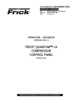
ARE ON THE SAME SKID
WIRED AT FRICK IF BOTH UNITS
DE-9P DE-9P
ON BOTH CONNECTORS
JUMPER PIN 1 TO 6 AND 2 TO 7
SBCSBC
WIRING FOR LEAD-LAG SEQUENCING
WITH DBCH-9 HOOD (2 THUS)
CONNECTORS-#DE-9P MALE
FROM ALL OTHER WIRING
RS 422 WIRING SHALL BE SEPARATE
COLOR CODING SHOWN IS BELDEN #8777
USE BELDEN #8777 OR EQUAL (3 TWISTED PAIRS)
BLK
RED
BLK
GRN 4
5
8
9
33
9
8
5
4
+RX +RX
+TX +TX
-RX -RX
-TX -TX
COM COM
UNIT "B"
PORT 2
RS422
UNIT "A"
PORT 2
RS422
OPTIONAL
NOTE: WHEN USING THE RS422 PORTS FOR LEAD-LAG, THEY
CANNOT BE USED FOR ANY OTHER COMMUNICATIONS.

RWB II PLUS MICROPROCESSOR CONTROL
OPERATION
S70-200 OM
Page 14
A typical example of how the microprocessor responds can
be illustrated by the responses generated by the micropro-
cessor as oil temperature increases. Assume that the ambi-
ent temperature and compressor unit temperature are 45OF
and you have just pressed the [RUN] key to start the com-
pressor unit:
AT 45O F.
The microprocessor receives information that the oil
temperature is below 49OF, the Low Oil Temperature Cutout
setpoint, and and shuts down the unit. The microprocessor
will prevent the compressor package from running. The
microprocessor also instructs the oil heater(s) output to ener-
gize the oil heater(s).
AT 50O F.
When the oil temperature reached 50OF the microprocessor
would allow the Low Oil Temperature Cutout to be cleared
and the compressor unit could now be started. (Assume that
the [RUN] key has been pressed and that the compressor
has now started.) The Low Oil Temperature Alarm would
still be engaged and cannot be cleared until oil temperature
exceeds 58OF. The oil heater(s) shut off on compressor start.
AT 113O F
The microprocessor instructs the liquid-injection solenoid
output to deenergize the liquid-injection solenoid.
AT 122O F
The microprocessor instructs the liquid-injection solenoid
output to energize.
AT 110O F TO 150O F.
Normal operating range. The microprocessor continues
monitoring oil temperature and reporting this information on
the Operating display.
AT 158O F.
The microprocessor triggers the High Oil Temperature Alarm
and displays the alarm on the Operating display and the
Annunciator display.
AT 167O F.
The microprocessor instructs the compressor motor to shut
down and displays a CUTOUT indication on the Operating
display. It stores the operating conditions at the moment of
cutout in the Freeze display. Information regarding the cut-
out will also be retained by the Annunciator and the Shut-
down Record displays.
NOTE: If the operator makes an error by attempting to
start the compressor under conditions outside safe
normal operating conditions, the microprocessor will
prevent start-up and advise the operator of the fault.
MULTIPLE COMPRESSOR SEQUENCING
FOR RWB II COMPRESSOR UNITS WITH
MICROPROCESSOR CONTROLS
A - The standard microprocessor panel includes:
1. Remote Run Input
2. Remote Load Input
3. Remote Unload Input
The remote run input is only recognized when the remote
run mode has been selected by pressing the “remote start”
key on the front panel of the microprocessor.
The remote load and unload inputs can only be recognized
when the “remote” key in the slide valve column on the front
panel of the microprocessor has been pressed.
B - If master sequencing between multiple compressors in
parallel on a common suction is desired. This output data
will permit the compressor microprocessor to be interfaced
with a master sequence controller. See electrical diagram
for details.
SUGGESTED PROGRAMMABLE
CONTROLLER PROGRAM TO DECODE
MICROPROCESSOR OUTPUT DATA CODES

RWB II PLUS MICROPROCESSOR CONTROL
OPERATION S70-200 OM
Page 15
OUTPUT NO.
TERMINAL NO.
MNEMONIC
Compressor Off
Running
Slide
Valve
Position
HEX
CODES
13
34
BIT
0
0
1
0
1
0
1
0
1
0
1
0
33
14
BIT
1
0
15
32
BIT
2
0
16
31
BIT
3
0
MEANING OUTPUT DATA CODE
Running with MLC Inhibit
Lockout on Recycle Delay
Cutout
Undefined
Undefined
1101 0011
1011 0111 1111
B
C
D
E
F
C - A master sequence controller must be installed to pro-
vide the signals to remote start and stop the compressors
and remote load and unload the compressors based on the
common suction pressure or other parameter and the com-
pressor status based on the optional microprocessor output
data feedback. The customer may supply his own master
sequencer panel (usually a programmable controller) or
Frick, can supply this sequencer if desired (contact Frick
Company for pricing).
MASTER SEQUENCE CONTROLLER (USUALLY
PROGRAMMABLE CONTROLLER) I/O
(TYPICAL FOR EACH COMPRESSOR)
RWB II COMPRESSOR
WITH MICROPROCESSOR
(TYPICAL FOR EACH COMPRESSOR)
INPUTS
OUTPUTS
RUN COMPRESSOR
LOAD COMPRESSOR
UNLOAD COMPRESSOR
SPARE
BIT 1
BIT 0
BIT 2
BIT 3
INPUTS
OUTPUTS
MASSEQ1
MICROPROCESSOR OUTPUT DATA CODE
A 3.5 K OHM, 10 watt resistor (RES) must be field installed, as shown below, when the 120 VAC outputs of the RWB II PLUS are
driving 120 VAC solid state input devices such as programmable controllers.
10%
20%
30%
40%
50%
60%
70%
80%
90%
100%
0
0
0
0
1
1
1
1
0
0
0
0
0
0
0
0
0
0
1
1
1
0
1
1
0
0
1
1
0
0
1
1
2
3
4
5
6
7
8
9
A
PROGRAMMABLE CONTROL
DATA CODE BIT 3
DATA CODE BIT 2
DATA CODE BIT 1
DATA CODE BIT 0
RES
NEUTRAL
OUTPUT
HOT
5
16
15
14
13
31
32
33
34
47
45
46
44
42
43
41
48
RES
RES
RES
PROGRAMMABLE CONTROL
PROGRAMMABLE CONTROL
PROGRAMMABLE CONTROL
OUTPUT
OUTPUT
OUTPUT

RWB II PLUS MICROPROCESSOR CONTROL
OPERATION
S70-200 OM
Page 16
MICROPROCESSOR
TELECOMMUNICATIONS
The following details are typical
and may or may not match the soft-
ware supplied on your compressor.
The telecommunications capabilities are continuously
being expanded and improved. Therefore, you MUST con-
sult FRICK Company for the exact details on your par-
ticular unit(s) before developing system software to in-
terface with your compressors.
The Frick RWB II PLUS Microprocessor comes with an on
board telecommunications interface. The telecommunica-
tions feature permits interfacing the microprocessor with a
modem, remote data communications terminal, or master
computer via RS-422 protocol. In the case of a modem, tele-
phone lines are used for the actual transmission of data
permitting communications from a remote location.
The components necessary to utilize the telecommunica-
tions feature will vary with the application. Information con-
cerning these items may be obtained from Frick Company,
Waynesboro, Pa.
COMMUNICATIONS PROTOCOL
SPECIFICATIONS:
All commands must be in ASCII (CAPS) to be recognized. A
compressor with an ID code of [00] is considered disabled.
ID Codes from [01] through [99] are valid and are recog-
nized by the microprocessor.
The following is a complete list of available command types:
COMMAND CODE and DESCRIPTION
I = Returns compressor status information.
R = Compressor start command.
S = Compressor stop command.
V = Compressor slide valve control command.
D = Compressors display screens command.
P = Return Pressures information.
T = Return Temperatures information.
A = Return full load amps information.
C = Enter Change setpoints mode.
The following is a detailed description of each command:
RETURN COMPRESSOR STATUS INFORMATION: #01I
# Start of command sequence.
01 Compressor ID code.
I Return Status information command.
RETURNED ANSWER, ie: 090RRRN340
Character Description
Position of returned data
1,2,3 Slide valve position.
4 Remote, Auto, Manual (slide valve)
5 Delay-recycle, Running, Off.
6 Rem, Man, Off, Auto (Compressor mode)
7 Cutout, Alarm, Normal.
8,9,10 Suction in PSIA.
(Carriage return, line feed.)
COMPRESSOR START COMMAND: #01R01
# Start command sequence.
01 Compressor ID code.
R Start compressor command.
01 ID code repeated for verification
NOTE: The compressor must be in the remote
start mode for this command to be executed.
Returned answer: A01
Character Description
Position of returned data
1 Acknowledge of command sent.
2,3 ID code of compressor.
(Carriage return, line feed.)
COMPRESSOR STOP COMMANDS: #01S01
# Start command sequence.
01 Compressor ID code.
S Stop compressor command.
01 ID code repeated for verification
NOTE: The compressor must be in the remote
start mode for this command to be executed.
RETURNED ANSWER: A01
Character Description
Position of returned data
1 Acknowledge of command sent.
2,3 ID code of compressor.
(Carriage return, line feed.)
SLIDE VALVE CONTROL COMMANDS: #01VLXX
#01VUXX
#01VS
# Start command sequence.
01 Compressor ID code.
V Compressor control command.
L Load Slide valve command.
U Unload slide valve command.
XX = 00 Turns selected output off.
XX = 01 to 15 Turns selected output on
for XX seconds.
XX = 99 Turns selected output on.
S Return slide valve position value.
If the command was #01VL00, then the load
slide valve output on compressor #1 would be
turned off. If the command was #01VL05, then
the load slide valve output on compressor #1
would be turned on for 5 seconds, and would
then automatically turn off. NOTE: the slide
valve must be in the remote mode for this
command to be executed.
RETURNED ANSWER (for L or U commands): A01
Character Description
Position of returned data
1 Acknowledge of command sent.
2,3 ID code of compressor.
(Carriage return, line feed.)
RETURNED ANSWER (for S command), ie. 090
1,2,3 Slide valve position.

RWB II PLUS MICROPROCESSOR CONTROL
OPERATION S70-200 OM
Page 17
COMPRESSOR DISPLAY SCREENS COMMAND: #01DXN
# Start command sequence.
01 Compressor ID code.
D Compressor control command.
X = 0 Operating display.
X = S Adjustable setpoints display.
X = D2 Adjustable setpoints Page 2.
X = X Fixed setpoints display.
X = R Shutdown record display.
X = F Freeze display.
X = C Autocycle display.
X = P Security display.
X = B Setback display.
X = + Analog offset display.
X = AN Annunciator display page “N”
N = 1 Display page #1. NOTE: “N” para-
N = 2 Display page #2. meter uses to
N = 3 Display page #3. access annunci-
N = 4 Display page #4. ator pages.
If the command was #01DA1, then the micro-
processor would dump the annunciator display
page number one. Display dumps consist of
336 characters each.
RETURN PRESSURES COMMAND: #01PX
# Start command sequence.
01 Compressor ID code.
P Return pressures command.
X = S Return suction pressure (PSIA).
X = D Return discharge pressure (g/hg).
X = O Return oil pressure (g).
X = F Return filter differential pressure.
X = A Return all pressures.
If the command was #01PS, then the micro-
processor would dump the suction pressure.
RETURNED ANSWER
XXX = 3 characters followed by a carriage
return, line feed.
If using the “A” command, then the returned
data would be:
XXXXXXXXXXXX = 12 characters followed by a
carriage return, line feed.
RETURN FULL LOAD AMPS COMMAND: #01A
# Start command sequence.
01 Compressor ID code.
A Return full load amps command.
If the command was #01A, then the micro
processor would dump the full load amps value.
RETURNED ANSWER:
XXX = 3 characters followed by a carriage
return, line feed.
RETURN TEMPERATURES COMMAND: #01TX
# Start command sequence.
01 Compressor ID code.
T Return temperature command.
X = S Return suction temperature.
X = D Return discharge temperature.
X = O Return oil temperature.
X = P Return separator temperature.
X = A Return all temperatures as a string
of data.
If the command was #01TS, then the micro-
processor would dump the suction temperature.
RETURNED ANSWER:
XXX = 3 characters followed by a carriage
return, line feed.
If using the “A” command, then the returned
data would be:
XXXXXXXXXXXXX = 13 characters followed by a
carriage return, line feed.
NOTE: The “S” command will return four (4)
characters followed by a carriage return, a
line feed and “+ or - .xxx”.
QUERY SETPOINTS DATA - #IDQ1 will return
Pos # Byte(s) Setpoint (Name/Comment)
1 1 Always “O”
2,3,4,5 4 Ccsp. 3 chars followed by g
or h
6,7,8,9 4 Low suct. press. cutout. 3
chars followed by g or h
10,11,12,13 4 Low suct. press. alarm. 3
chars followed by g or h
14,15 2 Prop. band
16,17 2 Dead band
18,19 2 Cycle time
20,21,22,23 4 Future
24,25,26,27 4 Future
28,29,30,31 4 Future
32,33 2 Future
34,35 2 Future
36,37 2 Future
38,39,40,41 4 Hpco
42,43,44,45 4 Hpa
46 1 ID (tenths position byte)
47 1 ID (ones position byte)
48 1 Checksum of all data (pos. 1
to 47)
49 1 CR code 13
50 1 LF code 10
51 1 O null terminator char.

RWB II PLUS MICROPROCESSOR CONTROL
OPERATION
S70-200 OM
Page 18
QUERY SETPOINTS DATA - #IDQ2 will return
Pos # Byte(s) Setpoint (Name/Comment)
1,2,3 3 Future
4,5,6 3 Future
7,8,9 3 Mlc amps stop load
10,11,12 3 Mlc amps force unload
13,14,15 3 Ctf
16,17 2 Recycle delay (setpoint, not
time left)
18 1 Aux 1 0=alarm, 1=shutdown
19 1 Aux 1 0=NO, 1=NC
20 1 Aux 2 0=alarm, 1=-shutdown
21 1 Aux 2 0=NO, 1=NC
22 1 Future
23,24 2 Future
25 1 Future
26 1 Future
27,28 2 Future
29 1 Future
30 1 ID (tenths position byte)
31 1 ID (ones position byte)
32 1 Checksum of all data (pos. 1
to 31)
33 1 CR code 13
34 1 LF code 10
35 1 0 null terminator char.
QUERY SETPOINTS DATA - #IDQ3 will return
Pos # Byte(s) Setpoint (Name/Comment)
1,2,3,4 4 Setback setpoint
5,6,7,8 4 Future
9 1 Setback active 1=yes, 0=no
10,11,12,13 4 Autocycle comp. start
14,15,16,17 4 Autocycle comp. stop
18,19 2 Future
20,21 2 Future
22,23 2 Autocycle min. sv.
24 1 Autocycle active 1=yes, 0=no
25,26,27,28 4 Future
29,30,31,32 4 Future
33,34 2 Future
35,36 2 Future
37,38 2 Future
39 1 Future
40 1 ID (tenths position byte)
41 1 ID (ones position byte)
42 1 Checksum of all data (pos. 1
to 41)
43 1 CR code 13
44 1 LF code 10
45 1 0 null terminator char.
CHANGE SETPOINTS COMMAND: #01C
# Start command sequence.
01 Compressor ID code.
C Change setpoint command.
xxx New setpoint
xx New setpoint
y g or h for gauge or inches
The following is the complete list of the
setpoints that may be changed while in the
change setpoints command:
01xxxy Capacity Control Setpoint
("y" deleted for KpaA & BarA ver.)
02xxxy Change Low Pressure Cutout Setpoint.
("y" deleted for KpaA & BarA ver.)
03xxxy Change Low Pressure Alarm Setpoint.
("y" deleted for KpaA & BarA ver.)
04xxx Change High Pressure Cutout Setpoint.
("xxxx" is used for KpaA & BarA ver.)
05xxx Change High Pressure Alarm Setpoint.
("xxxx" is used for KpaA & BarA ver.)
06xxx Change MLC Stop Load Setpoint.
07xxx Change MLC Force Unload Setpoint.
08xx Change Recycle Delay Setpoint.
09xxx Change CTF Setpoint.
10xx Proportional Band (PB)
11xx Dead Band (DB)
12xx Cycle Time (CT)
01 Compressor ID code.
PB 02, 05, 10, 15, 20, 25
DB 05, 10, 15, 20, 25, 30, 35, 40, 45, 50,
(decimal is assumed i.e. 01 = 0.1)
CT 05, 10, 15, 20, 25, 30
RETURNED ANSWER:
Axxxx The new setpoint which was sent
followed by a carriage return,
line feed.
“BAD” followed by the “ID”, “CR”,“LF”
if unsuccessful.
If the command was sent #01C01300g01, the
capcity control setpoint would be changed to
30.0g and the returned answer is A300g
followed by a carriage return, line feed.
If the command sent was #01C0711001, the MLC
force unload setpoint would be changed to 110%
and the returned answer is A110 followed by
a carriage return, line feed.
If the command sent was #01C0520002, the
returned answer is “BAD” followed by the ID
number and a carriage return, line feed.
g or h must be lower case - exception to "All commands
must be caps" statement at beginning of section.

RWB II PLUS MICROPROCESSOR CONTROL
OPERATION S70-200 OM
Page 19
CHANGE COMPRESSOR MODE COMMAND:
#IDMCmlD Change mode to m.
O=off A=autocycle R=remote
Return message - “A” followed by the “lD”,
CR”, “LF” if successful.
CHANGE SLIDE VALVE MODE COMMAND:
#IDMVmlD Change Slide Valve mode.
to m. A=auto R=remote
Return message - “A” followed by the “ID”,
“CR”, “LF” if successful.
CLEAR FAILURE COMMAND:
#IDKFID Clear Fails
Return message - “A” followed by the “lD”,
“CR”, “LF” if successful.
CLEAR ANTIRECYCLE COMMAND:
#IDKRID Clear Recycle Delay
Return message - “A” followed by the “ID”,
“CR”, “LF” if successful.
RETURN AC IO COMMAND:
#IDX Return Descrete AC IO Status Command:
Returns a 24 char data string followed by ID,
CR, LF. The 1st data
element represents input #1, the last element
represents output # 16.
1=energized or on, 0=deenergized or off.
RETURN FAILURE COMMAND:
#IDF Return Descrete Failure List Command:
Returns a 24 char data string followed by ID,
LF.
The 1st data element represents the 1st failure
on page 1 of the annunciator, the
last element represents the last failure on
annunciator page 4.
1=failed, 0=safe.
NOTE: not all pages or annunciator failure el-
ements are defined.
ADDITIONAL DISPLAY DUMP COMMAND:
#IDD1 Will dump SETPOINTS PAGE 1 (new display)
#IDDS Will dump ADJUSTABLE SETPOINTS (std
display)
#IDDC Will dump AUTO-CYCLE SETPOINTS (std
Pressure display)
#IDDT Will dump AUTO-CYCLE SETPOINTS (new
Temperature display)
CHANGE SETPOINTS COMMAND:
# Start command sequence
ID Compressor ID code
C Change setpoint command
x numeric datum field
y g or h for gauge or inches datum field
+ + or- Sign datum field
Command Prefix #IDC##datumID
## datum Description of setpoint
01xxxy Capacity Control
(“y” is deleted for KpaA & BarA ver.)
02xxxy Low Press. Cutout
(“y” is deleted for KpaA & BarA ver.)
03xxxy Low Press. Alarm
(“y” is deleted for KpaA & BarA ver.)
04xxx High Press. Cutout
(“xxxx” is used for KpaA & BarA ver.)
05xxx High Press. Alarm
(“xxxx” is used for KpaA & BarA ver.)
06xxx MLC Stop Load
07xxx MLC ForceUnload
08xx Recycle Delay
O9xxx CTF
10xx Press. Proportional Band
11xx Press. Dead Band
12xx Press. Cycle Time
13+xxx Temp. Capacity Control
14+xxx Temp. Low Temp Cutout
l5+xxx Temp. Low Temp Alarm
16xx Temp. Proportional Band
17xx Temp. Dead Band
18xx Temp. CycleTime
19x Pressure / Temperature mode. ( x=1 for
temp. x=0 for pressure )
Ranges for PB, DB, CT pressure control
setpoints: (allowable entries)
PB 02, 05, 10, 15, 20, 25
DB 05, 10, 15, 20, 25, 30, 35, 40, 45, 50
(decimal is assumed eg. 01 = 0.1)
CT 05, 10, 15, 20, 25, 30
Ranges for PB, DB, CT temperature control
setpoints: (allowable entries)
PB 02, 05, 10, 15, 20, 25
DB 01 through 30 (decimal is assumed eg. 01
= 0.1)
CT 05, 10, 15, 20, 25, 30
RETURNED ANSWER:
Axxxx The new setpoint which was sent
followed by a carriage return,
line feed.
“BAD” followed by the “ID”, “CR”, “LF”
if unsuccessful.
READ CONTROL TEMPERATURE COMMAND:
#JDTT Reads the control temp. from TE-5 (chan
nel 5).
Returned Answer: +lll, CR, LF The + represents
the sign of the temperature.
The decimal is assumed between the third and
fourth character.
TEMPERATURE/PRESSURE CONTROL
COMMUNlCATlONS DATA

RWB II PLUS MICROPROCESSOR CONTROL
MAINTENANCE
S70-200 OM
Page 20
TROUBLESHOOTING THE RWB II PLUS
MICROPROCESSOR
This section contains information on troubleshooting and
making corrections to the microprocessor and control cir-
cuits of the RWB II PLUS unit. The section is composed of
four parts: a general information section, a troubleshooting
guide, a repair procedure guide, and a section with illustra-
tive schematics and data.
GENERAL INFORMATION
THE COMPONENTS WITHIN THE
MICROPROCESSOR CONSOLE
CAN BE INADVERTENTLY DAM-
AGED BY STATIC ELECTRICITY OR MISHANDLING.
ONLY QUALIFIED TECHNICIANS SHOULD DIRECTLY
HANDLE THESE COMPONENTS.
1. DO NOT REMOVE the microprocessor console cover or
attempt to make corrections to the microprocessor power
supply without shutting off the control power. Accidental
shorts can irreparably damage the SBC (single board com-
puter) or the display screens.
2. DO NOT HANDLE the SBC or the display screen boards
when their cables are disconnected without first attaching a
ground strap to prevent static electrical discharge from your
body.
Most problems encountered with the microprocessor and
control circuits will be the result of a wiring fault, blown fuse,
or failure of a peripheral control such as a solenoid coil or a
pressure transducer. Faults in the computer, while possible,
are unlikely. If a fault develops in the computer, the prob-
ability is that all functions will cease and the display screens
will go blank.
The control system of the RWB II PLUS compressor con-
sists of a 120 volt AC (high voltage) side and a 0-15 volt DC
(low voltage) side. The 120 volt side actuates solenoids,
relays, alarms, and other electromechanical functions. The
0-15 volt DC side operates the computer and its various
sensors. The microprocessor console contains the SBC
(single board computer) and two display screens.
When working within the micropro-
cessor console, 120 VOLTS CAN
CAUSE INJURY OR DEATH.
To troubleshoot the low voltage side of the RWB II PLUS
control circuits, it is necessary to have the following tools:
1. Accurate digital multimeter.*
2. Small wire stripper.
3. Small screwdriver.
4. Small snip nose pliers.
5. 15 watt soldering iron (no larger).
6. .032,60/40 rosin core solder.
7. IC chip extraction and insertion tools.*
8. Grounding strap.*
9. Static free grounded work surface.
* Available from Frick. Order kit 451862.
TROUBLESHOOTING FRICK SBC MICROPROCESSOR SYSTEM
(REFER TO WIRING DIAGRAMS)
SYMPTOM PROBABLE CAUSES and CORRECTIONS
DISPLAYS ARE INOPERATIVE Check the 10 amp fuse (2FU) which controls all voltage going to the
microprocessor.
Shut off power to the microprocessor. Remove the console cover and confirm
that all cable and wire connections are made.
OIL PUMP DOES NOT START Verify that the Oil Pump HAND-OFF-AUTO switch (1SS) is in the AUTO
position and that the Emergency Stop Button is not depressed.
Output 11 controls the Oil Pump Starter Relay (3CR) when in the AUTO mode.
If HAND is selected on 1SS, Output 11 will not have any effect on the
operation of the oil pump starter.
If AUTO has been selected and the oil pump does not start, check for 120VAC
between Wires 39 and 2. If 120VAC is not found when the LED for Output 11
is on, check the fuse (FU11). If the problem persists, check the control
relay (3CR).
The Oil Pump Starter Auxiliary Contact switches voltage to Input 6 (Wires
28 and 2) when the auxiliary contacts are closed and the AUTO mode is
selected on 1SS. If the Input does not turn on and voltage is present at
Input 6, consult Frick Company.
Page is loading ...
Page is loading ...
Page is loading ...
Page is loading ...
Page is loading ...
Page is loading ...
Page is loading ...
Page is loading ...
Page is loading ...
Page is loading ...
Page is loading ...
Page is loading ...
/