Page is loading ...

Operating & Maintenance Manual
OMM 1008-1
Group: Chiller
Part Number: 332830001
Effective: November 17, 2010
Supersedes: April 2010
Magnitude™ Magnetic Bearing Chillers
Model WMC 145SBS – 400DBS
OITS Software Version: 2.01.01
Control Software Version: WMCU3UU02B

2 OMM 1008-1
Table of Contents
Introduction .............................................3
Features of the Control Panel.................4
Definitions ................................................5
General Description.................................8
Control Panel ...........................................9
Use with On-Site Generators ............................ 10
Multi-Chiller Setup ...............................10
Operating Limits:.............................................. 12
Operating the Control System..............14
Interface Panel On/Off......................................14
Start/Stop Unit ..................................................14
Change Setpoints ..............................................14
Alarms ..............................................................14
Component Failure ........................................... 15
Component Description ........................15
Operator Interface Touch Screen ......................15
Controller Description ......................................15
Navigating.........................................................16
Unit Controller.......................................18
Unit Controller Setpoints..................................18
Faults, Problems, Warnings ..............................21
Controller Functions .........................................21
Compressor Controller .........................23
Compressor Faults, Problems, Warnings .......... 24
Compressor Control Functions .........................25
Compressor On-Board
Controllers..............................................28
Operator Interface Touch
Screen......................................................30
Navigation ........................................................30
Screen Descriptions ..........................................32
VIEW Screens ..................................................32
SET Screens......................................................37
SERVICE Screen ..............................................50
HISTORY Screens ............................................51
Download Data .................................................52
ACTIVE ALARM Screen.................................53
Unit Controller Menu Screens ............. 55
Menu Matrix .....................................................56
Compressor Controller Menu
Screens ................................................... 72
Menu Matrix .....................................................72
BAS Interface ........................................ 74
Sequence of Operation ......................... 74
Operating the Chiller Control
System .................................................... 75
Interface Panel On/Off......................................75
Start/Stop Unit ..................................................75
Change Setpoints ..............................................76
Alarms...............................................................76
Interface Panel Failure ......................................76
Annual Shutdown ................................. 77
Annual Startup ..................................................77
Maintenance .......................................... 78
Pressure/Temperature Chart..............................78
Routine Maintenance ........................................78
Repair of System...............................................79
Maintenance Schedule.......................... 82
Service Programs .................................. 83
Operator Schools................................... 83
Limited Warranty ................................. 83
Manufactured in an ISO Certified Facility
©2010 McQuay International. Illustrations and data cover the McQuay International product at the time of publication and we reserve
the right to make changes in design and construction at anytime without notice. ™® The following are trademarks or registered
trademarks of their respective companies: BACnet from ASHRAE;
L
ON
M
ARK
, LonTalk, L
ON
W
ORKS
, and the L
ON
M
ARK
logo are
managed, granted and used by L
ON
M
ARK
International under a license granted by Echelon Corporation; Modbus from Schneider
Electric; MicroTech II, and Open Choices from McQuay International.
*

OMM 1008-1 3
Introduction
This manual provides setup, operating, and troubleshooting information for McQuay Magnitude™ centrifugal
chillers with the MicroTech ΙΙ® controller. Please refer to the current version of installation manual IM 1029 for
information relating to installing the unit.
!
WARNING
Electric shock hazard. Improper handling of this equipment can cause personal injury or equipment damage. This
equipment must be properly grounded. Connections to and service of the MicroTech II control panel must be performed
only by personnel that are knowledgeable in the operation of the equipment being controlled..
!
CAUTION
Static sensitive components. A static discharge while handling electronic circuit boards can cause damage to the
components. Discharge any static electrical charge by touching the bare metal inside the control panel before performing
any service work. Never unplug any cables, circuit board terminal blocks, or power plugs while power is applied to the
panel.
NOTICE
This equipment generates, uses and can radiate radio frequency energy and, if not installed and used in
accordance with this instruction manual, may cause interference to radio communications. Operation of this
equipment in a residential area is likely to cause harmful interference, in which case the owner will be required to
correct the interference at the owner’s own expense.
McQuay disclaims any liability resulting from any interference or for the correction thereof.
Temperature and humidity considerations
The unit controllers are designed to operate within an ambient temperature range 20°F to 130°F
(-7°C to 54°C) with a maximum relative humidity of 95% (non-condensing). The unit is designed for indoor,
non-freezing locations only.
H
AZARD
I
DENTIFICATION
I
NFORMATION
!
DANGER
Dangers indicate a hazardous situation which will result in death or serious injury if not
avoided.
!
WARNING
Warnings indicate potentially hazardous situations, which can result in property damage,
severe personal injury, or death if not avoided.
!
CAUTION
Cautions indicate potentially hazardous situations, which can result in personal injury or
equipment damage if not avoided.

4 OMM 1008-1
Features of the Control Panel
• Control of leaving chilled water within a ±0.2°F (±0.1°C) tolerance.
• Display of the following temperatures and pressures on a 15-inch Super VGA touch-screen operator
interface
• Entering and leaving chilled water temperature
• Enter and leaving condenser water temperature
• Saturated evaporator refrigerant temperature and pressure
• Saturated condenser temperature and pressure
• Outside air temperature (optional)
• Suction line, liquid line and discharge line temperatures, calculated superheat for discharge and
suction lines, and calculated sub-cooling for liquid line
• Automatic control of primary and standby evaporator and condenser pumps.
• Control of up to 4 stages of cooling tower fans plus modulating bypass valve and/or tower fan VFD.
Although fan staging is available, continuous, modulated control of tower capacity is preferred and
recommended.
• History trend feature that will constantly log chiller functions and setpoints. The controller will store and
display all accumulated data for recall in a graphic format on the screen. Data can be downloaded for
archival purposes.
• Three levels of security protection against unauthorized changing of setpoints and other control
parameters.
• Plain language warning and fault diagnostics to inform operators of most warning or fault conditions.
Warnings, problems and faults are time and date stamped for identification of when the fault condition
occurred. In addition, the operating conditions that existed just prior to shutdown can be recalled to aid
in resolving the cause of the problem.
• Twenty-five previous faults and related operating conditions are available from the display. Data can be
exported for archival purposes via a 3.5-inch floppy drive or other device (depending on date of
manufacture).
• Soft loading feature reduces electrical consumption and peak demand charges during system loop pull-
down.
• Remote input signals for chilled water reset, demand limiting and unit enable.
• Manual control mode allows the service technician to command the unit to different operating states.
Useful for system checkout.
• BAS communication capability via L
ON
T
ALK
, Modbus or BACnet standard open protocols for most
BAS manufacturers.
• Service Test mode for troubleshooting controller outputs.
• Pressure transducers for direct reading of system pressures.
• Preemptive control of low evaporator and high discharge pressure conditions to take corrective action
prior to a fault trip.

OMM 1008-1 5
Definitions
Active Setpoint
The active setpoint is the parameter setting in effect at any given moment. This variation can occur on
setpoints that can be altered during normal operation. Resetting the chilled water leaving temperature
setpoint by one of several methods such as return water temperature is an example.
Active Capacity Limit
The active capacity setpoint is the setting in effect at any given moment. Any one of several external inputs
can limit a compressor’s capacity below its maximum value.
Active-Amp-Limit
Active amp limit is the actual amp limit imposed by an outside signal such as the load limit function.
Condenser Recirc (Recirculation) Timer
A timing function, with a 30-second default, that holds off any reading of condenser water for the duration of
the timing setting. This delay allows the sensors to take a more accurate reading of the condenser water
temperature.
Dead Band
The dead band is a set of values associated with a setpoint such that a change in the variable occurring within
the dead band causes no action from the controller. For example, if a temperature setpoint is 44°F and it has
a dead band of ± 2.0 degrees F, nothing will happen until the measured temperature is less than 42°F or more
than 46°F.
DIN
Digital input usually followed by a number designating the number of the input.
Discharge Superheat
Discharge superheat is calculated using the following equation:
Discharge Superheat = Discharge Temperature – Condenser Saturated Temperature
Error
In the context of this manual, “Error” is the difference between the actual value of a variable and the target
setting or setpoint.
Evaporator Approach
The evaporator approach is calculated for each circuit. The equation is as follows:
Evaporator Approach = LWT – Evaporator Saturated Temperature
Evap Hold-loading
This is a setpoint that establishes the minimum evaporator pressure to which the chiller is allowed to go. It
signals that the unit is at full load so the no further loading will occur that would lower the pressure even
further.
Evap Recirc (Evaporation Recirculation) Timer
A timing function, with a 30-second default, that holds off any reading of chilled water for the duration of the
timing setting. This delay allows the chilled water sensors to take a more accurate reading of the chilled
water temperature.
EXV
Electronic expansion valve, used to control the flow of refrigerant to the evaporator, controlled by the circuit
microprocessor.

6 OMM 1008-1
Load Limit
An external signal from the keypad, the BAS, or a 4-20 ma signal that limits the compressor loading to a
designated percent of full load. Used to limit unit power input.
Load Balance
Load balance is a technique that equally distributes the total unit load between two or more running
compressors.
Low Pressure Hold (Inhibit) Setpoint
The psi evaporator pressure setting at which the controller will not allow further compressor loading.
“Hold” and “Inhibit” are used interchangeably.
Low Pressure Unload Setpoint
The psi evaporator pressure setting at which the controller will unload the compressor in an effort to
maintain the minimum setting.
LWT
Evaporator leaving water temperature. The “water” is any fluid used in the chiller circuit.
LWT Error
Error in the controller context is the difference between the value of a variable and the setpoint. For
example, if the LWT setpoint is 44°F and the actual temperature of the water at a given moment is 46°F,
the LWT error is +2 degrees.
LWT Slope
The LWT slope is an indication of the trend of the chilled water temperature. It is calculated by taking
readings of the temperature every few seconds and subtracting them from the previous value over a
rolling one-minute interval.
ms
Milli-second
Maximum Saturated Condenser Temperature
The maximum saturated condenser temperature allowed is calculated based on the compressor
operational envelope.
OAT
Outside ambient air temperature
Offset
Offset is the difference between the actual value of a variable (such as temperature or pressure) and the
reading shown on the microprocessor as a result of the sensor signal.
OITS
Operator Interface Touch Screen, one screen per unit provides operating data visually and accommodates
setpoint entry.
pLAN
Peco Local Area Network is the proprietary name of the network connecting the control elements.
Refrigerant Saturated Temperature
Refrigerant saturated temperature is calculated from the pressure sensor readings. The pressure is fitted
to an R-134a temperature/pressure curve to determine the saturated temperature.
Soft Load
Soft Load is a control sub-routine that allows the chiller to load up gradually. It requires setpoint inputs
of selecting it by Yes or No inputs by selecting the percent load to start ramping up and by selecting the
time to ramp up to full load (up to 60 minutes).

OMM 1008-1 7
SP
Setpoint
Suction Superheat
Suction superheat is calculated for each circuit using the following equation:
Suction Superheat = Suction Temperature – Evaporator Saturated Temperature
Stageup/Stagedown Delta-T
Staging is the act of starting or stopping a compressor or fan when another is still operating. Startup and Stop
is the act of starting the first compressor or fan and stopping the last compressor or fan. The Delta-T is the
“dead band” on either side the setpoint in which no action is taken.
Stage Up Delay
The time delay from the start of the first compressor to the start of the second.
Startup Delta-T
Number of degrees above the LWT setpoint required to start the first compressor.
Stop Delta-T
Number of degrees below the LWT setpoint required for the last compressor to stop.
VDC
Volts, Direct Current; sometimes noted as vdc.
VFD
Variable Frequency Drive, a device located on the compressor used to vary the compressor speed.

8 OMM 1008-1
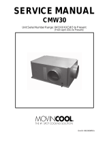
General Description
Major Components
Figure 1, Major Component Location
General Description
The centrifugal MicroTech ΙΙ control system consists of a microprocessor-based controller in the control
panel, as well as on-board the compressors, providing monitoring and control functions required for the
controlled, efficient operation of the chiller. The system consists of the following components:
• Operator Interface Touch Screen (OITS), one per unit-provides unit information and is the primary
setpoint input instrument. It has no control function.
• Unit Controller, controls unit functions and communicates with other auxiliaries. It is the secondary
location for setpoint input if, and only if, the OITS is inoperative.
• On-board compressor controller mounted on each compressor that monitors compressor operation and
controls bearing operation.
The operator can monitor all operating conditions by using the unit-mounted OITS. In addition to providing
all normal operating controls, the MicroTech II control system monitors equipment protection devices on the
unit and will take corrective action if the chiller is operating outside of its normal design conditions. If a fault
condition develops, the controller will shut a compressor, or the entire unit, down and activate an alarm
output. Important operating conditions at the time an alarm condition occurs are retained in the controller’s
memory to aid in troubleshooting and fault analysis.
The system is password protected and only allows access by authorized personnel. The operator must enter
the password into the touch screen (or one of the controller's keypad) before any setpoints can be altered.
Compressor #2
Compressor #1
Power Panel
(Front End Box)
Unit
Control
Panel
Operator
Interface
Panel
(OITS)
Electronic Expansion Valve
Condenser
Relief Valves
Behind Panel
Evaporator Relief
Valve, Behind Panel
Control Panel

OMM 1008-1 9
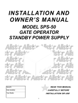
Control Panel
Figure 2, Control Panel
The unit controller, the OITS microprocessor, the unit and compressor on/off switches and other minor
components are mounted in the control panel. The switches are designated “I” for on and “0” for off. The
compressor on/off switch should only be used when an immediate stop is required since the normal shut
down sequence is bypassed.
The switch panel also has a circuit breaker that interrupts power to the cooling tower fans, valves, and
evaporator and condenser pumps, if any of these are tied into the MicroTech II controller for control of their
operation. If these components operate independently from the chiller control, the breaker has no effect.
The unit controller's function is acquiring and processing data relating to the chiller operation and issueing
instructions to various components to maintain controlled operation. The unit controller also sends
information to the OITS for graphic display. The controller has a 4x20 LCD display and keys for accessing
data and changing setpoints. If the OITS should become inoperable.The controller LCD can display most of
the same information as the OITS and can operate the chiller independently if the OITS is not available.
Emergency
Shutdown Switch,
Outside Panel
Terminal Board
TB UTB1 for Field
Wiring Connections
Controller
OITS PC
Universal
Communication
Module
Field Wiring Knockouts
On/Off
Switches
UNIT
COMP #1
COMP #2
Comp #2 I/O
Comp #1 I/O
EXV Board

10 OMM 1008-1
Use with On-Site Generators
Magnitude chillers have their total tonnage divided between two compressors (all but single compressor Model
WMC 145S) that start sequentially and they are operated with variable frequency drives. These features make
Magnitude chillers especially appropriate for use in applications where they may be required to run with on-site
electrical generators. This is particularly true when the generators are used for temporary power when the utility
power is lost.
Starting/Stopping Procedure: The stopping of the chiller in the event of a power failure is typically uneventful.
The chiller will sense a loss of voltage and the compressors will stop, coasting down using power generated
from their dynamic braking to maintain the bearing magnetic field. The stop signal will initiate a three-minute
stop-to-start timer, effectively preventing compressor restart for three minutes. The timer is adjustable from
three to fifteen minutes, but the recommended and default value is three minutes. This interval allows the
generator sufficient time to get up to speed and stabilize. The chiller will restart automatically when the start-to-
start timer expires.
Transfer Back to Grid Power: Proper transfer from stand-by generator power back to grid power is essential to
avoid compressor damage.
!
WARNING
Stop the chiller before transferring supply power from the generator back to the utility power grid.
Transferring power while the chiller is running can cause severe compressor damage.
The necessary procedure for reconnecting power from the generator back to the utility grid is show below.
These procedures are not peculiar to McQuay units only, but should be observed for any chiller manufacturer.
1. Set the generator to always run five minutes longer than the unit start-to-start timer, which could be set
from 15 to 60 minutes. The actual setting can be viewed on the operator interface panel on the
Setpoint/Timer screen.
2. Configure the transfer switch, provided with the generator, to automatically shut down the chiller before
transfer is made. The automatic shut-off function can be accomplished through a BAS interface or with
the “remote on/off” wiring connection shown in Figure 8 on page 29. A start signal can be given anytime
after the stop signal since the three-minute start-to-start timer will be in effect.
Chiller Control Power: For proper operation on standby power, the chiller control power must remain as
factory-wired from a unit-mounted transformer. Do not supply chiller control power from an external power
source because the chiller may not sense a loss of power and do a normal shutdown sequence.
Multi-Chiller Setup
Component Description
Communication Setup
The communication wiring and setup required for dual compressor operation is performed in the
factory and should be reviewed when the chiller is initially started after installation or if there is any
change made in the chiller control hardware.
RS485 communication wiring between chillers should be field wired before start-up and installed as
a NEC Class 1 wiring system.

OMM 1008-1 11
Table 1, pLAN address and DIP Switch Settings for Controllers Using pLAN.
Chiller
(1)
Comp 1
Controller
Comp 2
Controller
Unit
Controller
Reserved Operator
Interface (2)
Reserved
Dec. 1 2 5 6 7 8
A
Bin. 100000 010000 101000 011000 N/A 000100
Dec. 9 10 13 14 15 16
B
Bin. 100100 010100 101100 011100 N/A 000010
NOTES for pLAN multi-chiller communication setup:
1. Two Magnitude units can be interconnected.
2. Operator Interface Touch Screen (OITS) setting is not a DIP switch setting. The OITS address is selected by
selecting the ‘service’ set screen. Then, with the Technician level password active, select the ‘pLAN Comm’
button. Buttons A(7), B(15), C(23), D(31) will appear in the middle of the screen, then select the letters for
the OITS address for the chiller that it is on. Then close the screen. Note that A is the default setting from
the factory.
3. For the pCo2 controller, the pLAN address can be confirmed by viewing the DIP switch positions and
comparing to the table above (Bin. rows). There are six Binary DIP Switches: Up is ‘On’, indicated by ‘1’.
Down is ‘Off’, indicated by ‘0’. They are slide and not rocker switches.
4. For the pCo3 controller, there are no DIP switches as shown below.
The pLAN address can only be confirmed as follows:
A) Disconnect pLAN (connectors J10 and J11) from all pCo2 and pCo3 controller(s).
B) Cycle power to the controller and then hold down both the Left Arrow (alarm) and the Up Arrow keys simultaneously
as the controller completes its Self-Test routine. The controller will then show you the present pLAN address of
the controller. Verify that the pLAN address matches the desired address from the above table (Dec. rows). If the
address needs to be changed, follow the instructions displayed on the pCo3 controller’s LCD display. Press enter
when done.
C) Only after all controllers pLAN addresses have been set/confirmed can the pLAN network connectors be re-
connected.

12 OMM 1008-1
Operator Interface Touch Screen (OITS) Settings
Settings for any type of linked multiple compressor operation must be made to the MicroTech II controller.
Settings on a dual compressor unit are made in the factory prior to shipment, but must be verified in the field
before startup. Settings for multiple chiller installations are set in the field on the Operator Interface Touch
Screen as follows:
Maximum Compressors ON – SETPOINTS - MODES screen, Selection #10 = 2 for a WMC, 4 for 2 WMCs.
Sequence and Staging – SETPOINTS - MODES screen, Selection #11 & #13; #12 & #14. Sequence sets the
sequence in which compressors will start. Setting all to “1” evokes the automatic lead/lag feature and is the
preferred setting.
Nominal Capacity – SETPOINTS - MOTOR screen, Selection #10. The setting is the compressor design
tons. Compressors on dual units are always of equal capacity.
Communication Setup
1. With no communication connections between chillers, disconnect control power and set the pLan
address as shown in Table 1.
2. With all manual switches off, turn on control power to each chiller and set each OITS address (see
Note 2 above).
3. Verify correct nodes on each OITS Service Screen.
4. Connect chillers together (pLAN, RS485, between J6 connections on each unit’s isolation boards.
The boards are not furnished, separate RS485 isolators must be field supplied.
5. Verify correct nodes on each OITS Service Screen. See Figure 26 on page 50.
Operating Limits:
Maximum standby ambient temperature, 130°F (55°C)
Minimum operating ambient temperature (standard), 35°F (2°C)
Leaving chilled water temperature, 36°F to 60°F (2.2°C to 15°C)
Maximum operating evaporator inlet fluid temperature, 66°F (19°C)
Maximum startup evaporator inlet fluid temperature, 90°F (32°C)
Maximum non-operating inlet fluid temperature, 100°F (38°C)
Minimum condenser water entering temperature, 55°F (12.8°C)
Maximum condenser entering temperature, 105F (40.6C)
Maximum condenser leaving temperature, 115F (46.1C)

OMM 1008-1 13
Low Condenser Water Temperature Operation
When the ambient wet bulb temperature is lower than design, the entering condenser water temperature can
be allowed to fall to improve chiller performance. This is especially true of an advanced design such as the
McQuay Magnitude chiller that features variable compressor speed.
It is an engineering fact that as the compressor discharge pressure is reduced, the amount of power to pump
a given amount of gas also is reduced. The reduction can result in significant energy savings.
However, as with most centrifugal chiller applications, a tower bypass valve must be installed and must be
controlled by the chiller MicroTech II controller. Figure 3 illustrates two temperature actuated tower
bypass arrangements. The “Cold Weather” scheme provides better startup under cold ambient air
temperature conditions. The check valve may be required to prevent entraining air at the pump inlet.
Figure 3, Bypass, Mild Weather Operation
Bypass, Cold Weather Operation

14 OMM 1008-1
Operating the Control System
Interface Panel On/Off
The Operator Interface Panel is turned on and off with a switch located at the lower front of the panel.
Screen control buttons are located to either side of it and elicit on-screen prompts when pressed.
The screen is equipped with a screen saver that blackens the screen. Touching the screen anywhere
reactivates the screen. If the screen is black, touch it first to be sure it is on before using the ON/OFF botton.
Start/Stop Unit
There are four ways to start or stop the chiller. Three are shown below and selected in SETPOINT\
MODE\SP3; the fourth way is through panel-mounted switches:
1. Operator Interface Panel (LOCAL)
Home Screen 1 has AUTO and STOP buttons that are only active when the unit is in "LOCAL
CONTROL." This prevents the unit from being accidentally started or stopped when it is normally under
control from a remote switch or BAS. When these buttons are pressed, the unit will cycle through its
normal starting or stopping sequence.
2. Remote SWITCH
Selecting SWITCH in SP3 will put the unit under the control of a remote switch that must be wired into
the control panel (see Figure 8 on page 8).
3. BAS
BAS input is field-wired into a module that is factory-installed on the unit controller.
Control Panel Switches
The unit control panel, located adjacent to the Interface Panel, has switches inside the panel for stopping the
entire unit or individual compressors. When the UNIT switch is placed in the OFF position, the chiller will
shut down through the normal shutdown sequence whether one or two compressors are on.
The COMPRESSOR switches will immediately shut down the compressor without going through the
shutdown sequence when placed in the OFF position. It is equivalent to an emergency stop switch.
Change Setpoints
Setpoints are easily changed on the Operator Interface Touch Screen (OITS). A complete description of the
procedure begins on page 38. Setpoints can also be changed in the unit controller, but this is not
recommended except in an emergency when the OITS is unavailable.
Alarms
A red ALARM light in the lower middle of any OITS screen is illuminated if there is an alarm. If the optional
remote alarm is wired in, it too will be energized.
There are three types of alarms:
• Fault, equipment protection alarms that shut a unit or compressor off.
• Problem, limit alarms that limit compressor loading in response to an out-of-normal condition. If the
condition that caused a limit alarm is corrected, the alarm light will be cleared automatically.
• Warning, notification only, no action taken by controller.
Any type will light the ALARM light. Procedures for dealing with alarms are shown below:
1. Press the alarm light button. This will go directly to the ACTIVE ALARMS screen.
2. The alarm description (with date stamp) will be shown.

OMM 1008-1 15
3. Press the ACKNOWLEDGE button to recognize the alarm.
4. Correct the condition causing the alarm.
5. Press the CLEAR button to clear the alarm from the controller. If the fault condition is not fixed, the
alarm will continue to be on and the unit will not be able to be restarted.
Component Failure
Chiller Operation without the Operator Interface Panel
The Operator Interface Touch Screen communicates with the unit controller, displaying data and transmitting
touch screen inputs to the controllers. It does no actual controlling and the chiller can operate without it.
Should the Touch Screen become inoperable, no commands are necessary for continuing unit operation. All
normal inputs and outputs will remain functional. The unit controller can be used to view operational data, to
clear alarms and to change setpoints, if necessary.
Component Description
Operator Interface Touch Screen
The operator interface touch screen (OITS) is the primary
device for entering commands and entries into the control
system. (Settings can also be made directly into the unit
controller.) The OITS can also display controller data and
information on a series of graphic screens. A single OITS is
used per unit.
Selected information from the OITS panel can be down-
loaded via a USB port located in the unit control panel.
The OITS panel is mounted on a moveable arm to allow
placement in a convenient position for the operator.
There is a screen-saver programed into the system. The
screen is reactivated by touching it anywhere.
Controller Description
Hardware Structure
The controller is fitted with a microprocessor for running the control program. There are terminals for
connection to the controlled devices (for example: solenoid valves, tower fans, pumps). The program and
settings are saved permanently in FLASH memory, preventing data loss in the event of power failure without
requiring a back-up battery.
The controller connects to other control boards, the on-board compressor microprocessors and the OITS via a
local communications network. The controller can also have an optional module to provide communication
for a BAS using standard open protocols.

16 OMM 1008-1
Keypad
A 4-line by 20-character/line liquid crystal display and 6-button keypad is mounted on the controller. Its
layout is shown below.
Figure 4, Controller Keypad
Air Conditioning
ALARM
VIEW
SET
<
<
<
The four arrow keys (UP, DOWN, LEFT, RIGHT) have three modes of use:
• Scroll between data screens in the direction indicated by the arrows (default mode).
• Select a specific data screen in the menu matrix using dynamic labels on the right side of the display such
as ALARM, VIEW, etc (this mode is entered by pressing the MENU key). For ease of use, a pathway
connects the appropriate button to its respective label on the screen.
•
Change field values in setpoint programming mode according to the following table:
LEFT key = Default RIGHT key = Cancel
UP key = Increase (+) DOWN key = Decrease (-)
These four programming functions are indicated by one-character abbreviation on the right side of the
display. This programming mode is entered by pressing the ENTER key.
Getting Started
There are two basic procedures to learn in order to utilize the MicroTech II controller:
1. Navigating through the menu matrix to reach a desired menu screen, and knowing where a particular
screen is located.
2. Knowing what is contained in a menu screen and how to read that information, or how to change a
setpoint contained in the menu screen.
Navigating
The menus are arranged in a matrix of screens across a top horizontal row. Some of these top-level screens
have sub-screens located under them.
There are two ways to navigate through the menu matrix to reach a desired menu screen.
1) One is to scroll through the matrix from one screen to another using the four ARROW keys.
2) Another way is to use shortcuts to work through the matrix hierarchy. From any menu screen,
a) Pressing the MENU key will take you to the top level of the hierarchy. The display will show
ALARM, VIEW, and SET as shown in Figure 4. One of these choices can then be selected by
pressing the key connected to it via the pathway shown in the figure.
b) Depending on the top-level selected, a second level of screens will appear. For example, selecting
ALARM will go the next level of menus under ALARM (ALARM LOG or ACTIVE ALARM).
Selecting VIEW will go the next level of menus (VIEW COMPRESSOR STATUS, VIEW UNIT
STATUS, VIEW EVAPORATOR, or VIEW CONDENSER). Selecting SET will go to a series of
menus for looking at and changing setpoints.
ENTER Key with
Green Run Light
Behind
MENU Key
ARROW Keys (4)
Key-to-Screen Pathway
Red Alarm Light Behind

OMM 1008-1 17
c) After selecting this second level, the desired screen can be acquired using the arrow keys. A typical
final screen is shown below.
Pressing the MENU key from any menu screen will automatically return you to the MENU mode.
Figure 5, Typical Menu Display and Keypad Layout
Air Conditioning
VIEW UNIT STATUS
Unit = COOL
Compr. #1/#2=OFF/OFF
Evap Pump = RUN
Menu Screens
A hierarchical menu structure is used to access the various screens. Each menu screen can have one to four
lines of information. Optionally, the last menu selection can access one of a set of screens that can be
navigated with the UP/DOWN arrow keys (see the scrolled menu structure below). Menu selection is
initiated by pressing the MENU key, which changes the display from a data screen to a menu screen. Menu
selections are then made using the arrow keys according to labels on the right side of the display (the arrows
are ignored). When the last menu item is selected, the display changes to the selected data screen. An
example follows showing the selection of the “VIEW COMPRESSOR (n) screen. Suppose the initial screen
is:
ALARM LOG
(data)
(data)
(data)
< ALARM
< VIEW
< SET
<
VIEW < COMPRESSOR
< UNIT
< EVAPORATOR
< CONDENSER
VIEW COMP (n)
(screen n data)
(screen n data)
(screen n data)
.
MENU Key
ENTER Key
ARROW Keys
After pressing the MENU button, the top-level menu screen will
show:
After pressing the “VIEW” menu button, a menu screen will
show:
After pressing the “COMPRESSOR” menu button, the selected
data screen will show;
Where “n” is the number of the last viewed COMPRESSOR
screen. The arrow keys will automatically return to the
“scroll” mode at this time. Different compressor screens can
then be selected with the UP/DOWN arrow keys.

18 OMM 1008-1
Unit Controller
Table 2, Unit Controller, Analog Inputs
# Description Signal Source Range
1 Reset of Leaving Water Temperature 4-20 mA Current 0-(10 to 80°F)
2
Entering Evaporator Water
Temperature
NTC Thermistor (10k@25°C) -58 to 212°F
3
Entering Condenser Water
Temperature
NTC Thermistor (10k@25°C) -58 to 212°F
4 Leaving Condenser Water Temperature NTC Thermistor (10k@25°C) -58 to 212°F
5 Liquid Line Refrigerant Temperature NTC Thermistor (10k@25°C) -58 to 212°F
6 Demand Limit 4-20 mA Current 0-100 %RLA
7 Evaporator Water Flow 4 to 20 mA Current 0 to 10,000 gpm
8 Condenser Water Flow 4 to 20 mA Current 0 to 10,000 gpm
9 Refrigerant Leak Sensor 4 to 20 mA Current 0 to 100 ppm
10 Leaving Evaporator Water Temperature NTC Thermistor (10k@25°C) -58 to 212°F
Table 3, Unit Controller, Digital Inputs
# Description Signal Signal
1 Unit OFF Switch 0 VAC (Stop) 24 VAC (Auto)
2 Remote Start/Stop 0 VAC (Stop) 24 VAC (Start)
3 Not Used
4 Evaporator Water Flow Switch 0 VAC (No Flow) 24 VAC (Flow)
5 Condenser Water Flow Switch 0 VAC (No Flow) 24 VAC (Flow)
6 Manual Off 0 VAC (Off) 24 VAC (Auto)
7 Evaporator Water Flow Switch 0 VAC (No Flow) 24 VAC (Flow)
8 Condenser Water Flow Switch 0 VAC (No Flow) 24 VAC (Flow)
Table 4, Unit Controller, Digital Outputs
# Description Load Output OFF Output ON
1 Evaporator Water Pump #1 Pump Contactor Pump OFF Pump ON
2 Evaporator Water Pump #2 Pump Contactor Pump OFF Pump ON
3 Condenser Water Pump #1 Pump Contactor Pump OFF Pump ON
4 Condenser Water Pump #2 Pump Contactor Pump OFF Pump ON
5 Tower Fan #1 Fan Contactor Fan OFF Fan ON
6 Tower Fan #2 Fan Contactor Fan OFF Fan ON
7 Spare
8 Alarm Alarm Indicator Alarm OFF Alarm ON
9 Tower Fan #3 Fan Contactor Fan OFF Fan ON
10 Tower Fan #4 Fan Contactor Fan OFF Fan ON
11 Compressor Off Emer. Solenoid
Circuit Breaker
ON
Circuit Breaker
OFF
Table 5, Unit Controller, Analog Outputs
# Description Output Signal Range
1 Cooling Tower Bypass Valve Position 0 to 10 VDC 0 to 100% Open
2 Cooling Tower VFD Speed 0 to 10 VDC 0 to 100%
3 EXV signal to IB Valve Control Bd. 0 to 10 VDC 0 to 100%
4 Y3 Electronic Expansion Valve 0 to 10 VDC 0 to 100% Open
Unit Controller Setpoints
The following parameters are remembered during power off, are factory set to the Default value, and can be
adjusted to any value in the Range column.
The “Type” column defines whether the setpoint is part of a coordinated set of duplicate setpoints in different
controllers. There are three possibilities as given below:
N = Normal setpoint - Not copied from, or copied to, any other controller.
M = Master setpoint - Setpoint is copied to all controllers in the “Sent To” column.
S = Slave setpoint - Setpoint is a copy of the master setpoint (in the unit controller).

OMM 1008-1 19
At power-up the slave node checks if the master node is operational and if so, it sets its copy of the setpoint
equal to the master’s. Otherwise, the setpoint remains unchanged. During normal operation, any time the
master setpoint changes, the slave is updated as well.
The PW (password) column indicates the password that must be active in order to change the setpoint. Codes
are as follows:
O = Operator, M = Manager, T = Technician (not available through the 4x20 display/keypad).
The following table groups setpoints that relate to the entire unit operation and are stored in the unit
controller. All settings are made through the OITS
Table 6, Controller Setpoints
Description Default Range Type PW
Unit
Unit Enable OFF OFF, ON M O
Control Source KEYPAD
KEYPAD, BAS,
DIGITAL INPUT
N O
Display Units
°F/psi °F/psi, °C/kPa
N O
Language ENGLISH ENGLISH, (TBD) N O
BAS Protocol NONE
NONE, BACnet, LonWorks,
MODBUS, N2
N M
Motor Amps
Demand Limit OFF OFF, ON N O
Minimum Amps 40% 20 to 80% N T
Maximum Amps 100% 40 to 100% N T
Soft Load OFF OFF, ON D M
Begin Amp Limit 40% 20 to 100% N M
Soft Load Ramp 5 min 1 to 60 min D M
Maximum Rate
0.5 °F/min 0.1 to 5.0 °F/min
D M
Minimum Rate
0.1 °F/min 0.0 to 5.0 °F/min
D M
Staging
Mode Normal Normal, Efficiency, Pump, Standby N M
Sequence # 1 1,2, … (# of Compressors) N M
Maximum Compressors ON 16 1-16 G M
Stage Delta T 1.0 0.5-5.0 G M
Full Load 120 sec 30 to 300 sec N T
Absolute Capacity 100 Tons 0 to 9999 Tons D T
Leaving Water
Cool LWT
44. 0°F 36.0 to 60.0 °F
M O
Startup Delta T
3.0°F 0.0 to 10.0 °F
M O
Shutdown Delta T
3.0°F 0.0 to 3.0 °F
M O
LWT Reset Type NONE NONE, RETURN, 4-20mA N M
Max Reset Delta T
0.0°F 0.0 to 20.0 °F
N M
Start Reset Delta T
10. 0°F 0.0 to 20.0 °F
N M
Timers
Evap Recirculate 30 sec 15 sec to 5 min N M
Start-Start 40 min 15 to 60 min N M
Stop-Start 3 min 3 to 20 min N M
Source No Start
70 °F 50 to 100 °F
D T
Pumps
Evap Pump
Pump #1
Only
Pump #1 Only, Pump #2 Only, Auto
Lead, #1 Primary, #2 Primary
N M
Cond Pump
Pump #1
Only
Pump #1 Only, Pump #2 Only, Auto
Lead, #1 Primary, #2 Primary
N M
Cooling Tower
Tower Control None None, Temperature, Lift N M
Tower Stages 2 1 to 4 N M
Continued on next page

20 OMM 1008-1
Description Default Range Type PW
Stage Up Time 2 min 1 to 60 min N M
Stage Down Time 5 min 1 to 60 min N M
Stage Differential (Temp)
3.0 °F 1.0 to 10.0 °F
N M
Stage Differential (Lift) 6.0 psi 1.0 to 20.0 psi N M
Stage #1 On (Temp)
70 °F 40 to 120 °F
N M
Stage #2 On (Temp)
75 °F 40 to 120 °F
N M
Stage #3 On (Temp)
80 °F 40 to 120 °F
N M
Stage #4 On (Temp)
85 °F 40 to 120 °F
N M
Stage #1 On (Lift) 35 psi 10 to 130 psi N M
Stage #2 On (Lift) 45 psi 10 to 130 psi N M
Stage #3 On (Lift) 55 psi 10 to 130 psi N M
Stage #4 On (Lift) 65 psi 10 to 130 psi N M
Cooling Tower Valve / VFD
Valve/VFD Control None
None, Valve Setpoint, Valve Stage,
VFD Stage, Valve SP/VFD Stage
N M
Valve Setpoint (Temp)
65 °F 40 to 120 °F
N M
Valve Setpoint (Lift) 30 psi 10 to 130 psi N M
Valve Deadband (Temp)
2.0 °F 1.0 to 10.0 °F
N M
Valve Deadband (Lift) 4.0 psi 1.0 to 20.0 psi N M
Stage Down @ 20% 0 to 100% N M
Stage Up @ 80% 0 to 100% N M
Valve Control Range (Min) 10% 0 to 100% N M
Valve Control Range(Max) 90% 0 to 100% N M
Valve Type
NC
(To Tower)
NC, NO N M
Minimum Start Position 0% 0 to 100% N M
Minimum Position @
60 °F 0 to 100 °F
N M
Maximum Start Position 100% 0 to 100% N M
Maximum Position @
90 °F 0 to 100 °F
N M
Error Gain 25 10 to 99 N M
Slope Gain 25 10 to 99 N M
Alarms
Evaporator Freeze
34.0 °F -9.0 to 45.0 °F
D T
Condenser Freeze
34.0 °F -9.0 to 45.0 °F
D T
Low Evap Pressure 26 psi 10 to 45 psi D T
Low Evap Pressure-Inhibit 38 psi 20 to 45 psi D T
Low Evap Pressure-Unload 31 psi 20 to 45 psi D T
High Discharge Temperature-
Shutdown
190 °F 120 to 240 °F
N T
High Discharge Temperature-
Load
170 °F 120 to 240 °F
N T
High Condenser Pressure 140 psi 120 to 240 psi D T
Motor Current Threshold 10% 1 to 20% N T
Surge High Suction SH - Start
50 °F 25 to 90 °F
N T
Surge High Suction SH - Run
25 °F 5 to 45 °F
N T
Service
Vane Mode AUTO AUTO, MANUAL N T
Unload Timer 10 sec 10 to 240 sec N T
STOP Timer 1 sec 1 to 240 sec N T
These setpoints are normally viewed or changed on the OITS.
/