Page is loading ...

S70-401 IOM/AUG 2000
File: SERVICE MANUAL - Section 70
Replaces: S70-401 IOM/AUG 95
Dist: 3, 3a, 3b, 3c
OPERATION - MAINTENANCE
MICROPROCESSOR CONTROL PANEL
THIS MANUAL CONTAINS OPERATION AND MAINTENANCE
INSTRUCTIONS. READ THOROUGHLY. FAILURE TO FOLLOW
THESE INSTRUCTIONS COULD RESULT IN DAMAGE OR IM-
PROPER OPERATION OF THE UNIT.

RXF PLUS MICROPROCESSOR CONTROL PANELS70-401 IOM/AUG '00
Page 2
TABLE OF CONTENTS
TABLE OF CONTENTS
RXF PLUS MICROPROCESSOR CONTROL PANEL ............................................................ 4
KEYS AND KEY FUNCTIONS................................................................................................. 5
OPERATING DISPLAYS .......................................................................................................... 5
ANNUNCIATOR DISPLAY....................................................................................................... 6
SHUTDOWN DISPLAY ............................................................................................................ 9
SETPOINT DISPLAY ............................................................................................................... 9
SECURITY DISPLAY ............................................................................................................. 11
SETBACK DISPLAY .............................................................................................................. 12
AUTOCYCLE DISPLAY ......................................................................................................... 12
ANALOG OFFSET DISPLAY ................................................................................................. 12
COMMUNICATIONS DISPLAY .............................................................................................. 13
ADDITIONAL FEATURES...................................................................................................... 13
1 TO 4 STEP CONDENSER CONTROL ............................................................................... 13
3 LEAD LAG OPTION ............................................................................................................ 14
COMPRESSOR SEQUENCING............................................................................................ 15
TROUBLESHOOTING ........................................................................................................... 16
MICROPROCESSOR TELECOMMUNICATIONS ................................................................. 16
COMMUNICATIONS PROTOCOL......................................................................................... 16
SPECIFICATIONS..................................................................................................................16
TROUBLESHOOTING THE RXF PLUS MICROPROCESSOR............................................. 19
WIRING DIAGRAM ................................................................................................................ 22
SBC BOARD.......................................................................................................................... 26
P & I DIAGRAMS ................................................................................................................... 27
RECOMMENDED SPARE PARTS ........................................................................................ 33

RXF PLUS MICROPROCESSOR CONTROL PANEL S70-401 IOM/AUG '00
Page 3
PREFACE
This manual has been prepared to acquaint the owner and service person with the OPERATION and TROUBLESHOOTING
procedures as recommended by Frick Company for RXF PLUS Rotary Screw Compressor Units. It should be used in conjunc-
tion with the S70-400 IOM Manual.
OPERATION

RXF PLUS MICROPROCESSOR CONTROL PANELS70-401 IOM/AUG '00
Page 4
and remove all power from the outputs. This will shut down
the compressor motor and all control power (120v) to the
compressor auxiliary systems such as the oil pump and liq-
uid injection solenoid. THE EMERGENCY STOP BUTTON
IS FOR EMERGENCY SHUTDOWN SITUATIONS ONLY
and MUST NOT BE USED TO ROUTINELY SHUT OFF
THE COMPRESSOR.
The microprocessor hardware contains an internal watch-
dog circuit. If the microprocessor should fail, this circuit will
disable (turn off) all outputs.
The RXF compressor is controlled by a state-of-the-art mi-
croprocessor control system. The microprocessor continu-
ously monitors the compressor unit’s condition and opera-
tion. The microprocessor also directs instructions to the vari-
ous compressor unit subsystems.
The microprocessor has a membrane switch keyboard.
Pressing the keyboard in the area outlined as a key will cause
that function to be recognized by the microprocessor. The
keyboard has 32 membrane-type keys.
In addition to the keyboard, there is an emergency stop but-
ton. Pushing the emergency stop will bypass the computer
RXF PLUS MICROPROCESSOR CONTROL PANEL
OPERATION

RXF PLUS MICROPROCESSOR CONTROL PANEL S70-401 IOM/AUG '00
Page 5
KEYS AND KEY FUNCTIONS
The [CHANGE] key rotates the display through the differ-
ent display screens. The [CHANGE] key is also used to
change the status of various setpoints. This key, when
pressed, will cause the existing settings to be replaced with
“#” symbol for each number of the setting. To change from
pounds per square inch (G) to inches of mercury
(
Hg
)
, press
the [CHANGE] key when the (G) or
(
Hg
)
is flashing.
The [STEP] key steps or moves a set of flashing characters
through the Adjustable setpoints on the Setpoints displays,
the Auto-cycle displays, and the Security displays. The set-
point replaced by the flashing “#” symbol may be changed
or updated. The [STEP] key is also used to step through the
information displays when the Annunciator, Shutdown, or
Freeze displays are selected.
NOTE: The [ * ] key is used to step or move to previous
screens, described above, one at a time.
The [ENTER] key is used to change or enter new setpoints.
The [CLEAR] key will reset an alarm or cutout indication on
the annunciator screen(s) and will clear the microprocessor
to allow continued operation or restarting if all conditions
have returned to normal and no other control lockouts are
in force.
The [NUMERIC KEYPAD] is used to introduce new set-
point limits.
The [+/-] key will call up the Analog Offset display, page 1,
then page 2.
The [RUN], [STOP], and [REMOTE START] keys control
the starting and stopping of the compressor unit.
The [ALARM SILENCE] key will deenergize the alarm horn
output.
The [AUTO], [REMOTE], and [MANUAL] keys control the
operation of the compressor slide valve.
The [AUTO], [MANUAL 2.2], [MANUAL 3.5], and [MANUAL
5.0] keys control the operation of the compressor slide stop.
The [F1] function key will return the operator to the main
operating display. This function may be invoked at any time,
even during setpoint entry. While at the main display, press-
ing [F1] will jump directly to the annunciator if there are any
annunciated fails.
The [F2] function key will call up the Security display.
The [F3] function key will call up the first menu of the Set-
back feature.
The [F4] function key will call up the Auto Cycle display.
NOTE: To exit the Auto Cycle display, press the [F1] key
as prompted by the display.
The microprocessor has a liquid crystal display in a 2 line
by 20 character format, for a total of 40 characters. When
power is first applied to the control panel, the unit will be in
the Operating display mode. To change to a different dis-
play mode, press the [CHANGE] key. The display modes in
their order of rotation are:
1. Operating display (7 pages)
2. Annunciator display (43 possible pages)
3. Setpoints display (11 pages, 3 fixed Setpoint pages)
4. Communications display (1 page)
[F2] Security display (1 page)
[F3] Setback (3 pages)
[F4] Auto Cycle display (3 pages)
[+/-] Analog Offset display (4 pages)
OPERATION
OPERATING DISPLAYS
There are 7 operating displays which continuously update
and provide a variety of information in regard to the current
status of the compressor’s condition and performance.
OPERATING DISPLAY, Page 1*
SUCT. =///./g +///F
DISCH.=///G +///F
The information furnished by the Operating display is:
SUCT - Suction Pressure is measured at the compressor
inlet and is displayed in pounds per square inch gauge (G)
or in inches of mercury
(
Hg
)
.
DISCH - Discharge Pressure is measured at the compressor
outlet and is displayed in pounds per square inch gauge (G).
SUCT - Suction Temperature in degrees Fahrenheit is dis-
played. The shaded area will flash between cutout or alarm
if a fail exists. It will also flash between MLSL (Motor Load
Stop Load) or MLFU (Motor Load Force Unload) for motor
amps load control indication.
DISCH - Discharge Temperature in degrees Fahrenheit is
displayed.
OPERATING DISPLAY, Page 2*
COMP-mode DAY HH:MM
stat SS=/./ SV=///
COMP-mode - mode displays the start status of the com-
pressor unit. The mode of operation will be indicated as ei-
ther manual (MAN) when the [RUN] key has been pressed,
automatic (AUTO) when Auto Cycle has been activated, re-
mote (RMT) when the [RMT] key has been pressed, or off
(OFF MODE).
COMP-stat - stat displays the following messages: (OFF) not
running, (RNG) running, (MLFU) motor load control force un-
load, (MLSL) motor load control stop load, and (CUT) cutout.
SS - Slide Stop position is the position selected by the micro-
processor to provide the highest efficiency at any given suction
and discharge pressure condition.
SV - Slide valve position is displayed as a percentage. This
percentage reflects the mechanical position of the slide valve
and does not reflect the percentage of full-load operation.
* Display for illustrative purposes only.

RXF PLUS MICROPROCESSOR CONTROL PANELS70-401 IOM/AUG '00
Page 6
OPERATING DISPLAY, Page 3*
SUCT DISCH OIL
///./G /// ///
SUCT - Suction Pressure is measured at the compressor
inlet and is displayed in pounds per square inch gauge (G)
or in inches of mercury
(
Hg
)
.
DISCH - Discharge Pressure is measured at the compressor
outlet and is displayed in pounds per square inch gauge (G).
OIL - Oil Pressure is measured prior to entering the compres-
sor and is displayed in pounds per square inch gauge (G).
OPERATING DISPLAY, Page 4*
SUCT DISCH OIL SEP,
+///F ///F ///F ///F
SUCT - Suction Pressure is measured at the compressor
inlet and is displayed in pounds per square inch gauge (G)
or in inches of mercury
(
Hg
)
.
DISCH - Discharge Pressure is measured at the compressor
outlet and is displayed in pounds per square inch gauge (G).
OIL - Oil Temperature is displayed in degrees Fahrenheit.
SEPARATOR - Separator displays the oil separator tempera-
ture in degrees Fahrenheit.
OPERATING DISPLAY, Page 5*
FLA HEATER PUMP
///% off on
FLA - Percent Full-Load Amps displays the percentage of
the drive motor full-load amperage rating that the motor is
currently using.
HEATER - Heater displays the condition of the oil separator
heater(s), indicating ON or OFF.
PUMP - If unit has a pump, this will be displayed.
OPERATING DISPLAY, Page 6* +
SV=///% C.C.=///./G
AUTO-L SUCT.P=///./G
SV - Slide valve position is displayed as a percentage. This per-
centage reflects the mechanical position of the slide valve and
does not reflect the percentage of full-load operation. Immedi-
ately below this information, space has been provided to indi-
cate whether the S.V. % is in the automatic (AUTO), manual
(MAN), or remote (RMT) mode. The microprocessor will control
this function in the automatic mode. To the right of the mode
indicator, these messages may appear:
L (indicates Slide Valve loading)
U (indicates Slide Valve unloading)
C.C. -Actual Capacity Control setpoint or
S.B. - Actual Setback setpoint
SUCT.P - Current Suction Pressure
OPERATING DISPLAY, Page 7* +
SV=///% C.C.=+///./F
AUTO-L Temp=+///./F
SV - Slide valve position is displayed as a percentage. This per-
centage reflects the mechanical position of the slide valve and
does not reflect the percentage of full-load operation. Immedi-
ately below this information, space has been provided to indi-
cate whether the S.V. % is in the automatic (AUTO), manual
(MAN), or remote (RMT) mode. The microprocessor will control
this function in the automatic mode. To the right of the mode
indicator, these messages may appear:
L (indicates Slide Valve loading)
U (indicates Slide Valve unloading)
C.C. -Actual Capacity Control setpoint or
S.B. - Actual Setback setpoint
TEMP = Current Capacity Control Temperature.
OPERATING DISPLAY, Page 8*
SLIDE STOP - /./
AUTO recycle 30 min
SLIDE STOP - Slide Stop position is the position selected
by the microprocessor to provide the highest efficiency at
any given suction and discharge pressure condition. Im-
mediately below this, an information space has been pro-
vided to indicate whether V ratio is in the automatic (AUTO)
or the manual (MAN) mode.
RECYCLE - A Recycle Delay message indicates that the com-
pressor has started and has shut down within the time delay
setpoint period. The Recycle Delay will prevent the compressor
from starting until the delay time expires and is intended to pre-
vent damage to the compressor motor from successive restarts.
During Recycle Delay, the microprocessor will alternatively flash
“RECYCLE DELAY” and the remaining delay time in minutes.
The (RECYCLE . . .) message appears only when the compres-
sor is in the recycle mode.
NOTE: Consult Motor Manufacturer for the recom-
mended duration of the Recycle Delay.
CAUTION: If the [RUN] key is pushed while the unit is in
Recycle Delay, the compressor will start at the end of
the delay period.
ANNUNCIATOR DISPLAY
When a prealarm or cutout occurs, a flashing ALARM or
SHUTD (shutdown) indicator will appear in the upper right
hand corner of the “Operating Display, Page 1” and in the
lower left hand corner of “Operating Display, Page 2”. To
determine the fault, rotate to the Annunciator display by pres-
sing the [CHANGE] key or press [F5] for direct jump to an-
nunciator menu.
The Annunciator display will show all failures, individually. If
there is only one failure, the annunciator display will appear
as shown on the following “Annunciator Display”, pages.
When the system has failed for more than one condition,
(USE STEP) will appear in the upper right side of the dis-
OPERATION
+ Only Page 6 or 7 will be displayed, based on the operat-
ing mode as selected on Setpoints, Page 7.
* Display for illustrative purposes only.

RXF PLUS MICROPROCESSOR CONTROL PANEL S70-401 IOM/AUG '00
Page 7
play. The applicable failure displays will be individually ro-
tated through by pressing the [STEP] key. Continued press-
ing of the [STEP] key will result in the applicable failure dis-
plays repeating.
At this time the alarm will stop flashing. Pressing the [CLEAR]
key while at the Annunciator display will clear all alarms and/
or cutouts.
In order to restore the Annunciator display and resume nor-
mal operation, it will be necessary to go through the follow-
ing steps:
1. Correct the conditions causing the alarm.
2. Press the [ALARM SILENCE] key. (This action may pre-
cede correcting the conditions causing the alarm).
3. To clear or reset the Annunciator pages, press the
[CLEAR] key. This will also clear the ALARM, SHUTD, or
CUTOUT indicator from the Operating display.
4. Press [F1] to call up the Operating display. If the condi-
tions causing the alarm have not been corrected or a new
fault has occurred, the ALARM, SHUTD, or CUTOUT mes-
sage will appear.
NOTE: Use of the Emergency Stop Button may trip one
or more alarm setpoints.
5. After all failures have been corrected and the [CLEAR]
key has been pressed and if there are no failures, the An-
nunciator display will show (NO FAILURES).
ANNUNCIATOR DISPLAY, NO FAILURES*
ANNUNCIATOR
NO FAILURES
ANNUNCIATOR DISPLAY, 1 FAILURE*
ANNUNCIATOR
HIGH PRESS CUTOUT
ANNUNCIATOR DISPLAY,
MULTIPLE FAILURES*
ANNUNCIATOR USE STEP
HIGH PRESS ALARM
The remaining screens show additional
failure messages that may appear.
ANNUNCIATOR DISPLAY*
ANNUNCIATOR
LOW PRESS CUTOUT
ANNUNCIATOR DISPLAY*
ANNUNCIATOR USE STEP
LOW PRESS ALARM
* Display for illustrative purposes only.
OPERATION
ANNUNCIATOR DISPLAY*
ANNUNCIATOR
OIL PRESSURE CUTOUT
ANNUNCIATOR DISPLAY*
ANNUNCIATOR
OIL PRESS ALARM
ANNUNCIATOR DISPLAY*
ANNUNCIATOR
HI OIL TEMP CUTOUT
ANNUNCIATOR DISPLAY*
ANNUNCIATOR
HI OIL TEMP ALARM
ANNUNCIATOR DISPLAY*
ANNUNCIATOR
LO OIL TEMP CUTOUT
ANNUNCIATOR DISPLAY*
ANNUNCIATOR
LO OIL TEMP ALARM
ANNUNCIATOR DISPLAY*
ANNUNCIATOR
DISCH TEMP CUTOUT
ANNUNCIATOR DISPLAY*
ANNUNCIATOR
DISCH TEMP ALARM
ANNUNCIATOR DISPLAY*
ANNUNCIATOR
COMPRESSOR AUXILIARY
ANNUNCIATOR DISPLAY*
ANNUNCIATOR
PUMP AUXILIARY
ANNUNCIATOR DISPLAY*
ANNUNCIATOR
OIL LEVEL
ANNUNCIATOR DISPLAY*
ANNUNCIATOR
COMP DIFFERENTIAL

RXF PLUS MICROPROCESSOR CONTROL PANELS70-401 IOM/AUG '00
Page 8
ANNUNCIATOR DISPLAY*
ANNUNCIATOR
LOW TEMP CUTOUT
ANNUNCIATOR DISPLAY*
ANNUNCIATOR
LOW TEMP ALARM
ANNUNCIATOR DISPLAY*
ANNUNCIATOR
AUX #1 ALARM
ANNUNCIATOR DISPLAY*
ANNUNCIATOR
AUX #1 SHUTDOWN
ANNUNCIATOR DISPLAY*
ANNUNCIATOR
SUPERHEAT ALARM
ANNUNCIATOR DISPLAY*
ANNUNCIATOR
SUPERHEAT CUTOUT
ANNUNCIATOR DISPLAY*
ANNUNCIATOR
SEP COND ALARM
ANNUNCIATOR DISPLAY*
ANNUNCIATOR
SEP COND CUTOUT
ANNUNCIATOR DISPLAY*
ANNUNCIATOR
AUX #2 ALARM
ANNUNCIATOR DISPLAY*
ANNUNCIATOR
AUX #2 SHUTDOWN
ANNUNCIATOR DISPLAY*
ANNUNCIATOR
SENSOR LOW SEP TEMP
ANNUNCIATOR DISPLAY*
ANNUNCIATOR
SENSOR LO DISCH TEMP
ANNUNCIATOR DISPLAY*
ANNUNCIATOR
SENSOR HI DISCH TEMP
ANNUNCIATOR DISPLAY*
ANNUNCIATOR
SENSOR LOW OIL TEMP
ANNUNCIATOR DISPLAY*
ANNUNCIATOR
SENSOR HIGH OIL TEMP
ANNUNCIATOR DISPLAY*
ANNUNCIATOR
SENSOR LOW OIL PRESS
ANNUNCIATOR DISPLAY*
ANNUNCIATOR
SENSOR HI OIL PRESS
ANNUNCIATOR DISPLAY*
ANNUNCIATOR
SENSOR LO SUCT PRESS
ANNUNCIATOR DISPLAY*
ANNUNCIATOR
SENSOR LO DISCH PRES
ANNUNCIATOR DISPLAY*
ANNUNCIATOR
SENSOR HI DISCH PRES
ANNUNCIATOR DISPLAY*
ANNUNCIATOR
LOW MOTOR AMPS
ANNUNCIATOR DISPLAY*
ANNUNCIATOR
FACTORY DEFAULTS SET
* Display for illustrative purposes only.
OPERATION

RXF PLUS MICROPROCESSOR CONTROL PANEL S70-401 IOM/AUG '00
Page 9
LPCO - The Low Suction Pressure Cutout, reported in
pounds per square inch gauge (G) or inches of mercury
(
Hg
)
,
will shut down the compressor if the suction pressure drops
to this limit or lower, for 90 seconds or longer.
LPA - The Low Suction Pressure Alarm, reported in pounds
per square inch gauge (G) or inches of mercury (Hg), will
trigger a prealarm if the suction pressure drops to this limit
or lower.
SETPOINT DISPLAYS, Page 3*
TEMP CC LTCO+///./F
+///./F LTA +///./F
CC - The capacity control setpoint is for normal temperature
control operation, not setback.
CCSP - The Capacity Control Setpoint, reported in OF, con-
trols the loading and unloading of the compressor when S.V.
is in the automatic (AUTO) mode and press control mode is
selected.
LTCO - This setpoint will stop the compressor if the CC Tem-
perature drops below the setpoint. There is no time delay on
the temperature cutout.
LTA - An alarm will be activated if the CC Temperature drops
below the setpoint. There is no time delay on the tempera-
ture alarm.
SETPOINT DISPLAYS, Page 4*
PRESS PB DB CT
// /./ //
SETPOINT DISPLAYS, Page 5*
TEMP PB DB CT
// /./ //
Deadband - This setpoint is a + (plus) or - (minus) value
above or below the setpoint at which the compressor will
neither load or unload. A “Dead band” of 1 is the default
value. It is adjustable between .5 lb to 5.0 lb in increments of
.5. Use the [Step] key to select this setpoint then press the
[Change] key to toggle through the available selections.
Proportional Band - This setpoint is used to determine the
amount of time the load/unload solenoid is energized, ac-
cording to how far away from the setpoint the actual control
pressure is. The smaller the number the longer a load/un-
load signal will be sent. A “Prop. Band” of 10% is the default
value. It is adjustable to 2, 5, 10, 15, 20, or 25 percent. Use
the [Step] key to select this setpoint then press the [Change]
key to toggle through the available selections.
Cycle Time - The cycle time setpoint is the amount of time
between the beginning of each load/unload response. A
“Cycle Time” of 10 sec is the default value. It is adjustable to
5, 10, 15, 20, 25, or 30 seconds. Use the [Step] key to se-
lect this setpoint then press the [Change] key to toggle
through the available selections.
SHUTDOWN DISPLAYS, Top Page*
SHUTDOWN: USE STEP
KEY TO CHANGE PAGES
The Shutdown Record display keeps a record of the last six
shutdowns (cutouts). This information will help troubleshoot
persistent operational problems. When a cutout occurs, all
information is moved down one page and the new cutout
appears at the top of page 2. When the display is full, the
oldest record is dropped off the last display and is not re-
tained in memory. The information presented is echoed from
the Annunciator display, providing the type of cutout, the
day, the date, and the time. NOTE: This information will
not be lost due to power failure.
FREEZE DISPLAYS, Top Page*
FREEZE: USE STEP
KEY TO CHANGE PAGES
The Freeze display has the same appearance and contains
the same information as the Operating display. (For a de-
scription of the information presented by the Freeze display,
refer to the Operating display.) The Freeze display freezes
the information of the Operating display AT THE MOMENT
OF A COMPRESSOR CUTOUT. The information on the
Freeze display can help the operator to identify the cause of
a fault which occurred when no one was present. The Freeze
display will retain the information generated by a cutout un-
til a new cutout occurs or power is removed from the micro-
processor.
CAUTION: Do not confuse the Freeze display with the
Operating display. In order to avoid confusion remem-
ber that the displayed information on the Operating dis-
play is constantly being updated and changed. The
Freeze display is fixed.
NOTE: The Freeze display pages will appear as blank
screens when power is initially furnished to the unit, and
it will return to a blank screen anytime power is removed
from the microprocessor.
SETPOINT DISPLAYS, Page 1*
CAPACITY CONTROL
MODE = ///////////
MODE - This setpoint is used to select either Pressure Ca-
pacity Control or Temperature Capacity Control. NOTE: There
are only two setpoints, "PRESSURE" for pressure ca-
pacity control and "TEMPERATURE" for temperature ca-
pacity control.
SETPOINT DISPLAYS, Page 2*
PRESS CC LPCO=//./G
///./G LPA =//./G
CCSP - The Capacity Control Setpoint, reported in pounds per
square inch gauge (G) or inches of mercury (
Hg
), controls the
loading and unloading of the compressor when S.V. is in the
automatic (AUTO) mode and press control mode is selected.
OPERATION
* Display for illustrative purposes only.

RXF PLUS MICROPROCESSOR CONTROL PANELS70-401 IOM/AUG '00
Page 10
SETPOINT DISPLAYS, Page 6*
LO SUCT STOP LD//./G
LO SUCT F-UNLD //./G
They are active only while the compressor is operating in
Temperature Capacity Control Mode. The two new setpoints
are Low Suction Press Stop Load and Low Suction Press
Force Unload. Both are entered as a pressure in gauge or
inches of mercury
(
Hg
)
. When suction pressure reaches the
stop-load setpoint, loading of the compressor is inhibited.
When the suction reaches the force-unload setpoint, the
compressor will unload until the suction pressure is greater
than the force-unload setpoint. Control will then be released
to allow normal operation.
SETPOINT DISPLAYS, Page 7*
MLC STOP LOAD=/// %
MLC FORCE UNLOAD=/// %
MLC STOP LOAD - The Motor Load Control Stop Load,
reported as a percentage of the motor full-load amps (FLA),
will prevent the compressor capacity control from loading
when the setpoint is equaled or exceeded. NOTE: Consult
motor manufacturer for recommended setpoint.
MLC FORCE UNLD - The Motor Load Control Force Un-
load, reported as a percentage of the motor full-load amps
(FLA), will force the compressor to unload until the motor
full-load amps (FLA) fall within 1% of the setpoint or lower.
NOTE: Consult motor manufacturer for recommended
setpoint.
SETPOINT DISPLAYS, Page 8*
HPCO=///G AUX1-al-nc
HPA =///G AUX2-sh-no
HPCO - The High Discharge Pressure Cutout, reported in
pounds per square inch gauge (G), will shut down the com-
pressor if the discharge pressure equals or exceeds this
setpoint.
HPA - The High Discharge Pressure Alarm, reported in
pounds per square inch gauge (G) will trigger a prealarm if
the discharge pressure equals or exceeds this setpoint.
AUX 1 and AUX 2 - May be configured for either an alarm
(AL) or shutdown (SH) and with either a normally closed
(NC) or normally open (NO) contact.
SETPOINT DISPLAYS, Page 9*
Sup Heat-AL-10F-yes
Sep Cond-Sh-10F-yes
The setpoints provided on this display allow monitoring of
compressor superheat and condensing in the separator. The
following setpoints apply to the monitoring of the superheat
and condensing in the separator.
ALARM/(SHUTDOWN) - The Alarm(AL)/(shutdown)(SH)
setpoints select the conditions for an alarm or shutdown. If
alarm is selected, the alarm will occur after a 30 second
delay. If shutdown is selected, the shutdown will occur 60
seconds after the alarm.
OFFSET - This setpoint is the degrees F above the satura-
tion-point temperature where the alarm or shutdown will
occur.
ACT - The function selects whether the alarm/shutdown is
activated or not.
SETPOINT DISPLAYS, Page 10*
RECYCLE DELAY=// MIN
CT FACTOR =///
RECYCLE DELAY - The Recycle Delay displays the cur-
rent recycle delay setpoint in minutes. NOTE: Consult mo-
tor manufacturer for recommended setpoint.
CT FACTOR - The Current Transformer Factor records the
proper current transformer factor to match the compressor
motor FLA rating to the current transformer primary amp
rating. The CTF factor is programmable and its correct value
is determined by the following formula:
1024 x FLA (Full-Load Amps *)
CTF = 10 x CT (Current Transformer Primary Amps **)
* See motor nameplate.
** See CT located in starter panel.
EXAMPLE: FLA = 230 Amps
CT = 300 (300:5)
1024 x 230
CTF = = 80 (Round to whole number)
10 x 300
SETPOINT DISPLAYS, Page 11*
LOW % FLA = /// %
Low Motor Amp Failure - This addition to the program was
added for the purpose of detecting a broken coupling. If the
micro detects that the motor current is at 20% FLA or below
(adjustable setpoint) for 2 minutes, then a “Low Motor Amp
Cutout” will occur. The default for the setpoint is 20% with a
range from 0% to 100%. If a setpoint of 0% is entered, this
will disable this feature.
Low % FLA - The low % FLA setpoint is used to determine
if the coupling has broken. A “Low % FLA” setpoint of 20%
is the default value. It is adjustable from 0 to 100% FLA.
Use the [Step] key to select this setpoint then enter the
desired setpoint and press the [Enter] key.
SETPOINT DISPLAYS, Page 12*
HDTC=212 HOTC=167
HDTA=194 HOTA=159
HDTC - The High Discharge Temperature Cutout, reported
in degrees Fahrenheit, will shut down the compressor if the
discharge temperature equals or exceeds this setpoint.
HDTA - The High Discharge Temperature Alarm, reported
in degrees Fahrenheit, will shut down the compressor if the
oil temperature equals or exceeds this setpoint.
OPERATION
* Display for illustrative purposes only.

RXF PLUS MICROPROCESSOR CONTROL PANEL S70-401 IOM/AUG '00
Page 11
HOTC - The High Oil Temperature Cutout, reported in de-
grees Fahrenheit, will shut down the compressor if the oil
temperature equals or exceeds this setpoint.
HOTA - The High Oil Temperature Alarm, reported in de-
grees Fahrenheit, will trigger a prealarm if the oil tempera-
ture equals or exceeds this setpoint.
SETPOINT DISPLAYS, Page 13*
LOTC=49 HON=113
LOTA=58 HOFF=122
LOTC - The Low Oil Temperature Cutout, reported in de-
grees Fahrenheit, will shut down the compressor if the oil
temperature equals or falls below this setpoint.
LOTA - The Low Oil Temperature Alarm, reported in degrees
Fahrenheit, will trigger a prealarm if the oil temperature
equals or falls below this setpoint.
HON - The setpoint, in degrees Fahrenheit, to turn on the oil
heater when the oil temperature in the oil separator equals
or falls below this setpoint.
HOFF - The setpoint, in degrees Fahrenheit, to turn off the
oil heater when the oil temperature in the oil separator equals
this setpoint.
SETPOINT DISPLAYS, Page 14*
LOW OIL CUT = 030
LOW OIL ALARM = 025
No Pump version and Cycling Oil Pump version when pump
is not running. If the oil pressure is 25 pounds below the
discharge pressure or the oil pressure is within 10 pounds
of the suction pressure for 30 seconds, then the Alarm oc-
curs. If the oil pressure is 30 pounds below the discharge
pressure or the oil pressure is within 7 pounds of the suc-
tion pressure for 120 seconds and the Oil Pressure Alarm
has already been set, then the Cutout occurs.
Full-lube version and Cycling Oil Pump version when pump
is running. If the oil pressure is within 10 pounds of the dis-
charge pressure for 30 seconds then the Alarm occurs. If
the oil pressure is within 5 pounds of the discharge pres-
sure for 10 seconds and the Oil Pressure Alarm has already
been set then the Cutout occurs.
SETPOINT DISPLAYS, Page 15*
RXF-PLUS REV://////
NO PUMP/R717 mmddyy
This display shows the type and current revision of the program.
SETPOINT DISPLAYS, Page 16*
COM SETUP=FRICK STD
ID#=// BAUD=/////
ID - The ID number is a programmable identification code used
in telecommunications to access a specific compressor.
BAUD - Shows the baud rate of the RS-422 communication
port. Both ports are configured as follows: word = 8 bit, par-
ity = none or even, stop = 1 bit. The communications port is
programmable from 300 to 19200 baud.
SETPOINT DISPLAYS, Page 17*
DAY MMDDYY HH:MM:SS
/// ////// //://://
DATE - The Date displays the current date in the following
format: Month - Day - Year.
DAY - Day will display the current day of the week.
TIME - The Time displays the current time in the following
format: Hours - Minutes - Seconds. The time is in 24:00:00
hour clock format.
SECURITY DISPLAY*
KEYBD ENTRY enabled
enter code *****
The [F2] function key will call up the Security display. The
Security display allows the operator to either enable or dis-
able the microprocessor’s keyboard and, thereby, prevent
unauthorized tampering with the various adjustable setpoints.
When enabled, the microprocessor keyboard is fully opera-
tive and the security lockout is not in effect. When disabled,
the keyboard is rendered partially nonfunctional. All displays
will still be accessible through the keyboard. If any attempt
is made to enter new adjustable setpoints, however, the mi-
croprocessor will default to the Security display.
TO ENABLE THE KEYBOARD, press the [STEP] key so
that the brackets beside Enter Access Code flash; key the
proper five digit access code and press [ENTER]. The Set-
points Access will toggle from disabled to enabled and adjus-
table setpoint entry is now possible.
TO DISABLE THE KEYBOARD, press the [F2] function key
to call up the Security display; press the [STEP] key until the
brackets beside Enter Access Code flash; key the proper five
digit access code and press [ENTER]. Now press the [STEP]
key until the brackets beside Setpoints Access flash, and press
the [CHANGE] key to toggle from enabled to disabled.
TO CHANGE THE ACCESS CODE, press the [F2] function
key to call up the Security display; press the [STEP] key until
the brackets beside Enter Access Code flash; key the proper
five digit access code and press [ENTER]. Now, select the
Enter Access Code a second time by pressing the [STEP] key
until the brackets beside Setpoints Access flash; key in the new
five digit access code and press [ENTER].
NOTE: Power loss will not effect the Security display.
NOTE: IF NO ACCESS CODE WAS ENTERED AND THE
DISABLED COMMAND WAS SELECTED, THE ACCESS
CODE IS [00000].
LOST OR FORGOTTEN ACCESS CODE: Consult Frick
Company for assistance.
OPERATION
* Display for illustrative purposes only.

RXF PLUS MICROPROCESSOR CONTROL PANELS70-401 IOM/AUG '00
Page 12
(Start) TIMER - This is a time delay used to start the com-
pressor. The timer only accumulates time whenever the pres-
sure rises to or above the “START” setpoint and will reset if
the pressure drops below the “START” setpoint.
STOP - The suction pressure must be less than or equal to
the displayed “STOP” setpoint limit in order to stop the com-
pressor. This setpoint works in conjunction with the “TIMER”
setpoint located to the right of it on the display. NOTE: This
limit must be set higher than Low Suction Pressure Cut-
out and the Low Suction Pressure Alarm setpoints.
(Stop) TIMER - The (stop) TIMER is a time delay used to
stop the compressor. The timer only accumulates time when-
ever the pressure drops to or below the “STOP”.
AUTOCYCLE DISPLAY, Page 3*
START=+//./F // MIN.
STOP =+//./F // MIN.
The Auto Cycle display provides for independently adjustable
setpoints to turn the compressor on and off in response to the
suction temperature or as an adjustable setpoint to limit the
minimum slide valve position. The compressor can be started
and stopped by the following temperature setpoints, even if
the capacity control is selected to pressure.
START - The CC (capacity control) Temperature must be
greater than or equal to the “START” setpoint in order to
start the compressor. This setpoint works in conjunction with
the “TIMER” setpoint located to the right of it on the display.
(Start) TIMER - This is a time delay used to start the com-
pressor. The timer only accumulates time whenever the CC
Temperature rises to or above the “START” setpoint and will
reset if the CC Temperature drops below the “START”
setpoint.
STOP - The CC Temperature must be less than or equal to
the “STOP” setpoint in order to stop the compressor. This
setpoint works in conjunction with the “TIMER” setpoint lo-
cated to the right of it on the display.
(Stop) TIMER - The (stop) TIMER is a time delay used to
stop the compressor. The timer only accumulates time when-
ever the CC Temperature drops to or below the “STOP”
setpoint and will reset if the CC Temperature rises above
the “STOP” setpoint.
ANALOG OFFSET DISPLAY, Page 1*
SUCTION DISCH OIL PRESS
+/./ +/ +/ ///./g
ANALOG OFFSET DISPLAY, Page 2*
FILT ECON PRESS
+/ +/ ///./g
ANALOG OFFSET DISPLAY, Page 3*
DISCH OIL SEP TEMP
+/ +/ +/ ///./g
* Display for illustrative purposes only.
SETBACK DISPLAY, Page 1*
SETBACK ACTIVE = ///
The [F3] function key will call up the Setback display. The
Setback feature enables automatic operation at two sepa-
rate suction conditions on a preset time schedule. Having
entered the desired Setback setpoint, enter the start and
stop time or times and select Active: (Yes) or (No).
SETBACK DISPLAY, Page 2*
SETBACK PRESS= ///./G
SETBACK TEMP=+//./F
SETBACK PRESS - The capacity-control setpoint is used
when in the Setback mode and Pressure is selected as the
capacity control desired.
SETBACK TEMP - The capacity-control setpoint is used
when in the Setback mode and Temperature is selected as
the capacity control desired.
SETBACK DISPLAY, Page 3*
SETBACK START=//.//
DAY=/// STOP =//.//
AUTOCYCLE DISPLAY, Page 1*
AUTOCYCLE MIN.SV=//%
ENABLE=pres
MIN. SV - Minimum Slide Valve Position, shown as a per-
centage, will limit the slide valve position to the displayed
setpoint.
ENABLE - Indicates whether Auto Cycle is active (YES) or
not active (NO). Press the [CHANGE] key while at this
setpoint to change the status. Upon deactivation, the com-
pressor will return to the previous mode of operation.
The Analog Offset Display is accessed by pressing [+/-] key.
AUTOCYCLE DISPLAY, Page 2*
START=///./G // MIN.
STOP=///./G // MIN.
The Auto Cycle Pressure Control Display is accessed by
pressing the [F4] key.
The Auto Cycle display provides for independently adjus-
table setpoints to turn the compressor on and off in response
to the suction pressure or as an adjustable setpoint to limit
the minimum slide valve position. The compressor can be
started and stopped by the following pressure setpoints even
if the capacity control is selected to temperature.
START - The suction pressure must be greater than or equal
to the “START” setpoint in order to start the compressor.
This setpoint works in conjunction with the “TIMER” setpoint
located to the right of it on the display.
OPERATION

RXF PLUS MICROPROCESSOR CONTROL PANEL S70-401 IOM/AUG '00
Page 13
ANALOG OFFSET DISPLAY, Page 4*
SUCT SPARE TEMP
+/ +/./ ///./F
DISCH OIL SEP TEMP
+0 +0 +2
All analog values can be offset + or - 5 units, depending on
which value is being adjusted. Use the [STEP] key to step
through the desired setpoint. Press the [CHANGE] key to
change the value of the offset by 1. The actual analog value
will be displayed under the word “PRESS” or “TEMP”.
COMMUNICATIONS DISPLAY*
COM IN:
## OUT:
COM IN - Displays character which the microprocessor has
received in the RS-422 communications port.
COM OUT - Displays the first 12 characters of information
which the microprocessor has transmitted out the RS-422
communications port.
## - Displays the number of characters the microprocessor
has received after a "#" character.
ADDITIONAL FEATURES
Compressor Differential Cutout - If the compressor runs for
5 consecutive minutes with a suction to discharge pressure
differential of 25 pounds or less, then the “Comp Differen-
tial” cutout occurs. The ability to run the compressor at a low
differential pressure required the following changes to en-
sure oil flow at the main oil injection port.
a. The compressor will force unloaded to 50% slide valve
and display an “F Unload” message when the following
condition is true:
((suction pressure (PSIA) x 1.5) + 10) - 14.7 >= Oil
Pressure and slide valve >50%
b. The compressor will be prohibited from loading and
display a “Ld Inhib” message while the following condi-
tion is true:
((suction pressure (PSIA) x 1.5) + 15) - 14.7 >= Oil
Pressure
Sensor Fault Failure - A “Sensor Fault” cutout was added
to the program to stop the compressor if a temperature or
pressure sensor is determined to be at it’s minimum or maxi-
mum limit for 5 seconds. The following channels and condi-
tions can cause this cutout:
Channel 2 - Low or High Discharge Temp (32 or 212OF)
Channel 3 - Low or High Oil Temp (0 or 180OF)
Channel 4 - Low Separator Temp (0OF)
Channel 6 - Low or High Oil Pressure (<0g or 285g)
Channel 8 - Low or High Discharge Pressure (<0g or
285g)
Channel 9 - Low Suction Pressure (29
Hg
only)
Pulse Load at 100% slide valve position - A new feature
has been added which will stop loading the compressor at
the normal rate when 100% slide valve is displayed. The
load signal will then be pulsed for 2 seconds every minute
when the slide valve is displaying 100% and the pressure is
above the setpoint.
1 TO 4 STEP CONDENSER CONTROL
The following information pertains to the RXF PLUS micro
with the condenser control feature option. The SETBACK
feature is removed to allow for the addition of the condenser
control programming. Pressing [F3] will take the operator
directly to the condensers main operating status menu. The
condenser feature uses three menus.
CONDENSER PRES /// G
1-ON 2OFF 3OFF 4OFF
Main condenser status menu, first page.
ON /// DELAY /// SEC
OFF /// LEAD STEP 1
Condenser menu, second page.
ACTIVE WHEN RUNNING
ACTIVE STEPS 1-3
Condenser menu, third page.
The first condenser page displays the current discharge pres-
sure and the current output status of up to four possible
steps of condenser control. This menu displays status only
and does NOT have any programmable setpoints.
Page 2 has four setpoints:
ON 160 DELAY 030 SEC
OFF 150 LEAD STEP 1
This represents the setpoint at which the micro will sequence
on additional steps of condenser capacity.
ON 160 DELAY 030 SEC
OFF 150 LEAD STEP 1
This represents the setpoint at which the micro will sequence
off steps of condenser capacity.
ON 160 DELAY 030 SEC
OFF 150 LEAD STEP 1
This represents the setpoint which determines the time de-
lay to sequence steps of condenser capacity.
ON 160 DELAY 030 SEC
OFF 150 LEAD STEP 1
This setpoint allows the operator to program a given step as
the LEAD step.
Page 3 has two setpoints:
ACTIVE WHEN RUNNING
ACTIVE STEPS 1-3
This setpoint has three possible settings that determine when
the condenser control feature is active. They are: "ACTIVE
RUNNING", "ALWAYS", and "NEVER".
OPERATION

RXF PLUS MICROPROCESSOR CONTROL PANELS70-401 IOM/AUG '00
Page 14
ACTIVE WHEN RUNNING
ACTIVE STEPS 1-3
This setpoint allows the operator to select how many steps
of condenser is required to be sequenced by the condenser
control feature.
NOTE: Operator may select more steps that are avail-
able. (Supported by hardware)
3 LEAD LAG OPTION
Before operating the equipment, the operator must review
this entire section. Both hardware and software must be
installed accordingly, to ensure proper operation.
There are 3 primary areas that must be considered:
1. Eprom chips
2. Hardware wiring
3. Master Control Settings
Lead Lag capable chips sets are identified by the LL option
designation. For example, a standard set of lead lag chips
would have the following printed on its label:
ORDER#
RXF-LL (a standard nonlead lag set would show
just RXF)
DATE U4 (U# indicates eprom chip socket location)
or U5
In a group, at least one RXF Plus must have a 3 lead lag set
of eproms installed. Further, the RXF Plus acting as the
sequence controller must have its communication cabling
wired according to the diagram under section “Wiring Dia-
grams”. While it is possible to use lead lag chips on all RXF
Plus compressors, it is best to use standard chips on the
OTHER compressors. Incorporating a complete program-
mable sequencing control program into the RXF Plus chip
set necessitated removing features such as Setback and
Auto-Cycle. Using standard chips on the other compres-
sors allows those compressors to switch to their Auto-Cycle
mode of operation automatically should communications
be lost. All lead lag based control is via the controlling RXF
Plus. Consult Section “Description of Menus and Their Set-
points” for definitions on the various setpoints regarding
lead lag operation.
Description of Menus and Their Setpoints
The following menus have been added:
NOTE ! The operator may gain access to these menus
by pressing the [CHANGE] key until the desired menu is
reached or by pressing the Function key [F3] and then
pressing the [change] or [ * ] keys to move forward or
backward through the available displays.
LEAD LAG STATUS # 1
IS NOT LL SELECTED
# _ Represents compressor 1, 2, or 3. )
The shaded area may show the following:
OFF IN RMT START ( Off in remote start. )
OFF IN MAN START ( Off in manual start. )
OFF IN A/C START ( Off in Auto-Cycle mode. )
OFF ANTI-RECYCLE ( Off with Recycle delay time
remaining. )
CUTOUT OR FAILED ( Compressor is off due to a
shutdown. )
RUNNING RMT START (Running in remote start.)
RUNNING MAN START (Running in manual start.)
RUNNING A/C START (Running in Auto-Cycle mode.)
NOT COMMUNICATING ( While selected to operate in
LL this compressor is not communicating. )
NOT IN RMT START (Compressor is not available to
start remotely.)
S.V. NOT IN REM. (Compressor Capacity Control is not
in Remote.)
NOT LL SELECTED (Compressor has not been se-
lected to operate in lead lag sequence.)
LEAD LAG CONTROL
MODE = PRESSURE
This menu allows the operator to enable the lead lag con-
trol to operate by either temperature or pressure capacity
control. Selecting DISABLED will turn the lead lag control
feature OFF.
NOTE: Lead lag capacity control uses the pressure and
temperature settings as entered on the controlling RXF
Plus.
Displayable modes (in shaded area of display above) are:
PRESSURE
TEMPERATURE
DISABLED
START 085.3G 060 SEC
STOP 029.9 hg 060 SEC
This menu allows the operator to enter a start and stop PRES-
SURE setpoint with a respective programmable time delay.
START +99.9F 060 SEC
STOP -51.0F 060 SEC
This menu allows the operator to enter a start and stop
TEMPERATURE setpoint with a respective programmable
time delay.
Definition of Start Stop Sec. Terms:
START - The “Comp Start” setpoint is the differential pres-
sure or temperature above setpoint that must be equaled
or exceeded in order to bring another compressor on line.
This setpoint works in conjunction with the “Start Delay”
setpoint.
OPERATION

RXF PLUS MICROPROCESSOR CONTROL PANEL S70-401 IOM/AUG '00
Page 15
START DELAY IN SECONDS -This is a common time delay
used between each step in the load sequence to ensure
that the need to add an additional compressor is justified.
This will preventa compressor starting due to momentary
load surges. The timer only accumulates time whenever
the deadband is equaled or exceeded, and resets any time
the pressure or temperature falls below the “Start” setpoint.
STOP - The “Comp Stop” setpoint is the differential pressure
or temperature below the setpoint that must be equaled or
exceeded before a compressor is taken off line. This setpoint
works in conjunction with the “Stop Delay” setpoint.
STOP DELAY IN SECONDS - This is a common time delay
used between each step in the unload sequence to ensure
that the need to stop a compressor is justified. This will
prevent the stopping of a compressor in response to a mo-
mentary load dip and subsequently needing to restart it in
a short period of time. The timer only accumulates time
whenever the pressure or temperature is equal to or below
the “Stop” setpoint, and resets any time the suction pres-
sure rises to within the “Stop” deadband.
MINIMUM SLIDE VALVE
COMP. #1 = 50 % SV
From this menu the operator may enter a minimum slide
valve setpoint for each compressor.
SEQUENCE SELECTION
COMP. #1 USES ID=01
This menu determines what compressors are to operate as
the #1=LEAD, #2=INTERMEDIATE and #3=LAG. A unique
ID code must be entered into the control panel of each
compressor. The ID codes do not have to be in any particu-
lar sequence. However, for simplicity’s sake, it is usually
best to use the ID codes 01 for the lead compressor, 02 in
the intermediate, and 03 in the lag compressor. So, from
this menu the compressor #1 entry should show ID=01,
compressor #2’s entry should show ID=02, and compres-
sor #3 should show ID=03.
NOTE: to change compressor sequence, the operator
must change either the ID codes on each compressor or
a better method would be to simply change the desig-
nated ID’s from this menu. Entering 00 will disable or
remove a given control ID code.
Example: compressor #1 running, compressor #2 ID’d to
00, and compressor #3 off. Should the sequence require
another compressor to come on line, then #2 would be
skipped and #3 would be started.
Notes:
a.Compressor designated as #1 is always LEAD. Com-
pressor designated as #2 is always the INTERMEDIATE.
Compressor designated as #3 is always LAG.
b. For the compressor to be controlled it must be in RE-
MOTE start and have its capacity control selected to re-
mote.
c.If the machine is failed, cutout, not in remote, or not lead
lag selected, then the compressor will not be controlled.
d. Any compressor below its minimum slide valve position
will be loaded for one second each minute to ensure that
they are within 5% of their minimum slide valve position.
If a compressor were allowed to unload further, it would
not allow proper load balance and correct compressor
sequencing would be difficult.
COMPRESSOR SEQUENCING
NOTE: The following references to pressure also apply
to temperature since this is a temperature/pressure ca-
pable system.
On system start-up, as the high-stage pressure exceeds
the Start setpoint for the Start Time Delay period, compres-
sor #1 will come on line and modulate in response to pres-
sure.
With #1 running:
If the load falls - #1 will unload to #1 Min SV setpoint. If the
suction pressure drops below the Stop setpoint for the Stop
Time Delay period, then #1 will turn off.
If the load rises - #1 will load up in response to pressure. If
the Start setpoint is exceeded for the Start time delay pe-
riod, then #2 will start.
With #1 and #2 running:
If the load falls - #2 will unload first to the #2 min. SV set-
point, then #1 will unload to its #1 min. SV setpoint. If the
pressure drops below the Stop setpoint for the Stop time
delay period, then #2 will stop.
If the load rises - #1 and #2 will load up in response to
pressure. If the Start setpoint is exceeded for the Start time
delay period, then #3 will start.
With #1, #2, and #3 running:
If the load falls - #1 will remain fully loaded, #3 will unload
to the #3 min. SV setpoint, then #2 will unload to the #2 min.
SV setpoint. If the pressure drops below the Stop setpoint
for the Stop time delay period, then #3 will stop.
If the load rises - #1 will remain fully loaded, #2 and #3 will
load up in response to pressure.
Differences between the RXF Plus 3 Lead
Lag Program and the Standard RXF Plus
Control Program
As was mentioned in the beginning of the 3 Lead Lag sec-
tion, there are several differences between the lead lag
and the standard version of the RXF Plus control programs.
With the addition of the lead lag feature, the Setback fea-
ture was removed. Pressing the [F3] key will jump you di-
rectly to the lead lag control menus. It was also necessary to
remove the Auto-Cycle feature. Pressing the [F4] key will
show an appropriate message indicating this.
When using the lead lag program but not enabling the lead
lag feature, a minimal communications capability was re-
tained. The Information request command, the start and stop
commands, and the motor amps request commands were
left in the program. These commands are needed in situa-
tions where all program EPROM’s are of the lead lag ver-
sion. All other commands were removed.
OPERATION

RXF PLUS MICROPROCESSOR CONTROL PANELS70-401 IOM/AUG '00
Page 16
through all menus, entering setpoints as required for the
system. Note that on initial power-up or simply on a loss of
setpoints the micro will display a NEW annunciation mes-
sage “FACTORY DEFAULTS SET”. If you need assistance
in optimizing setpoints, contact the FRICK Service Dept.
Since the lead lag version does not incorporate Auto-Cycle, it is
best to use standard programs on the compressors that the RXF
Plus controller sequences. This allows those compressors to au-
tomatically switch to their respective Auto-Cycle modes upon a 5
minute period of communications loss.
TROUBLESHOOTING
Most problems encountered with lead lag controls concern
two main areas:
1. Communications problems
2. Optimizing control sequencing
The RXF Plus lead lag control program has a new feature
that can be used to help diagnose communications prob-
lems. This feature may be accessed on a new display by
pressing the [F1] key, then pressing the [ * ] key once. This
new menu is actually the last menu in the program.
COM.IN:
## OUT:
The period after the word COM will blink for each character
received. While this may not be much help during normal
data exchanges, it will help the operator notice when the
micro is receiving abnormal single character hits. The ##
shows actual number of characters received since the last
pound # code was encountered, which will also reset this
counter to zero. Should the micro not receive a valid com-
mand sequence (most commands are less than 14 charac-
ters long) starting with a pound character, this counter will
count excessively high, up to 99 and stop, only resetting
upon receiving a pound code. The shaded area to the right
of IN: will show actual reception of data flow from right to left.
This information should be the normal data responses from
the compressors that the RXF Plus lead lag controller is
requesting data from. The shaded area to the right of OUT:
displays the actual command that the RXF Plus lead lag
controller is sending. This does not represent a feedback
loop verifying actual data sent; it only verifies what the mi-
cro is attempting to send.
The RXF Plus lead lag program has additional communi-
cations failure annunciation which will, on communication
failure to a given compressor, report a message such as
“COMP. #1 COMM. FAIL”, with its associated time of failure.
This feature is enabled once a nonzero ID code is entered
to add a compressor to the lead lag sequence and lead lag
is enabled. The controller must get 3 successive communi-
cations failures to actually set the failure, which also will
turn on the RXF Plus controllers alarm output. Individual
(single hit) communications errors will actually display “NOT
COMMUNICATING” in the LEAD LAG STATUS display. This
message will disappear once normal communications have
resumed.
Optimizing control sequence is combining an educated
guess with trial and error. Every system is to some degree
unique, either due to operating conditions, equipment cali-
bration, or simply the operators desired control. The RXF
Plus lead lag program, on initial power-up, defaults all set-
points to known values, such as all minimum slide valve
settings will default to 50 %. Start / Stop setpoints are actu-
ally defaulted to values that will prevent actual sequencing
from occurring. Hence the need for an operator to work
1 1/2" REF
13/4"
33/8"
1" REF
53/4"
3 5/8"
D
A
E
F
C
B
H
G
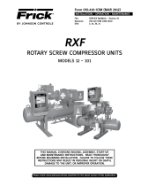
OUTLET
INLET
OUTLET
INLET
SRVSHNK1
MICROPROCESSOR
TELECOMMUNICATIONS
The Frick RXF Microprocessor comes with an onboard tele-
communications interface. The telecommunications feature
permits interfacing the microprocessor with a modem, re-
mote data communications terminal, or master computer
via RS-422 protocol. In the case of a modem, telephone
lines are used for the actual transmission of data permitting
communications from a remote location.
The components necessary to utilize the telecommunica-
tions feature will vary with the application. Information
concerning these items may be obtained from Frick Com-
pany, Waynesboro, Pa.
COMMUNICATIONS PROTOCOL
SPECIFICATIONS:
All commands must be in ASCII (CAPS) to be recognized. A
compressor with an ID code of [00] is considered disabled.
ID Codes from [01] thru [99] are valid and are recognized by
the microprocessor.
The following is a complete list of available command types:
COMMAND CODE and DESCRIPTION
I = Returns compressor status information.
R = Compressor start command.
S = Compressor stop command.
V = Compressor capacity control command.
P = Return Pressures information.
T = Return Temperatures information.
A = Return full load amps information.
C = Enter Change setpoints mode.
OPERATION

RXF PLUS MICROPROCESSOR CONTROL PANEL S70-401 IOM/AUG '00
Page 17
The following is a detailed description of each command:
RETURN COMPRESSOR STATUS INFORMATION: #IDI
# Start of command sequence.
ID Compressor ID code.
I Return Status information command.
RETURNED ANSWER, ie: 090RRRN340
Character Description
Position of returned data
1,2,3 Capacity control position.
4 Remote, Auto, Manual (Cap control)
5 Delay-recycle, Running, Off.
6 Rem, Man, Off, Auto (Compressor mode)
7 Cutout, Alarm, Normal.
8,9,10 Suction in PSIA.
(Carriage return, line feed.)
COMPRESSOR STOP COMMAND: #IDSID
# Start command sequence.
ID Compressor ID code.
S Stop compressor command.
ID ID code repeated for verification
NOTE: The compressor must be in the remote
start mode for this command to be executed.
RETURNED ANSWER: A01
Character Description
Position of returned data
1 Acknowledge of command sent.
2,3 ID code of compressor.
(Carriage return, line feed.)
COMPRESSOR SLIDE VALVE #IDVLXX
CONTROL COMMANDS: #IDVUXX
#IDVS
#IDVP
# Start command sequence.
ID Compressor ID code.
V Compressor control command.
L Load Slide valve command.
U Unload slide valve command.
XX = 00 Turns selected output off.
XX = 01 to 15 Turns selected output on
for XX seconds.
XX = 99 Turns selected output on.
S Return slide valve position value.
P Return slide stop position value.
If the command was #01VL00, then the load
slide valve output on compressor #1 would be
turned off. If the command was #01VL05, then
the load slide valve output on compressor #1
would be turned on for 5 seconds, and would
then automatically turn off. NOTE: the slide
valve must be in the remote mode for this
command to be executed.
RETURNED ANSWER (for L or U commands): AID
Character Description
Position of returned data
1 Acknowledge of command sent.
2,3 ID code of compressor.
(Carriage return, line feed.)
RETURNED ANSWER (for S command), ie: 090
1,2,3 Slide valve position.
RETURNED ANSWER (for P command), ie: 2.2
(Carriage return, line feed)
RETURN PRESSURES COMMAND: #IDPX
# Start command sequence.
ID Compressor ID code.
P Return pressures command.
X = S Return suction pressure (PSIA).
X = D Return discharge pressure (g/hg).
X = O Return oil pressure (g).
X = A Return all pressures.
If the command was #01PS, then the micro-
processor would dump the suction pressure.
RETURNED ANSWER:
XXX = 3 characters followed by a carriage
return, line feed.
If using the “A” command, then the returned
data would be:
XXXXXXXXXXXX = 12 characters followed by a
carriage return, line feed.
RETURN TEMPERATURES COMMAND: #IDTX
# Start command sequence.
ID Compressor ID code.
T Return temperature command.
X = D Return discharge temperature.
X = O Return oil temperature.
X = P Return separator temperature.
X = A Return all temperatures as a string
of data.
If the command was #01TS, then the micro-
processor would dump the suction temperature.
RETURNED ANSWER:
XXXX = 4 characters followed by a carriage
return, line feed for suction.
XXX = 3 characters followed by a carriage
return, line feed for discharge, oil,
and separator.
If using the “A” command, then the returned
data would be:
XXXXXXXXXXXXX = 13 characters followed by
carriage return, line feed.
CHANGE SLIDE VALVE MODE #IDMVR
# Start command sequence
ID Compressor ID Code
MC Change slide valve mode
X = A Auto mode.
X = R Remote mode.
If the command #01MVR was sent, the slide valve
mode would change to Remote and the returned
answer would be A01 followed by carriage return,
line feed.
COMPRESSOR START COMMAND: #IDRID
# Start command sequence.
ID Compressor ID code.
R Start compressor command.
ID ID code repeated for verification
NOTE: The compressor must be in the remote
start mode for this command to be executed.
Returned answer: A01
Character Description
Position of returned data
1 Acknowledge of command sent.
2,3 ID code of compressor.
(Carriage return, line feed.)
OPERATION

RXF PLUS MICROPROCESSOR CONTROL PANELS70-401 IOM/AUG '00
Page 18
RETURN FULL LOAD AMPS COMMAND: #IDA
# Start command sequence.
ID Compressor ID code.
A Return full load amps command.
If the command was #01A, then the micro-
processor would dump the full load amps value.
RETURNED ANSWER:
XXX = 3 characters followed by a carriage
return, line feed.
COMPRESSOR DISPLAY SCREENS COMMAND: #IDDX
# Start command sequence.
ID Compressor ID code.
D Compressor control command.
X = O Operating displays (7 pages, 308 chars)
X = S Adjustable Setpoints displays
(10 pages, 440 characters)
X = X Fixed Setpoints displays (4 pages, 176 chars)
X = C Autocycle displays (3 pages, 132 chars)
X = B Setback displays (3 pages, 132 chars)
X = P Security display (1 page, 44 chars)
X = + Analog Offset displays (4 pages, 176 chars)
X = F Freeze displays (7 pages, 308 chars)
X = R Shutdown Record displays (6 pages, 264 chars)
If the command was #01D0, then the micropro-
cessor would dump the operating display.
CHANGE SETPOINTS COMMAND: #IDC
# Start command sequence.
ID Compressor ID code.
C Change setpoint command.
xxx New setpoint
xx New setpoint
y g or h for gauge or inches
The following is the complete list of the
setpoints that may be changed while in the
change setpoints command:
01xxxy Capacity Control (pressure)
02xxxy Change Low Pressure Cutout
03xxxy Change Low Pressure Alarm
04xxx Change High Pressure Cutout
05xxx Change High Pressure Alarm
06xxx Change MLC Stop Load
07xxx Change MLC Force Unload
08xx Change Recycle Delay
09xxx Change CTF
10xx Proportional Band (pressure)
11xx Dead Band (pressure)
12xx Cycle Time (pressure)
13+xxx Capacity Control (temperature)
14+xxx Low Temp Cutout (temperature)
15+xxx Low Temp Alarm (temperature)
16xx Proportional Band (temperature)
17xx Dead Band (temperature)
18xx Cycle Time (temperature)
19x Cap Control (temp/press mode switch)
01 Compressor ID code.
RETURNED ANSWER:
Axxxx The new setpoint which was sent
followed by a carriage return, line
feed.
If the command was sent #01C01300g01, the
capacity control setpoint would be changed
to 30.0g and the returned answer is A300g
followed by a carriage return, line feed.
If the command sent was #01C0711001, the MLC
force unload setpoint would be changed to
110% and the returned answer is A110 fol-
lowed by a carriage return, line feed.
If the command sent was #01C0520002, the
returned answer is “BAD” followed by the ID
number and a carriage return, line feed.
READ FAILURES COMMAND: #IDF
# Start command sequence.
ID Compressor ID Code.
F Read Failures command.
Returned Answer:
0000000000000000000000000000000000000000000
Character Description
Position
1 High Press Cutout
2 High Press Alarm
3 Low Press Cutout
4 Low Press Alarm
5 Oil Press Cutout
6 Oil Press Alarm
7 Hi Oil Temp Cutout
8 Hi Oil Temp Alarm
9 Lo Oil Temp Cutout
10 Lo Oil Temp Alarm
11 Disch Temp Cutout
12 Disch Temp Alarm
13 Comp Auxiliary
14 Pump Auxiliary
15 Oil Level
16 Comp Differential
17 Low Temp Cutout
18 Low Temp Alarm
19 Aux. #1 Alarm
20 Aux. #1 Shutdown
21 Superheat Alarm
22 Superheat Cutout
23 Sep. Cond. Alarm
24 Sep. Cond. Cutout
25 Aux. #2 Alarm
26 Aux. #2 Shutdown
27 Sensor Low Sep Temp
28 Sensor High Sep Temp
29 Sensor Lo Disch Temp
30 Sensor Hi Disch Temp
31 Sensor Low Oil Temp
32 Sensor High Oil Temp
33 Sensor Low Oil Press
34 Sensor Hi Oil Press
35 Sensor Lo Suct Press
36 Future
37 Sensor Lo Disch Press
38 Sensor Hi Disch Press
39 Low Motor Amps
40 Future
41 Future
42 Future
43 Factory Defaults Set
Example:
If the answer returned was
000000000000000000000000000000000000000000033,
compressor #2 has an Oil Press Alarm.
READ PROCESS TEMPERATURE COMMAND #IDTT
# Start command sequence
ID Compressor ID Code
TT Return process temperature command
RETURNED ANSWER:
XXX = 3 characters followed by a carriage
return, line feed.
OPERATION
g or h
: must be lower case - exception to "All commands
must be caps" statement at beginning of section.

RXF PLUS MICROPROCESSOR CONTROL PANEL S70-401 IOM/AUG '00
Page 19
TROUBLESHOOTING
THE RXF PLUS MICROPROCESSOR
This section contains information on troubleshooting and
making corrections to the microprocessor and control cir-
cuits of the RXF unit. This section is composed of three
parts: a general information section, a troubleshooting guide,
and a section with illustrative schematics and data.
GENERAL INFORMATION
THE COMPONENTS WITHIN THE
MICROPROCESSOR CONSOLE
CAN BE INADVERTENTLY DAM-
AGED BY STATIC ELECTRICITY OR MISHANDLING.
ONLY QUALIFIED TECHNICIANS SHOULD DIRECTLY
HANDLE THESE COMPONENTS.
1. DO NOT REMOVE the microprocessor console cover or
attempt to make corrections to the microprocessor power
supply without shutting off the control power. Accidental
shorts can irreparably damage the SBC (single board com-
puter) or the display screen.
2. DO NOT HANDLE the SBC or the display screen board
when their cables are disconnected without first attaching a
ground strap to prevent static electrical discharge from your
body.
Most problems encountered with the microprocessor and
control circuits will be the result of a wiring fault, blown fuse,
or failure of a peripheral control such as a solenoid coil or a
pressure transducer. Faults in the computer, while pos-
sible, are unlikely. If a fault develops in the computer, all
functions will cease and the display screen will go blank.
The control system of the RXF compressor consists of a
120 volt AC (high voltage) side and a DC (low voltage) side.
The 120 volt side actuates solenoids, relays, alarms, and
other electromechanical functions. The DC side operates
the computer and its various sensors. The microprocessor
console contains the SBC (single board computer) and one
display screen.
When working within the micropro-
cessor console, DISCONNECT
POWER. 120 VOLTS CAN CAUSE
INJURY OR DEATH.
To troubleshoot the low voltage side of the RXF control
circuits, it is necessary to have the following tools:
1. Accurate digital multimeter.*
2. Small wire stripper.
3. Small screwdriver.
4. Small snip nose pliers.
5. 15 watt soldering iron (no larger).
6. .032,60/40 rosin core solder.
7. IC chip extraction and insertion tools.*
8. Grounding strap.*
9. Static-free grounded work surface.
* Available from Frick.
Order kit 451862, P/N 111Q0451862.
READ INPUT/OUTPUT COMMAND: #IDX
# Start command sequence.
ID Compressor ID Code.
X Read Input/Output(s) command.
Returned Answer:
A10000011000000000100000001
Character Description
Position
1 Acknowledge of command sent.
2 Oil Level Input 1
3 Remote Run Input 2
4 Remote Load Input 3
5 Remote Unload Input 4
6 Compressor Aux Input 5
7 Oil Pump Aux 6
8 Aux 1 Input 7
9 Aux 2 Input 8
10 Compressor Run Output 1
11 Slide Valve Load Output 2
12 Slide Valve Unload Output 3
13 Slide Stop Increase Output 4
14 Slide Stop Decrease Output 5
15 Liquid Injection Output 6
16 High Vi Liquid Injection
Output 7
17 Economizer Output 8
18 Alarm Output 9
19 Oil Heater Output 10
20 Oil Pump Start Output 11
21 Spare Output 12
22 Programmable Control Data Bit 0 Output 13
23 Programmable Control Data Bit 1 Output 14
24 Programmable Control Data Bit 2 Output 15
25 Programmable Control Data Bit 3 Output 16
26,27 Compressor ID Code
Example:
If the answer returned was
A10000011000000000100000001
the inputs/outputs on compressor #1
which are energized are:
Oil Level Input 1
Aux 1 Input 7
Aux 2 Input 8
Oil Heater Output 10
CHANGE COMPRESSOR MODE #IDMCRID
# Start command sequence
ID Compressor ID Code
MC Change compressor mode
X = O Off mode.
X = A Auto mode.
X = R Remote mode.
If the command #01MCR was sent, the com-
pressor mode would change to Remote and
the returned answer would be A01 followed
by carriage return, line feed.
CLEAR FAILURE COMMAND #IDKF
# Start command sequence
ID Compressor ID Code
K Clear command
X = F Clear fails.
X = R Clear recycle delay.
If the command #01KFO1 was sent, the
compressor cutout would clear and
the returned answer would be A01 followed
by carriage return, line feed.
OPERATION AND MAINTENANCE

RXF PLUS MICROPROCESSOR CONTROL PANELS70-401 IOM/AUG '00
Page 20
TROUBLESHOOTING FRICK SBC MICROPROCESSOR SYSTEM
(Refer to Wiring Diagrams)
SYMPTOM PROBABLE CAUSES and CORRECTIONS
DISPLAY IS INOPERATIVE Check the 10 amp fuse (2FU) which controls all voltage going to the microprocessor.
Shut off power to the microprocessor and confirm that all cable and wire connections
are made.
COMPRESSOR AUXILIARY Output 1 controls the Compressor Start Relay (2CR). If the compressor does not start
SHUTDOWN and the LED for Output 1 is on, check the fuse FU1 (1.5 amp). If the problem persists,
check the interposing relay (2CR).
The Compressor Starter Auxiliary Contacts turn on Input 5 when they are closed.
These contacts are located on the Compressor Starter.
OIL HEATERS DO NOT The oil heaters should operate only when the compressor is NOT running and the oil in the
OPERATE separator sump is cold.
If the oil heaters do not work, check fuse 1FU (15 amp). If the fuse is not blown, check between
Wires 25 and 2. If 120VAC is not found, check between wires 26 and 2. If 120VAC is found
between wires 26 and 2, the Oil Heater Relay is defective. Next, check the voltage between
Wires 11 and 2. If 120VAC is present, the Oil Heater Relay is defective.
If you do not read 120VAC between Wires 11 and 2 when the LED for output 8 is on, check the
fuse (FU8).
SLIDE VALVE DOES NOT LOAD Verify that the Slide Valve is in the AUTO mode and that capacity control is calling for loading
and/or UNLOAD or unloading (AUTO L or AUTO U will appear on the Operating display).
Output 2 controls the Slide Valve Load Solenoid. If 120VAC is found across Wires 17 and 2, the
Slide Valve Load Solenoid should be energized. If not, the solenoid is defective. If 120VAC is not
found when the LED for Output 2 is on, check the fuse (FU2).
Output 3 controls the Slide Valve Unload Solenoid. If 120VAC is found across Wires 16 and 2, the
Slide Valve Unload Solenoid should be energized. If not, the solenoid is defective. If 120VAC is
not found across Wires 16 and 2 when the LED for Output 3 is on, check the fuse (FU3).
NOTE: Verify that the proper setpoint has been programmed into C.C. (Capacity Control) on
the Adjustable Setpoints display.
SLIDE STOP DOES NOT Output 4 controls the Slide Stop 3.5 Vi Solenoid. If 120VAC is found across Wires 15 and 2, the
INCREASE and/or DECREASE Slide Stop 3.5 Vi Solenoid should be energized. If not, the solenoid is defective. If 120VAC is not
found across Wires 15 and 2 when the LED for Output 4 is on, check the fuse (FU4).
Outputs 4 and 5 control the Slide Stop 2.2 Vi Solenoid. If 120VAC is found across Wires 14 and 2,
the Slide Stop 2.2 Vi Solenoid should be energized. If not, the solenoid is defective. If 120VAC is
not found across Wires 14 and 2 when the LED for Output 5 is on, check the fuse (FU5).
LIQUID INJECTION SOLENOID Verify that the Liquid Injection TXV is modulating properly and not feeding excessive liquid to
DOES NOT ENERGIZE (LICO the compressor. When oil temperature drops too low, the microprocessor SHOULD deenergize
ONLY) this solenoid.
Output 6 controls the Liquid Injection Solenoid. If 120VAC is found across Wires 13 and 2, the
Liquid Injection Solenoid should be energized. If not, the solenoid is defective. If 120VAC is not
found when the LED for Output 6 is on, check the fuse (FU6).
HI Vi LIQUID INJECTION PORT Output 7 controls the Hi Vi Liquid Injection Port solenoid. If 120VAC is found across Wires 12 and
2, the Hi Vi Liquid Injection Port Solenoid should be energized. If not, the solenoid is defective.
If 120VAC is not found when the LED for output 7 is on, check the fuse (FU7).
NOTE: This output should only be on when the Vi is at 5.0.
ALARM CIRCUIT DOES NOT Output 9 controls the Alarm Circuit. The Alarm should turn on only when there is a prealarm or
ENERGIZE shutdown. If the Alarm does not sound when these conditions are found, check for 120VAC
across Wires 10 and 2. If 120VAC is not found, check the fuse (FU9).
CONTROL PANEL DOES NOT Inputs 2 through 4 can be used to operate the compressor from a remote location.
RESPOND TO REMOTE
CONTROL SIGNALS NOTE: Check the Operating display to verify that the compressor and the Slide Valve are
in the REMOTE MODE.
If 120VAC is found (across Wires 21 and 2, 22 and 2, and 23 and 2) and the input does not turn
on, consult Frick Company.
MAINTENANCE
/