Page is loading ...


2
Table of Contents
GETTING STARTED QUICKLY . . . . . . . . . . . . . . . . . . . . . . . . . . . . . . . . . . . . . . . . . . . . .4
Setup . . . . . . . . . . . . . . . . . . . . . . . . . . . . . . . . . . . . . . . . . . . . . . . . . . . . . . . . . .4
Keyboard Summary . . . . . . . . . . . . . . . . . . . . . . . . . . . . . . . . . . . . . . . . . . . . . . .4
ON/OFF . . . . . . . . . . . . . . . . . . . . . . . . . . . . . . . . . . . . . . . . . . . . . . . . . .4
Range . . . . . . . . . . . . . . . . . . . . . . . . . . . . . . . . . . . . . . . . . . . . . . . . . . . .4
Zoom; (S120A/S122A optional heads only) . . . . . . . . . . . . . . . . . . . . . . . .4
Menu/Enter . . . . . . . . . . . . . . . . . . . . . . . . . . . . . . . . . . . . . . . . . . . . . . . .4
Backlight . . . . . . . . . . . . . . . . . . . . . . . . . . . . . . . . . . . . . . . . . . . . . . . . . .4
Arrow Keys . . . . . . . . . . . . . . . . . . . . . . . . . . . . . . . . . . . . . . . . . . . . . . . .5
Automatic Nulling Mode . . . . . . . . . . . . . . . . . . . . . . . . . . . . . . . . . . . . . .5
SECTION 1.0 DESCRIPTION . . . . . . . . . . . . . . . . . . . . . . . . . . . . . . . . . . . . . . . . . . . . . .5
SECTION 2.0 PARTS LIST . . . . . . . . . . . . . . . . . . . . . . . . . . . . . . . . . . . . . . . . . . . . . . . .5
SECTION 3.0 OPERATING INSTRUCTIONS . . . . . . . . . . . . . . . . . . . . . . . . . . . . . . . . . . .6
Physical Description . . . . . . . . . . . . . . . . . . . . . . . . . . . . . . . . . . . . . . . . . . . . . . .6
Range Key . . . . . . . . . . . . . . . . . . . . . . . . . . . . . . . . . . . . . . . . . . . . . . . . . . . . . .7
Automatic Nulling . . . . . . . . . . . . . . . . . . . . . . . . . . . . . . . . . . . . . . . . . . . . . . . . .7
Auto Shutdown . . . . . . . . . . . . . . . . . . . . . . . . . . . . . . . . . . . . . . . . . . . . . . . . . . .7
Zoom Mode . . . . . . . . . . . . . . . . . . . . . . . . . . . . . . . . . . . . . . . . . . . . . . . . . . . . .7
Menu Navigation . . . . . . . . . . . . . . . . . . . . . . . . . . . . . . . . . . . . . . . . . . . . . . . . .7
Display Mode Menu . . . . . . . . . . . . . . . . . . . . . . . . . . . . . . . . . . . . . . . . .8
Measurement Menu . . . . . . . . . . . . . . . . . . . . . . . . . . . . . . . . . . . . . . . . .8
Comm Setup Menu . . . . . . . . . . . . . . . . . . . . . . . . . . . . . . . . . . . . . . . . . .8
System Setup Menu . . . . . . . . . . . . . . . . . . . . . . . . . . . . . . . . . . . . . . . . .8
Display Contrast Adjustment . . . . . . . . . . . . . . . . . . . . . . . . . . . . . . . . . . . . . . . . .8
Backlight . . . . . . . . . . . . . . . . . . . . . . . . . . . . . . . . . . . . . . . . . . . . . . . . . . . . . . .8
Battery Charging . . . . . . . . . . . . . . . . . . . . . . . . . . . . . . . . . . . . . . . . . . . . . . . . .9
SECTION 4.0 SERIAL INTERFACE . . . . . . . . . . . . . . . . . . . . . . . . . . . . . . . . . . . . . . . . .9
Serial Port Pin-Outs . . . . . . . . . . . . . . . . . . . . . . . . . . . . . . . . . . . . . . . . . . . . . . .9
Serial Port Parameters . . . . . . . . . . . . . . . . . . . . . . . . . . . . . . . . . . . . . . . . . .9, 10
SECTION 5.0 SPECIFICATIONS . . . . . . . . . . . . . . . . . . . . . . . . . . . . . . . . . . . . . . . . . . .10
System Specifications . . . . . . . . . . . . . . . . . . . . . . . . . . . . . . . . . . . . . . . . . . . . .10
Display Specifications . . . . . . . . . . . . . . . . . . . . . . . . . . . . . . . . . . . . . . . . . . . . .10
Battery Charger Specifications . . . . . . . . . . . . . . . . . . . . . . . . . . . . . . . . . . . . . .10
Serial Port Specifications . . . . . . . . . . . . . . . . . . . . . . . . . . . . . . . . . . . . . . . . . .11
SECTION 6.0 ACCESSORIES . . . . . . . . . . . . . . . . . . . . . . . . . . . . . . . . . . . . . . . . . . . . .12
Doc 2614-D04- RevE
02-07-02

3
Table of Contents continued
SECTION 7.0 MAINTENANCE & SUPPORT . . . . . . . . . . . . . . . . . . . . . . . . . . . . . . . . . .13
Troubleshooting & Frequently Asked Questions . . . . . . . . . . . . . . . . . . . . . . . . .13
No Display . . . . . . . . . . . . . . . . . . . . . . . . . . . . . . . . . . . . . . . . . . . . . . .13
Display does not respond . . . . . . . . . . . . . . . . . . . . . . . . . . . . . . . . . . . .13
Power displayed does not agree with expected results . . . . . . . . . . . . . .13
Overload Message Appears . . . . . . . . . . . . . . . . . . . . . . . . . . . . . . . . . .13
Display too dim or too dark . . . . . . . . . . . . . . . . . . . . . . . . . . . . . . . . . . .13
Battery Indicator Appears . . . . . . . . . . . . . . . . . . . . . . . . . . . . . . . . . . . .13
Batteries do not hold a charge . . . . . . . . . . . . . . . . . . . . . . . . . . . . . . . . .13
Displaying firmware version . . . . . . . . . . . . . . . . . . . . . . . . . . . . . . . . . . .14
How do I change the vertical scaling in the X-Y mode? . . . . . . . . . . . . . .14
How do I change the horizontal timing in the X-Y mode? . . . . . . . . . . . . .14
Resetting the unit . . . . . . . . . . . . . . . . . . . . . . . . . . . . . . . . . . . . . . . . . . . . . . . .14
Calibrating the Unit . . . . . . . . . . . . . . . . . . . . . . . . . . . . . . . . . . . . . . . . . . . . . . .14
System Offset Calibration . . . . . . . . . . . . . . . . . . . . . . . . . . . . . . . . . . . . . . . . . .15
Cleaning . . . . . . . . . . . . . . . . . . . . . . . . . . . . . . . . . . . . . . . . . . . . . . . . . . . . . . .15
Technical Support . . . . . . . . . . . . . . . . . . . . . . . . . . . . . . . . . . . . . . . . . . . . . . . .15
APPENDIX A: WINDOWS HYPERTERMINAL SETUP FOR THE S110 CONSOLE . . . . .16
APPENDIX B: S110 LABVIEW DRIVER INSTRUCTIONS . . . . . . . . . . . . . . . . . . . . . . . .17
APPENDIX C: OPTICAL HEAD SPEC SHEETS . . . . . . . . . . . . . . . . . . . . . . . . . . . . . . .18
S120/A . . . . . . . . . . . . . . . . . . . . . . . . . . . . . . . . . . . . . . . . . . . . . . . . . . . . . . . .18
S122/A . . . . . . . . . . . . . . . . . . . . . . . . . . . . . . . . . . . . . . . . . . . . . . . . . . . . . . . .19
S210/A . . . . . . . . . . . . . . . . . . . . . . . . . . . . . . . . . . . . . . . . . . . . . . . . . . . . . . . .20
S212/A . . . . . . . . . . . . . . . . . . . . . . . . . . . . . . . . . . . . . . . . . . . . . . . . . . . . . . . .21
Doc 2614-D04- RevE
02-07-02

4
GETTING STARTED QUICKLY
This section is provided for those interested in getting the power meter up and running quickly. The more
advanced features are described in detail in the following sections.
Setup
• Carefully unpack the console, optical head, and accessories. If any of the items appear damaged, do
not use the meter. Call Thorlabs and arrange for a replacement.
• Install the four NiMH batteries into the battery holder located on the rear of the console. Two Phillips head
screws hold the battery cover in place. Important: The batteries must be installed before using the
console or plugging in the battery charger.
• Plug the DB9 connector of the optical head into the jack located on the top of the console and secure the two
screws.
• The NiMH batteries should be fully charged before using the unit. Plug the AC adapter into the jack on the
lower left side of the console and allow the batteries to charge for a minimum of 3 hours.
• Upon startup, the user will be prompted to cover power head and push any button. This will calibrate any
background noise out of the system, and is necessary for proper operation.
• If during use, the battery charge becomes low, a low battery indicator symbol will appear in the upper right
corner of the display indicating that the batteries need recharging.
Keyboard Summary
ON/OFF
Pressing this key will turn the power to the unit on and off.
Range Pressing the range key changes the display power range in steps of decades (i.e. 10µW, 100µW,
1000µW, 10mW, 100mW for the S120A and S122A optical heads, 100mW, 1000mW, 10W, and 100W
for the thermal heads).
Zoom (S120/S122 only)
Pressing the zoom key in the text display mode puts the unit in the zoom mode. This allows adjustment
of the scaling and offset of the bar display to optimize the measurement sensitivity.
Menu/Enter
Pressing the Menu/Enter key will bring up a series of menus, which depend on the current operating
mode of the unit. It is also used as an ENTER key for selecting highlighted menu options or to finish
entering a user input value.
Backlight
Pressing the backlight key will turn on the display backlight. To preserve the battery, the display will
turn off automatically after 30 seconds. Note: Using this feature with the battery charger supply
connected and no batteries will damage the unit and void the warranty. The batteries must
always be installed when using the console to prevent this problem.
Doc 2614-D04- RevE
02-07-02

Arrow Keys
The arrow keys are used to navigate through the menus as well as adjusting the Nulling Mode and Zoom Mode
parameters.
Automatic Nulling Mode
When the unit is in the normal text display mode and the Zoom feature is not in use, the UP arrow key can be
used to automatically zero the display by subtracting the current reading from the displayed value. The amount
of offset used is displayed underneath the bar graph. The nulling mode is turned off by pressing the DOWN
arrow key.
Section 1.0 Description
The Thorlabs Power Meter system is a flexible optical power measurement system that easily expands as your
measurement needs grow. The system is based on a universal console which displays the measurement on a graphic
LCD read-out and is controlled by an easy-to-use keypad.
Thorlabs offers a complete line of interchangeable sensor heads to use with the S110 console. Large area silicon
and germanium semiconductor heads cover a range from visible to near IR with 10nW sensitivity. For higher power
measurements, Thorlabs offers a line of thermal sensors that will measure up to 10W.
Each sensor head includes a non-volatile memory chip, which stores the NIST-traceable calibration of the sensor along
with other relevant data such as model number, serial number, etc. The console automatically recognizes the attached
sensor head at power up and adjusts the system accordingly to maintain NIST-traceable, reliable power measurements.
The LCD graphics screen displays the real-time optical power in large, easy-to-read digits while a fine resolution bar
graph provides instantaneous graphical feedback of the power reading. An X-Y plot mode provides an oscilloscope-type
display of the power reading. For process monitoring, real-time statistics such as min/max/mean/std dev are accessible
through the statistics mode. The display includes a backlight for easy viewing in dim lighting conditions.
The console includes an RS-232 serial port as a standard feature for remote access to the power meter.
The console is powered by four AA, rechargeable, nickel-metal hydride (NiMH) batteries for long life operation and fast
recharging times.
Section 2.0 Parts List
The Power Meter System consists of the following components:
Part Number Description
S110 Universal power meter console
S110-CAB3 Serial port cable
4004-9V-1.33A AC Adapter, 9VDC, 1A
3900-NIMH-1300MA NiMH 1300 mAh Battery
2614-D04 Operating Manual
5106-D02 Certificate of Calibration
Available Heads:
S120A - Visible sensor head (S120 only)
S122A - Near IR sensor head (S122 only)
S210A - 3W Thermal head (S210 only)
S212A - 10W Thermal head (S212 only)
5
Doc 2614-D04- RevE
02-07-02

456
78
3
21
Optical Power Meter
On/Off
Zoom
Range
Menu
Enter
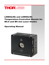
Physical Description
Item Description Item Description
1 Keyboard 5 Console Stand
2 LCD Display 6 Microprocessor Reset Switch
3 Optical Head Connection 7 RS-232 Interface Connection
4 Battery Compartment 8 Power Adapter Connection
The power meter console uses simple key commands to operate the unit.
Section 3.0 Operating Instructions
Figure 1.
6
Doc 2614-D04- RevE
02-07-02

7
Range Key
Pressing the range key will cycle the full-scale reading of the meter in decade steps (i.e. 10µW, 100µW, 1000µW,
10mW,100mW for the S120A / S122A optical heads or 100mW, 1000mW, 10W, 100W for the thermal heads) to allow
the appropriate display setting for a given laser power.
Note: Because the photodiode response is wavelength dependent, it is possible that the meter may reach a maximum
limit on the measurable power before the full-scale value is reached. If this happens, the unit will display an error
message, "OVERLOAD" across the display. It will be necessary to increase the range or attenuate the beam before a
valid measurement can be made.
Automatic Nulling
The S110 power meter provides an easy to use nulling feature to automatically zero the display. This is useful for sub-
tracting background light levels. To activate the nulling feature, simply press the “UP” arrow key. The unit will latch the
current power reading and subtract it from the displayed readings. The latched value is displayed below the bar graph
as reference. To exit the nulling mode, simply press the down arrow key.
Note: The bar graph display is not affected by the nulling mode to provide a full-scale power indication. Also, the nulling
feature is not available while in the zoom mode.
Auto Shutdown
The Auto Shutdown feature will place the console into a power down mode if the unit is idle for one hour. Every time a
key is pressed or a serial port command is received the auto shutdown timer will reset. This feature is designed to main-
tain the battery charge when the unit is not being used. This option can be disabled in the "System Setup" menu.
However, it will be enabled during the next power up.
Zoom Mode
The Zoom mode is used to adjust the offset and scaling of the bargraph to maximize the sensitivity of the bar-graph.
First, the bar-graph is adjusted with an offset to increase the full scale span of the bar. Secondly, adjusting the bar-graph
scaling can increase the sensitivity of the bar-graph. The Zoom mode is useful for beam alignment and laser tuning. The
upper and lower limits of the bar graph are displayed for convenient reference.
Pressing the zoom key while in the text display mode will put the unit in the zoom mode as indicated by the zoom factor
display above the power readings. The unit will automatically calculate an offset which will shift the displayed bar value
to 10% of the previous display (prior to entering the zoom mode). If the unit is in overload (i.e. the input power is too
high for the given range setting), the system will enter the Auto Zoom mode and attempt to bring the unit out of
saturation by incrementally adding an offset to the preamp circuit.
When in the zoom mode, the left and right arrow keys will change the displayed resolution of the bar graph by 1x, 2x,
and 3x up to 10x. The upper to lower range of the bar is displayed just below the bar graph region and is automatically
updated as the scaling is changed. If 10x is selected, pressing the right arrow key will re-center the zoom window
around the current power reading.
The up and down arrow keys can be used to shift the bar graph up or down by 10% as needed to keep the bar graph in
the display range.
To exit the zoom mode, simply press the Zoom key and the display will return to the Normal Text display. Pressing the
Range key will also exit the Zoom mode.
Note: the Zoom mode is only available on the S120 and S122 systems.
Menu Navigation
The menu system is easily navigated by using the up and down arrow keys. The current field is highlighted in reverse
font text. Pressing the “MENU/ENTER” key selects the highlighted field.
Doc 2614-D04- RevE
02-07-02

8
Display Mode Menu
• Normal Text – Selects the Normal Text Display mode
• X-Y Graph – Selects the power vs. time graph mode. Pressing the “MENU” key while in this mode brings up
the options menu for the graph display.
• Statistics – Selects the statistics display mode, which will display the Min,Max,Mean, and Standard Deviation
for a set of sampled data. The data set size is selected in the Stats Options menu which can be entered
while in the Statistics mode by pressing the “MENU” key.
• Prev Screen – returns to the previous menu.
• Exit – Terminates directly to the selected display mode (Text/Graph/Stats).
Measurement Menus
• Lambda – Selects the operating wavelength. To change the wavelength, highlight this field and press the
“MENU” button. Use the UP and DOWN arrow keys to select the operating wavelength. When finished, press
the “MENU” key to accept the value.
• # Avgs – Enter the number of samples per data point. This is useful for reducing uncorrelated noise.
• Units – Selects mW or dBm on the display. This only affects the displayed measurement (i.e. numbers in large
font). All serial port communication will maintain the power readings in watts.
• Prev Screen – Returns to the previous menu.
• Exit – Terminates directly to the selected display mode (Text/Graph/Stats).
Comm Setup Menu
• Baud Rate - Sets the serial port baud rate (format: 8 data, 1 stop, no parity, no handshake).
• Enable - Before transmission can start the serial port must be enabled by selecting this option.
• Prev Screen – Returns to the previous menu.
• Exit – Terminates directly to the selected display mode (Text/Graph/Stats).
System Setup Menu
• Calibrate System – This is used for calibrating the system. The offsets at each gain setting are measured and
used for compensating the raw data measurement. When the option is selected, the unit will display the
message "Cover Power Head." To use this feature, the optical head aperture must be blocked completely of
all light. Press any key to begin calibration, which will take approximately 20 seconds to complete.
• Restore Dflts – This is used to reset the internal parameters to the default values (same values as a
hard reset).
• Head and Verification Info – Display the optical head serial number, model number and the firmware version.
• Auto Shtdn – Enables and disables the automatic shutdown. This will default to On for every power up.
• Prev Screen –Returns to the previous menu.
• Exit – Terminates directly to the selected display mode (Text/Graph/Stats).
Display Contrast Adjustment
While in the System Setup Menu, the contrast on the LCD display can be adjusted by pressing the Left and Right
arrow keys.
Backlight
Pressing the backlight key (lower left corner of keypad) will turn the display backlight on to allow easier viewing in dark
rooms. The light will automatically turn off after approximately 30 seconds to conserve the batteries.
Doc 2614-D04- RevE
02-07-02

Battery Charging
The console uses four AA NiMH rechargeable batteries. Under normal instances, the unit should run for 16 hours or
more before needing to recharge the batteries (less if the backlight is used). When the battery charge level drops, a low
battery indicator will be displayed in the upper right region of the display (looks like a battery with a plus sign in the mid-
dle). If the low battery symbol appears, the unit should be charged to avoid losing measurement accuracy.
To charge the batteries, simply plug the 9VDC adapter (supplied with the system) into the side of the console and plug
into a suitable AC outlet. It takes approximately 3 hours to fully charge the batteries.
The unit can be operated normally while the AC adapter is plugged in, the batteries will charge even when the unit is
turned on.
The S120 comes standard with on RS-232 serial interface port for remote control and monitoring. The serial port can be
connected to a PC running an ASCII terminal emulator program, such as Windows HyperTerminal (see Appendix A), to
remotely access the S110 features. Serial Port Pin Outs
Serial Port Parameters:
Baud Rate: 2400 to 19200
Data Bits: 8
Stop Bits: 1
Parity: none
Handshake: none
Section 4.0 Serial Interface
DB9F pin Signal
1,7,8,9 no connect
2 TxD (from S110)
3 RxD (to S110)
4 connected to pin 6
5 Signal Ground
6 connected to 4
Table 4.1 - Power Meter Serial Interface Protocol
Command Function Argument Return
P Read current power no ASCII string of power in uW and terminated with
CR
C Continuous power reading none Same as ‘P’command except the power will be
sent in a continuous stream.
S Stop continuous power reading none "Continuous Stopped"
L1Set wavelength (nm) wavelength (in nm) OK: wavelength echoed
Fail: 0
R Set preamp range 1 – 10µW 5 – 100mW OK: returns choice
2 – 100µW 6 – 1000mW Fail: 0
Optical Heads use gains 1-5 3 – 1000µW 7 – 10W
Thermal Heads use gains 5-8 4 – 10mW 8 – 100W
H Read head info None Head ID (S120A, S122A, S210A, or S212A)
Head Serial Number
Firmware Rev #
A Set number of averages N (1 to 1000) OK: N
Fail: 0
U Display units for console only 0: mW OK: mW or dBm
1: dBm Fail: 0
D Set display mode 1: normal screen OK: returns choice
2: statistics Fail: 0
3: graph
V2Toggle Verbose mode none Verbose ON
Verbose OFF
Z Zap mem and restore defaults none "Defaults restored"
T Auto Shutdown Enable/Disable 0: disable
1: enable
9
Doc 2614-D04- RevE
02-07-02

10
1. The wavelength data is limited to 5nm increments. A wavelength with a LSB not equal to 0 or 5nm will be rounded to the
nearest 5nm.
2. The Verbose command will display an information request when selecting a function with an argument. This is
useful to prompt the user to enter required information. This command would normally be disabled when using software to
control the console.(ex Type "L" responds: "Enter the wavelength:", the user enters <wavelength> + Enter)
Note: all arguments and return values are terminated with a carriage return ("\r" or ASCII code 13).
Section 5.0 Specifications
System Specifications
Operating Temperature: 5ºC to 40ºC
Storage Temperature: 5ºC to 40ºC
Size: 7.75" x 4" x 1.75"
Weight: 1.2 lbs.
Optical Head Connection: Female DB9 located on the top of the console
Microprocessor Reset: Recessed pushbutton located on the left side of the console
Measurement Averaging: 1 to 100 samples per average (SPA)
AC Power Adapter: 9VDC @ 1.3A Switching Supply
AC Input Voltage: 100-240VAC, 50-60Hz, @ 15W
Display Specifications Display Type: LCD graphic display, 128 x 64 pixels
Backlight: LED
Backlight Timeout: 30 seconds
Text Display Update Rate: 3Hz
Measurement Font Height: 0.55 inch
Standard Font Height: 0.18 inch
Display Resolution: +/- 1 LSB
Analog Display: High Resolution Bar Graph with Dynamic Zoom for enhanced measurement
resolution.
Analog Display Update Rate: 10Hz update rate.
Display Modes: Normal Text with large fonts.
X-Y Graph mode - real-time, oscilloscope-like plotting of power.
Statistics Mode - real time viewing of beam stats.
Battery Charger Specifications
Battery Charger: Included in console, will charge batteries while operating unit.
Charge Current: 0.5A
Max Charge Time: 4hrs 20min
Typ. Charge Time: 3hrs (using ThorLabs supplied batteries)
Battery Type: NiMH
Battery Capacity: 1000 to 1800 mAh (1300 mAh from factory)
Battery Quantity / Size: 4 AA
Typ. Operating Time: 16 hour (without backlight)
Serial Interface continued
Doc 2614-D04- RevE
02-07-02

Battery Charger Supply Specifications
Charger Supply Type: Switching Mode (external)
Input: AC 100V – 240VAC 50Hz – 60Hz 0.3A
Output: 9V DC @ 1.33A
Thorlabs Model: 4004-9V-1.33A
Pinout:
Serial Port Specifications
Serial Interface: RS-232
Serial Format: 8 data, 1 stop and no parity bits
Baud Rates: 2400, 4800, 9600 and 19,200
Serial Interface Cable: S110 to standard DB9 female, included with unit.
Available Drivers: LabView
LabView Compatibility: Ver. 5.5 and higher
Section 5.0 Specifications continued
11
Doc 2614-D04- RevE
02-07-02

LASER SOURCES
LASER DIODES LD AND TEC CONTROLLERS
ND FILTERS
FIBER COLLIMATION
MOUNTING ADAPTERS
FIBER PATCH CABLES
FIBER PIGTAILS
BARE FIBER
TERMINALS
TE-COOLED LASER
MOUNT
TCLDM9,TCLDM3,
The S1 and S3 system are available
and ready to ship.
For details call (973) 579-7227,
or visit: www.thorlabs.com
Sanyo, Mitisubishi, Hitachi,
Toshiba, Sharp
• 635nm-1550nm
• SPECIAL LOW PRICES
Thorlabs’temperature controlled
laser mount allows precise
temperature regulation of a laser
diode. This mount is plug-and-play
compatible with our laser diode
driver and TEC controller.
These Absorptive Neutral Density
filters (unlike metallic filters) are
manufactured from a family of Schott
glasses that have varying internal
absorption coefficients. By using three
different glasses (each with a unique
absorption) that are spectrally flat and
by differing filter thicknesses we are
able to manufacture this series of
Neutral Density filters. All data is
specified at 546nm. ReflectiveND
filters are also available.
High-quality ceramic FC
connectors. Each cable is
individually tested to ensure
low back-reflection (Return
Loss) at fiber-to-fiber junc-
tions. Available from stock.
NEW UNIVERSAL DESIGN!
Compatable with FC, ST &
SMA Connectors
For applications where a
temporary fiber termination is
desired, our Bare Fiber
Terminators are the solution.
They are reusable, and can
be easily cleaned out if the
fiber breaks inside the
connector by using clean out
wires (WC100). These termi-
nators are designed to
mechanically hold fibers in
standard connectors, which
are sold separately.
Our Fiber Collimation Packages
are designed to focus a collimated
laser beam onto the end of a fiber
optic. The packages are factory
aligned so that the focusing lens is
one focal length away from the
input (or output) end of the fiber.
The SM1-Series fiber adapters thread
directly onto PDA Series detectors for
convenient attachment of optic fibers.
They can also be used with the SM1-
series stackable lens tubes
We carry a full line of LD and TEC
controllers. Visit our website at:
www.thorlabs.com
12
Single Mode and Multimode pigtails
available from stock. Call or email
Technical Support
for Volume or
CustomQuotes
(973 )579-7227
Section 6.0 Accessories
Doc 2614-D04- RevE
02-07-02

Section 6.0 Maintenance & Support
Troubleshooting & Frequently Asked Questions
No Display
Make sure the batteries are charged and plug the AC adapter into the unit if necessary. When the low
battery symbol appears, the AC adapter should be plugged into the unit to recharge the batteries.
Display does not respond
Although not common, the unit may lock up if the batteries were drained too low during operation. Plug
the AC adapter into the unit and reset the console (by inserting a straightened paper clip into the reset
button access hole and pressing the button).
Power displayed does not agree with expected results
• Make sure the correct wavelength, range, and sensor head are being used for your application.
• It may be necessary to do an offset calibration of the unit (see section 3 – Calibrate System).
• Background light may also affect the reading. This can be removed by using the auto nulling mode
Overload Message Appears
This indicates that the input power level has saturated the sensor electronics. Switch to a higher range or
attenuate the beam externally.
Note: The S120A and S122A sensor heads have a 1.035-40 thread to allow easy attachment of mounted
ND filters (available separately from ThorLabs).
Power display values change too quickly
Amplitude variations or noise in the laser beam typically causes this. Increase the number of averages to
filter out random noise.
Note: At the lowest range setting (10µW), some system noise may be prevalent when the number of
averages is low. It may be necessary to increase the number of averages to avoid this.
Display too dim or too dark
Adjust the display contrast by entering the System Setup Mode and use the right key to increase the
contrast and the left key to decrease the contrast.
Battery Indicator Appears
The low battery symbol looks like a small black battery with a cross in the middle. If this appears during
operation, charge the batteries by plugging the AC adapter into the system. The unit can still be operated
while charging the batteries. Also, it is not necessary to turn the unit off before plugging in the charger.
Batteries do not hold a charge
Under normal conditions, a fully charged set of batteries should operate the unit for up to 16 hours
(shorter if the back light is used frequently). When the batteries fail to hold a charge they will need to be
replaced. Contact ThorLabs for a replacement set of batteries.
Be sure to dispose of the old batteries properly.
13
Doc 2614-D04- RevE
02-07-02

Troubleshooting & Frequently Asked Questions continued
Displaying firmware version
The firmware version number is easily found by selecting the Head & Ver. Info option from the SYSTEM
SETUP menu. It is also available in the System Information screen during startup.
How do I change the vertical scaling in the X-Y mode?
Pressing the MENU button while in the X-Y Graph mode will bring up the Graph Menu. The upper
(Ymax) and lower (Ymin) limits of the vertical display can be changed individually to adjust both the
offset and scaling of the display. The values scroll through a scaled 1-2-5 sequence (similar to an
oscilloscope).
How do I change the horizontal timing in the X-Y mode?
The horizontal timing is also changed in the Graph Menu mode by changing the value of Tstep. This
sets the time between plotted points on the screen. The lowest value is labeled FAST and is limited by
the display speed of the unit.
Resetting the unit
The S110 uses a sophisticated microprocessor with non-volatile memory to store system values when
the unit is powered off. Under normal conditions, it should not be necessary to reset the system.
However, if the system locks up and does not respond to any key presses, it may be necessary to reset
the console.
A miniature pushbutton switch is located on the left side of the console which, when pressed, will com
pletely reset the console to the default values. Note: the calibration accuracy is not effected since the
sensor heads store their calibration data in the optical heads.
To activate the reset, insert a pin or a straightened paper clip into the small access hole located on the
left side of the console and momentarily press the reset button. The unit will turn on, read the head data
and start normal operation using the default settings. It may be necessary to set the system parameters
(wavelength, range, number of averages, etc.) to the desired values. Also, a system-offset calibration
should be performed after a reset.
Calibrating the Unit
The spectral calibration data is stored in EPROM memory attached to each sensor. As long as the
sensor has not been exposed to excessive optical power and the console has not been physically
damaged, the calibration should be very stable over long periods of time (well over a year).
Since ThorLabs cannot anticipate the requirements of each customer’s quality system, the re-calibration
schedule is determined by the customer. However, ThorLabs suggests the optical heads be re-calibrated
every year. For a nominal fee, ThorLabs will recalibrate the power meter and sensor head. Please
contact customer service to make the appropriate arrangements.
14
Doc 2614-D04- RevE
02-07-02

System Offset Calibration
The S110 has a feature that will measure the DC offset of the system at each gain setting and store these values in non-
volatile memory. This increases the measurement accuracy of low-level signals. To activate this feature, follow the pro-
cedure below:
• Completely block the sensor head from any input light, including room light. Any residual light will cause an
error in the offset measurement.
• Select the SYSTEM SETUP MENU
• Select the Calibrate Sys menu option and the unit will begin measuring the offsets at each gain setting. The
results will be displayed on the screen as they are completed. Typical values are from 480 to 520. If the
reported numbers are too high, it is most likely that the sensor is not completely blocked from light.
• After the procedure is complete, exit the menu and resume normal operation. These values will be stored in
memory until either the head is changed or a system reset is performed.
Cleaning
To clean the console, use a mild detergent and damp cloth. Do not soak the unit in water or use solvent based cleaners.
When cleaning the aperture filter on the semiconductor sensor heads (S120A and S122A), treat it as any other fine
optic. Gently blow off any debris using compressed air and wipe gently with an optic tissue wetted with propanol.
The sensors on the thermal heads cannot be cleaned. Gently blow off any debris using compressed air. If any scratches
or other signs of damage remain on the sensor area, contact Thorlabs service department for repair or replacement.
Technical Support
You may use any of the following methods to contact Thorlabs in case of difficulty or if you have questions regarding
your power meter. Please take note of the firmware revision level to help us assist you.
www.thorlabs.com Our website will have up-to-date application notes and frequently asked questions regarding
our products.
[email protected] You can send a detailed email message and one of our application engineers
will respond promptly (within 1 business day).
Fax: (973) 300-3600
Phone: (973) 579-7227
Mail: Thorlabs, Inc.
435 Route 206N
Newton, NJ 07860
15
Doc 2614-D04- RevE
02-07-02

The S110 uses a simple ASCII character command set to interface to a remote serial device. This allows the use of a
ASCII terminal emulator running on a PC, that is connected to the S110 through a serial port, to easily talk to the power
meter.
The following procedure describes how to set up HyperTerminal as an ASCII terminal emulator. HyperTerminal is a
program that is shipped with Windows 95/98/NT.
1. Run HyperTerminal by selecting the following through the Start menus:
Start Menu -> Programs -> Accessories -> HyperTerminal -> HyperTerminal
The program will ask for the following information:
2. "You need to install a modem before you can make a connection" - No
3. "Enter Name for Connection" - Enter "ASCII" of some other convenient name to save as.
4. "Connect Using" - Select COM1 or COM2 (whichever serial port the S110 is attached to).
5. Enter the following in the Properties window
Baud: 9600
Data bits: 8
Parity: None
Stop bits: 1
Flow control: Hardware
After entering all of the above, a blank screen will appear.
6. Turn the S110 console on and select the following:
Press Menu > Comm Setup > Enable: Yes
7. An S110 title line will appear on the HyperTerminal display. The connection is now active and ready for a
command.
If no characters appear on the screen, check that the port settings matches the serial port connected to the S110. If a
bunch of symbols or nonsensical characters appear, check the baud rate and data bits in the Properties window (found
in the File pull-down menu) and verify they match the S110 baud rate setting (found in Menu > Comm Setup > Baud
Rate.
* At the end of the session, select save to save these settings for a later session.
Note: For Windows 2000
1.A Run HyperTerminal by selecting the following through the start menus-
Start -> Programs -> Accessories -> Communications -> HyperTerminal
Continue with Step 2 above.
Appendix A:Windows HyperTerminal Setup for the S110 Console
16
Doc 2614-D04- RevE
02-07-02

With the Power Meter VI, the user can easily incorporate the Power Meter into an automated system using LabView.
The commands used with this VI are the same used with the Serial Interface, except with the Power Meter VI, there is
no "Continuous Power Reading" ("C") command, no "Stop continuous power reading" ("S") command, or "Toggle
Verbose mode" ("V") command. Unlike the Serial Interface, you only have to enter the letter corresponding to the com-
mand and argument (if any). No carriage return is required.
The following is list of all the parameters and their descriptions.
COM Port Number: This is the COM port through which the program will communicate to the Power Meter. For PC,
0 = COM 1, 1 = COM 2, etc. For Mac, 0 = Modem, 1 = Printer, etc. All other serial port
parameters are the default values (Data Bits: 8, Stop Bits: 1, Parity: None) and do not require
the user to specify.
Baud Rate: The default Baud Rate for the VI and the Power Meter is 9600. The unit can also operate at
19200, 4800, and 2400. If you plan to operate the Power Meter at a baud rate of 9600, you do
not need to wire this terminal.
Command: Here the user can use any of the commands specified in this manual. All commands are single
ASCII characters (string).
Argument: For some of the commands used by the Power Meter, an argument is required. For example, if
you want to change the wavelength to 750nm, you would enter the string "L" as the Command
and the string "750" as the Argument.
Serial Error: If an error occurs when the VI tries to communicate with the serial port, this terminal will return a
TRUE value.
Read Timeout: If the Timeout expires before the Command sent to the serial port is executed, the VI will
terminate, returning a TRUE value to this terminal. The default Timeout is 5 seconds.
Command Fail: If the VI cannot complete the Command it was given (i.e. the user send an invalid Command or
Argument), it will return a TRUE value to this terminal.
Output: The VI will return a string containing the value resulting from the Command it was given (i.e. if
the command "P" is sent, the VI will return a string with the value 2.487e1).
This information is also available within LabView under the Show Help option.
Also, be sure to check ThorLabs website (www.thorlabs.com) for updates to the Power Meter drivers and software as
they become available.
Appendix B: S110 LabViewDriver Instructions
Thor
Power
meter
Com Port Number
Baud Rate
Command
Argument
Serial Error
Read Timeout
Command Fail
Output
17
Doc 2614-D04- RevE
02-07-02

Appendix C: SPEC SHEET: S120A Silicon Power Meter Optical Head
Description: S120A
The S120A is an optical power meter head designed to be used directly with the ThorLabs S110 console system to
measure light over the visible wavelength range of 400 to 1100nm and provide a NIST traceable optical power meas-
urement. The optical power meter head will detect light over the power range of 20nW to 10mW. An EPROM located in
the DB9 mating connector will store the NIST calibrated spectral response curve required to provide an accurate power
reading.
The S120A housing includes a threaded input that is compatible with any number of ThorLabs 1" threaded acces-
sories. This allows convenient mounting of external optics, light filters, and apertures. An 8-32 (M4 for the S120A/M)
threaded mounting hole is provided to accommodate posts and post holders.
Mechanical Drawing:
ND Filter Frt. Surface
Detector Surface
0.120
0.235
0.27"
8-32 Tap
(M4-0.5 for metric vers.)
0.90"
0.10"
3 Ft. Long
Interface Cable
ø0.39" Sensor Aperture
1.035-40 Thread
ø1.20"
Note: The above graphs are typical values since the power is dependent on the spectral responsivity, which will vary from
detector to detector.
Specifications:
Spectra Range: 400 – 1100nm Optical Power Range: 20nW – 10mW
Sensor: Silicon Resolution: 3.5nW
Sensor Size: 10mm x 10mm sq. Measurement Standard: NIST Traceable
(0.39" x 0.39") Measurement Uncertainty: +/- 5%
Input Aperture: 0.39" Diameter Operating Temperature: 5ºC to 40ºC
Distance to ND Filter: 0.120 inches Storage Temperature: 5ºC to 40ºC
Distance to Detector: 0.235 inches
Cleaning and Maintenance:
There are no serviceable parts in the S120A optical head. The housing may be cleaned by wiping with a soft damp
cloth. When cleaning the aperture filter of the S120A, treat it as any other fine optic. Gently blow off any debris using
compressed air and wipe gently with an optic tissue wetted with propanol. If you suspect a problem with your S120A
please call ThorLabs and an engineer will be happy to assist you.
As long as the sensor has not been exposed to excessive optical power, the calibration should be very stable over long
periods of time (well over a year). However, the detector should be calibrated once a year to ensure accuracy.
18
Doc 2614-D04- RevE
02-07-02

Appendix C: SPEC SHEET: S122A Germanium Power Meter Optical Head
Description :S122A
The S122A is an optical power meter head designed to be used directly with the ThorLabs S110 console system to
measure light over the visible wavelength range of 700 to 1800nm and provide a NIST traceable optical power measure-
ment. The optical power meter head will detect light over the power range of 20nW to 10mW. An EPROM located in the
DB9 mating connector will store the NIST calibrated spectral response curve required to provide an accurate
power reading.
The S122A housing includes a threaded input that is compatible with any number of ThorLabs 1" threaded accessories.
This allows convenient mounting of external optics, light filters, and apertures. An 8-32 (M4 for the S122A/M) threaded
mounting hole is provided to accommodate posts and post holders.
Cleaning and Maintenance:
There are no serviceable parts in the S122A optical head. The housing may be cleaned by wiping with a soft damp cloth.
When cleaning the aperture filter of the S122A, treat it as any other fine optic. Gently blow off any debris using compressed
air and wipe gently with an optic tissue wetted with propanol. If you suspect a problem with your S122A please call
ThorLabs and an engineer will be happy to assist you.
As long as the sensor has not been exposed to excessive optical power, the calibration should be very stable over long
periods of time (well over a year). However, the detector should be calibrated once a year to ensure accuracy.
ND Filter Frt. Surface
Detector Surface
0.120
0.235
0.27"
8-32 Tap
(M4-0.5 for metric vers.)
0.90"
0.10"
3 Ft. Long
Interface Cable
ø0.20" Sensor Aperture
1.035-40 Thread
ø1.20"
Mechanical Drawing:
Note: The above graphs are typical values since the power is dependent on the spectral responsivity, which will vary from detector to detector.
Specifications:
Spectra Range: 700 – 1800nm Optical Power Range: 10nW – 5mW
Sensor: Germanium Resolution: 1nW
Sensor Size: 5mm dia. Measurement Standard: NIST Traceable
Input Aperture: 0.39" Diameter Measurement Uncertainty: +/- 5%
Distance to ND Filter: 0.120 inches Operating Temperature: 5ºC to 40ºC
Distance to Detector: 0.235 inches Storage Temperature: 5ºC to 40ºC
19
Doc 2614-D04- RevE
02-07-02

Appendix C: SPEC SHEET: S210A 3W Thermal Power Meter Head
Description: S210A
The S210A is a thermal power meter head designed to be used directly with the ThorLabs S110 console system to
measure light over the broadband wavelength range of 250nm to 10.6mm and provide a NIST traceable optical power
measurement. The thermal power meter head will detect light over the power range of 10mW to 3W. An EPROM located
in the DB9 mating connector will store the head and serial number information, necessary for the console to adjust the
appropriate settings.
The S210A housing includes a 3⁄4- 32 threaded input that is compatible with any number of ThorLabs 1" threaded acces-
sories, when using ThorLabs SM1 to 3⁄4-32 adapter. This allows convenient mounting of external optics, light filters, fiber
adapters, and apertures. An 8-32 threaded mounting hole is provided to accommodate posts and post holders. An 8-32
to M4 adapter is provided for metric versions.
Specifications:
Spectra Range: 250nm – 10.6mm Optical Damage Threshold: 200W/cm2CW, 3.3J/cm2
Sensor: Thermal (1ms pulse@1064)
Input Aperture / Sensor: 3⁄4" dia. 50mJ/cm2(20ns pulse@1064)
Aperture Thread: 3⁄4" - 32 Measurement Uncertainty: +/- 5%, NIST Traceable
Optical Power Range: 10mW – 3W Operating Temperature: 5ºC to 40ºC
Resolution: 1mW Storage Temperature: 5ºC to 40ºC
Cleaning and Maintenance:
There are no serviceable parts in the S210A thermal head. The housing may be cleaned by wiping with a soft damp
cloth. The sensors on the thermal heads cannot be cleaned. Gently blow off any debris using compressed air. If any
scratches or other signs of damage remain on the sensor area, contact ThorLabs service department for repair or
replacement. If you suspect a problem with your S210A please call ThorLabs and an engineer will be happy to
assist you.
As long as the sensor has not been exposed to excessive optical power, the calibration should be very stable over long
periods of time (well over a year). However, the detector should be calibrated once a year to ensure accuracy
ø3/4 Sensor Aperture
3/4-32 Threaded Aperture 3W Power Head
8-32 Tap
(M4-0.5 adapter for
metric vers.)
1.30"
Detector Surface
0.315 (8 mm)
0.600
Mechanical Drawing:
20
Doc 2614-D04- RevE
02-07-02
/