Page is loading ...

Installation and
Operating Instructions
8000-1794-01, Rev. A (11 pages)
Copyright © 1999 by Sensormatic Electronics Corporation
1 INSTALLATION AND
OPERATING INSTRUCTIONS
1020 Series
30/60-Watt LED
Infrared Illuminator
About this Document
This document describes the installation and
operating procedures for the American Dynamics
model 1020 30/60-watt LED Infrared Illuminator
Series. The light produced by the 1020 Series is
invisible to the human eye which makes it ideally
suited for covert security operations. The 30-watt
model is designed for indoor operation and small
outdoor areas. The 60-watt model is most effective
in an outdoor environment where higher power is
required.
If you need assistance, call...
American Dynamics Technical Support Center:
Toll free: 800.442.2225
Fax: 914.624.7685
The software/firmware furnished with this equipment is confidential
to, and copyrighted by, AMERICAN DYNAMICS. It is not to be
copied or disclosed in any manner without the express written consent
of AMERICAN DYNAMICS. The software/firmware is furnished to
the purchaser under a license for use on a single system.
Information furnished by AMERICAN DYNAMICS is believed to be
accurate and reliable. However, no responsibility is assumed by
AMERICAN DYNAMICS for its use; nor for any infringements of
other rights of third parties which may result from its use. No license
is granted by implications or otherwise under any patent or patent
rights of AMERICAN DYNAMICS.
Contents
Warnings and Cautions.................................................2
Before You Begin.........................................................2
Unpacking and Inspection.........................................2
Maintenance..............................................................2
Installation and Service.............................................2
Description....................................................................2
Features.....................................................................2
Over-voltage shut-off............................................2
Temperature-related shut-off ................................2
Power Supply Selection ............................................2
Twilight Switch.........................................................3
Power Supply Installation.............................................3
General Safety...........................................................3
1040-3060PSA Power Supply Installation................3
Power Supply Wiring....................................................4
Installer Wiring.........................................................5
Primary Connections.............................................5
Secondary Connections.........................................6
Power Supply Operation...............................................6
120Vac/230Vac Operation........................................6
1040-3060PSA Power Supply Output Voltage.........6
Measuring the 1040-3060PSA Output Voltage.........6
Adjusting the 1040-3060PSA Output Voltage..........6
Two-Wire Connections.................................................6
Illuminator to Power Supply Connection (2-Wire)...7
Four-Wire Connections.................................................7
Jumper Clip Removal................................................7
Illuminator to Power Supply Connection (4-Wire)...7
Troubleshooting............................................................8
Dimensions ...................................................................9
Specifications..............................................................10
Declarations ................................................................11
Regulatory Compliance...........................................11
Other Declarations ..................................................11

INSTALLATION AND
OPERATING INSTRUCTIONS
1020 SERIES 30/60-WATT LED INFARED ILLUMINATOR
8000-1794-01, REV. A
2
Warnings and Cautions
The installation of this product should be made by
qualified service personnel and should conform to
all local codes.
WARNING: To prevent serious vision damage,
install the Illuminator so that the distance between
the Illuminator and the closest possible human
contact is no less than 1.22m (4ft).
WARNING: To reduce the risk of electrical shock,
do not remove covers or back of the power supply.
No user-serviceable parts are inside. Refer
servicing to qualified service personnel.
WARNING: This product generates, uses, and can
radiate radio frequency energy and if not installed
and used in accordance with the instructions
manual, may cause interference to radio
communications. It has been tested and found to
comply with the limits for a Class A computing
device pursuant to Part 15 of FCC Rules.
Before You Begin
Unpacking and Inspection
Unpack carefully. This is an electronic product and
should be handled as such. Compare the items
received with the packing list with your order.
Be sure to save:
• The shipping cartons and insert pieces. They
are the safest material in which to make future
shipments of the product.
• The IMPORTANT SAFEGUARDS sheet.
• These Installation and Operating Instructions.
Maintenance
User maintenance of this unit is limited to external
cleaning and inspection. For specific
recommendations refer to the IMPORTANT
SAFEGUARDS sheet packaged with this product.
Installation and Service
If you require information during installation of this
product or if service seems necessary, contact the
American Dynamics Technical Support Center at
800.442.2225. You must obtain a Return
Authorization Number and shipping instructions
before returning any product for service.
Do not attempt to service this product yourself.
Opening or removing covers may expose you to
dangerous voltages or other hazards. Refer all
servicing to qualified personnel.
Description
The American Dynamics series of Infrared
Illuminators provide outstanding results when used
with IR sensitive B/W cameras.
The light produced by the 1020 Series Illuminators
is invisible to the human eye, making these units
excellent for covert operations or where the use of
visible lighting is not possible.
The 1020 Series Illuminator uses 22 rows of LEDs
(Light Emitting Diodes) to consistently produce
peak wavelength infrared light. All 22 rows of
LEDs are wired in parallel to prevent Illuminator
shutdown should one individual LED, or one row of
LEDs, fail.
American Dynamics offers this Illuminator in 30-
watt and 60-watt configurations. The 30-watt
Illuminator provides coverage for indoor and small
outdoor areas where a range of approximately
20m (66ft) is needed. Where greater outside
distance is required, the 60-watt Illuminators
provide coverage up from 35m (115ft) to 55m
(180ft).
Features
Over-voltage shut-off
The 1020 Series Illuminators are designed with
over-voltage circuitry to switch the Illuminator off in
case of voltage surges greater than 15 Vdc. The
unit switches on once the voltage drops below the
15 Vdc level.
Temperature-related shut-off
The 1020 Series Illuminators are designed to shut
off when temperatures exceed 70°C (158°F). The
unit switches on immediately after the temperature
drops below this limit.
Power Supply Selection
A power supply is not included with the 1020
Series Illuminators. The user can select an
independent manufacturer's power supply or
choose the 1040-3060PSA Power Supply
produced by American Dynamics.
When selecting a power supply, bear in mind that
the 1020 Series Illuminators require a stable 13.5
± 0.5 Vdc input.
• A power supply with large voltage output
fluctuations will drive the Illuminator protection
circuitry into shut-down mode.

INSTALLATION AND
OPERATING INSTRUCTIONS
1020 SERIES 30/60-WATT LED INFARED ILLUMINATOR
8000-1794-01, REV. A
3
• A power supply with voltage levels below the
operational requirements of the Illuminator will
result in substantial loss of IR energy output,
causing a loss of viewing range.
• A power supply with remote sensing
capabilities is desirable. Remote sensing
compensates for voltage drops across
extended lengths of power supply-to-Illuminator
connection wiring. (Remote sensing capability
is defined as a power supply having internal
circuitry to automatically compensate for any
voltage drop caused by changes in the load
demand and/or long wire lengths between the
power supply and the Illuminator.)
Twilight Switch
American Dynamics recommends routing the AC
source voltage through a twilight switch (not
supplied). A daylight activated on/off switch
prevents the IR-Illuminator from possible over-
heating by intense sunlight.
Power Supply Installation
This installation should be made by qualified
service personnel and should conform to all local
codes. Safeguards must be taken to avoid
unintentional operation by employees and
maintenance personnel working about the
premises.
General Safety
The instructions in this document are for the
installer's safety and should be observed without
exception:
• Before installation, become familiar with all the
special features and warnings associated with
this equipment. Once installation is complete,
store this document in a safe, convenient
location for future reference.
• At close range, Infrared light can seriously
damage a person's vision. Install this
Illuminator in such a manner as to provide a
minimum safety zone of 1.22m (4ft) between
the Illuminator and the closest possible human
contact.
1040-3060PSA Power Supply
Installation
The 1040-3060PSA Power Supply is provided with
a NEMA-4 weatherproof enclosure. Mount the
power supply close to the Illuminator installation
site.
Notes:
• Inspect the area around the proposed
installation site for wires, pipes, or obstructions
that may interfere with the installation.
• Mount all hardware (twilight switches, junction
boxes, power supply, and Illuminator) before
laying out conduit and wiring (Figure 2).
• The installation shown in Figure 2is for
illustration purposes only. Hardware items such
as conduit, junction boxes, twilight switches,
and inter-connection wiring are user-supplied.
The power supply enclosure has four mounting
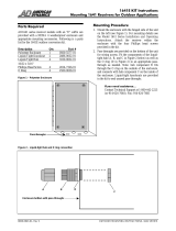
holes for direct wall or panel mounting (Figure 1).
Figure 1. Weatherproof enclosure mounting
dimensions
• Confirm a structurally sound surface for the
mounting location.
• Make a template of the enclosure mounting
holes or place the enclosure against the
mounting surface and mark the four hole
locations.
• Drill the four holes and attach the enclosure to
the mounting surface.
152.4mm
(6.0")
273mm
(10.75")

INSTALLATION AND
OPERATING INSTRUCTIONS
1020 SERIES 30/60-WATT LED INFARED ILLUMINATOR
8000-1794-01, REV. A
4
Two conduit connectors are provided with the
NEMA-4 weatherproof enclosure. One 1/2-inch
(ID) connector for securing a length of flexible
conduit between the AC source and the power
supply enclosure. One 3/8-inch (ID) connector for
securing a length of flexible conduit between the
power supply enclosure and the Illuminator
junction box (Figure 2).
Figure 2. Typical power supply-to-illuminator
layout
8
1
Legend Description
A 120/230Vac source junction box (weatherproof)
B Power supply weatherproof housing
C Power supply
D Twilight switch (optional)
E 1/2" Conduit connector
F 3/8" Conduit connector
G Junction box (weatherproof)
H LED illuminator
• Install all conduit connectors hand-tight in the
appropriate holes. Do not tighten connectors at
this time.
• Measure and cut the conduit pieces to required
lengths.
• Remove conduit connectors from hardware
items and assemble connectors to conduit.
• Fit the components [B], [C], and [D] of the
liquid-tight hub (Figure 3) into an appropriate
pass-through.
Note: Hub [B] fits through the O-ring [D] on the
outside of the enclosure, and is secured by nut
[C] on the inside of the enclosure.
Figure 3. Liquid-tight hub and O-ring connection
• Place Sealing Nut [A] over the conduit end. Do
not tighten the Sealing Nut onto Hub [B] until all
components are in their final positions.
• Install conduit assemblies between hardware
items and tighten.
• Mount power supply unit in power supply
enclosure.
• Verify that all hardware is securely tightened
and weatherproofed.
Power Supply Wiring
The 1040-3060PSA Power Supply requires a
120Vac to 252Vac source voltage. Typical input
voltages are 120Vac and 230Vac.
CAUTION: Verify that the AC source voltage is
switched off and locked-out at the breaker panel.
• Determine the source of the 120Vac or 230Vac
to the power supply.
• Select the proper wire size (14AWG minimum)
between the AC source and the power supply
that conforms to local building codes.
• Starting at the AC source junction box, pull the
AC wires through the conduit (leave excess
wire at all junctions) and into the power supply
enclosure (Figure 2).
A
D
B
C
E
F
G
H
[A] Sealing nut [C] Nut
[B] Hub
[D] O-Ring

INSTALLATION AND
OPERATING INSTRUCTIONS
1020 SERIES 30/60-WATT LED INFARED ILLUMINATOR
8000-1794-01, REV. A
5
Note: Routing the AC source voltage through a
twilight switch (not provided) extends the
operational life of the 1020 Illuminator.
American Dynamics recommends using one
twilight switch (AD part number 1010/TS) to
operate a maximum of 10 power supplies.
• Do Not Connect Power Supply to Illuminator
At This Time.
• Connect the AC source wires to the appropriate
terminals on the twilight switch (if used) and
secure the twilight switch-box cover.
• Secure the AC source junction-box cover.
Installer Wiring
A qualified electrician should make all wiring
connections according to local codes. Do not
make connections to the switching power supply
unit or alter the factory pre-wiring between it and
the terminal strip.
Primary Connections
• Pass the primary (120V or 230V) wiring through
the previously installed 1/2-inch bushing
(Figure 4 and Figure 5).
• Open a ferrite clamp and route the wires
through it, then close the clamp.
• Secure the ferrite clamp to the inside of the
enclosure by means of the double-sided tape
provided.
• Tighten the bushing.
Caution: If necessary, trim the MOV surge
suppressor leads to keep them as short as
possible. After the leads are connected to the
terminal block, dress the leads to ensure they
do not contact other wiring or metallic objects.
• Connect the GREEN or GREEN/YELLOW
Primary Ground wire and one lead from each
MOV surge suppressor to terminal #3 (Ground)
(Figure 5).
• Connect the WHITE or BLUE Primary Neutral
wire and a lead from one MOV surge
suppressor to terminal #1 (Neutral).
• Connect the BLACK or BROWN Primary Line
wire and a lead from the other MOV surge
suppressor to terminal #2 (Line).
• Turn on the AC source voltage and verify that
the power supply outputs 13.5 ±0.1Vdc. Refer
to Measuring the 1040-3060PSA Output
Voltage, page 6.
• Turn off the AC power source.
Figure 4. Power supply enclosure layout
8
1
Figure 5. Source voltage connections
7
6
5
8
4
3
2
1
G
L
N
120/230Vac source
j
unction bo
x
(weatherproof)
Power supply
weatherproof enclosure
1/2" Conduit
connector
Power supply output
3/8" Conduit
connecto
r
Ferrite clamp
Power
supply
Terminal
strip
Power
supply
Terminal
strip
Ferrite
clamp
Power
supply
Factory
wiring
Terminal 120Vac 230Vac
NBlueWhite
LBlackBrown
G Green Green/Yellow
MOV surge
suppressor

INSTALLATION AND
OPERATING INSTRUCTIONS
1020 SERIES 30/60-WATT LED INFARED ILLUMINATOR
8000-1794-01, REV. A
6
Secondary Connections
• Pass the low-voltage wiring through the
previously installed 3/8-inch bushing (Figure 4).
• Open a ferrite clamp and route the wires
through it, then close the clamp.
• Secure the ferrite clamp to the inside of the
enclosure by means of the double-sided tape
provided.
• Tighten the bushing.
If using the 2-wire system, leave the two
jumpers in place between –S/-V and +S/+V. If
using the 4-wire system, remove the two
jumpers (Figure 6).
Note: Terminal #4 on the terminal strip is not
used.
• Connect Output –S (if used) to terminal #5
(Figure 4 and Figure 7).
• Connect Output –V to terminal #6.
• Connect Output +V to terminal #7.
• Connect Output +S to terminal #8.
Figure 6. Power supply terminal strip
+S +V -V -S FG L N
+S +V -V -S
Power Supply Operation
120Vac/230Vac Operation
The 1040-3060PSA Power Supply is designed to
operate on 120Vac to 230Vac, 50/60Hz without
the need for adjustment or jumpers.
1040-3060PSA Power Supply Output
Voltage
Before connecting the 1040-3060PSA Power
Supply to the Illuminator, verify and, if necessary,
adjust the power supply output voltage to 13.5
±0.1Vdc.
Measuring the 1040-3060PSA
Output Voltage
• Verify jumper clip are installed from +S to +V
and from –S to –V on the terminal strip (Figure
6).
• Connect a DC voltmeter across the +S/+V and
the –S/–V terminals.
• Connect the proper input supply voltage
(120Vac or 230Vac) to the input terminals.
• Confirm a reading of 13.5 ±0.1Vdc. If
necessary, adjust the Voltage Adjustment
Potentiometer VR51.
Adjusting the 1040-3060PSA Output
Voltage
The Voltage Adjustment Potentiometer, labeled
VR51, is mounted on the printed circuit board
(Figure 6).
Using a suitable screwdriver, carefully adjust VR51
to obtain 13.5 ±0.1Vdc, measured across the
output terminals (+V and –V).
Caution: Output voltages over 15Vdc activate the
1040-3060 over-voltage protection circuit. Reset
the circuit by disconnecting the source voltage
from the 1040-3060 for a minimum of 60 seconds.
Two-Wire Connections
Two-wire connections are for power supplies that
do not have remote sensing capabilities (see
Power Supply Selection, page 2). Two-wire
connections are acceptable for installations
requiring short wire lengths between the power
supply and the Illuminator, or where the use of
large-gauge wiring is acceptable.
Notes:
• Long wire lengths induce voltage drops
between the power supply and the Illuminator,
resulting in reduced IR output and a loss of
viewing range.
• The 1020 Series Illuminators require a stable
13.5 ±0.1Vdc input to maintain peak IR
wavelength emission (see Figure 9. LED
emissions, page 10.
Table 1 (for 30-watt Illuminators) and Table 2 (for
60-watt Illuminators) list the recommended AWG
wire size for the distance between the power
supply and the Illuminator when using 2-wire
connections.
Jumper Clips
Terminal Strip
5606-0024-01
Power Supply
Voltage
Adjustment
Potentiometer,
VR51

INSTALLATION AND
OPERATING INSTRUCTIONS
1020 SERIES 30/60-WATT LED INFARED ILLUMINATOR
8000-1794-01, REV. A
7
Table 1. Recommended power wire size for 1020/30-
watt illuminator
AWG Distance
12 15.5m - 30.5m (51' - 100')
14 7.9m - 15.2m (26' - 50')
18 4.9m - 7.6m (16' - 25')
20 0m - 4.6m (0' - 15')
Table 2. Recommended power wire size for 1020/60-
watt illuminator
AWG Distance
10 15.5m - 22.9m (51' - 75')
12 7.9m - 15.2m (26' - 50')
14 4.9m - 7.6m (16' - 25')
16 0m - 4.6m (0' - 15')
Illuminator to Power Supply
Connection (2-Wire)
The Illuminator is equipped with a 1.22m (48in), 3-
wire pendant cord. The RED lead is the positive
DC voltage leg. The BLACK lead is the common
DC voltage leg. The WHITE lead is not used.
Wiring must comply with all local codes.
Two jumper clips on the 1040-3060PSA terminal
strip (Figure 6) are required for 2-wire installations.
One jumper clip connects terminals +S and +V
together. The second jumper clip connects
terminals –S and –V together.
These jumper clips remain in place for 2-wire
installations for both 120Vac and 230Vac
operation.
• Connect the RED Illuminator lead to terminal 7
(+V) on the terminal strip.
• Connect the BLACK Illuminator lead terminal 6
(–V) on the terminal strip.
• Secure the unused WHITE Illuminator lead with
insulating tape or a wire nut.
Four-Wire Connections
The 1040-3060PSA Power Supply uses "remote
sensing" to maintain a constant voltage at the
Illuminator. A 4-wire configuration between the
power supply and the Illuminator maintains the
correct load voltage over a long wire run.
Jumper Clip Removal
The 4-wire method does not use jumper clips on
the 1040-3060PSA terminal strip, except for initial
voltage adjustments (see Adjusting the 1040-
3060PSA Output Voltage, page 6).
Figure 7. Four-wire connection to 1040-3060PSA
-
8
7
6
5
4
3
2
1
+S
+V
-V
-S
+
Note: The sense lead may be 18AWG.
Illuminator to Power Supply
Connection (4-Wire)
The Illuminator is equipped with a 1.22m (48in), 3-
wire pendant cord. The RED lead is the positive
DC voltage leg. The BLACK lead is the common
DC voltage leg. The WHITE lead is not used.
Wiring must comply with all local codes.
Note: Test all power supply outputs for 13.5
±0.1Vdc before connecting to the Illuminator. For
information on setting the 1040-3060PSA Power
Supply output voltage, see page 6.
• Switch off all 120Vac or 230Vac source voltage.
• Connect a "sense" lead from terminal 8 (+S) on
the terminal strip to the RED Illuminator wire.
• Connect a power lead from terminal 7 (+V) on
the terminal strip to the RED Illuminator wire.
• Connect a power lead from terminal 6 (–V) on
the terminal strip to the BLACK Illuminator wire.
• Connect a "sense" lead from terminal 5 (–S) on
the terminal strip to the BLACK Illuminator wire.
1020 Series
Illuminator
POWER
lead
SENSE
lead
WHITE
Terminal strip
Ferrite
clamp
–

INSTALLATION AND
OPERATING INSTRUCTIONS
1020 SERIES 30/60-WATT LED INFARED ILLUMINATOR
8000-1794-01, REV. A
8
Note: Terminals 1 (Neutral), 2 (Line), and 3
(Ground) are for incoming 120Vac or 230Vac
source voltage. Terminal 4 is not used.
Table 3 (for 30-watt Illuminators) and Table 4 (for
60-watt Illuminators) list the recommended AWG
wire size for the distance between the power
supply and the Illuminator when using 4-wire
connections.
Table 3. Recommended power wire size for 1020/30-
watt illuminator
AWG Distance
16 0m - 30.5m (0' -100')
18 0m - 22.9m (0' - 75')
20 0m - 15.2m (0' - 50')
Table 4. Recommended power wire size for 1020/60-
watt illuminator
AWG Distance
12 0m - 30.5m (0' -100')
14 0m - 22.9m (0' - 75')
16 0m - 15.2m (0' - 50')
Troubleshooting
PROBLEM POSSIBLE CAUSE SOLUTION
Lamp does
not come on
No 13.5 Vdc to Lamp Check 120 Vac or
230 Vac source to
power supply
Check twilight switch
operation (if used)
Check power supply
operation
Over-voltage
protection activated
Temperature
protection activated
Check power supply
output < 15 Vdc
Check twilight switch
Poor image
quality on
video monitor
Camera not sensing
IR wavelengths
Camera does not
resolve distant
objects
Check that camera is
sensitive to IR light
Poor connections
causing low DC
voltage
IF YOU ENCOUNTER ANY PROBLEMS
OPERATING THIS UNIT, OR NEED TECHNICAL
ASSISTANCE, CALL OUR TECHNICAL
SUPPORT CENTER AT:
within the United States: 800-442-2225
outside the United States: 914-624-7640

INSTALLATION AND
OPERATING INSTRUCTIONS
1020 SERIES 30/60-WATT LED INFARED ILLUMINATOR
8000-1794-01, REV. A
9
Dimensions
Figure 8. 1020 series Illuminator dimensions, 30/60-Watt model
65mm
(2.56")
182mm
(
7.17"
)
127mm
(5.0")
2mm
(.08")
21mm
(.83")
6mm threaded hole
1/4"–20 threaded hole
6mm threaded hole

INSTALLATION AND
OPERATING INSTRUCTIONS
1020 SERIES 30/60-WATT LED INFARED ILLUMINATOR
8000-1794-01, REV. A
10
Specifications
Product No. 1020/3020 1020/3050 1020/3051 1020/6020 1020/6050 1020/6051
OPTICAL
Wattage at nominal voltage 30W 30W 30W 60W 60W 60W
Infrared wave length (max.
emission) +/-5%
880nm 880nm 950nm 880nm 880nm 950nm
Beam dispersion (degrees) 20° 50° 50° 20° 50° 50°
Approx. range 22m (72ft) 20m (66ft) 20m (66ft) 55m (180ft) 42m (138ft) 35m (115ft)
ELECTRICAL
Operating Voltage 13.5Vdc 13.5Vdc 13.5Vdc 13.5Vdc 13.5Vdc 13.5Vdc
Current (Amps) 2.5A 2.5A 2.5A 4.6A 4.6A 4.6A
ALL UNITS
Service life (MTBF)
Protection rating NEMA6/IP66 NEMA6/IP66 NEMA6/IP66 NEMA6/IP66 NEMA6/IP66 NEMA6/IP66
Operating temp. -30°/+50°C
(-22°/+120°F)
-30°/+50°C
(-22°/+120°F)
-30°/+50°C
(-22°/+120°F)
-30°/+50°C
(-22°/+120°F)
-30°/+50°C
(-22°/+120°F)
-30°/+50°C
(-22°/+120°F)
Size 128mm(H) x 182mm(W) x 650mm(D)
(5.0"H x 7.2"W x 2.7"D)
Weight 350g 1.2kg(2.6lbs)
* Scene reflectance = 50%
Camera = CCD with maximum IR sensitivity
Figure 9. LED emissions

INSTALLATION AND
OPERATING INSTRUCTIONS
1020 SERIES 30/60-WATT LED INFARED ILLUMINATOR
8000-1794-01, REV. A
11
Declarations
Regulatory Compliance
Emissions..............................47 CFR, Part 15
ETS 300 330
ETS 300 683
Safety ....................................EN 60 950
FCC COMPLIANCE: This equipment complies with Part
15 of the FCC rules for intentional radiators and Class A
digital devices when installed and used in accordance with the
instruction manual. Following these rules provides reasonable
protection against harmful interference from equipment
operated in a commercial area. This equipment should not be
installed in a residential area as it can radiate radio frequency
energy that could interfere with radio communications, a
situation the user would have to fix at their own expense.
EQUIPMENT MODIFICATION CAUTION: Equipment
changes or modifications not expressly approved by
Sensormatic Electronics Corporation, the party responsible for
FCC compliance, could void the user's authority to operate the
equipment and could create a hazardous condition.
Other Declarations
WARRANTY DISCLAIMER: Sensormatic Electronics
Corporation makes no representation or warranty with respect
to the contents hereof and specifically disclaims any implied
warranties of merchantability or fitness for any particular
purpose. Further, Sensormatic Electronics Corporation
reserves the right to revise this publication and make changes
from time to time in the content hereof without obligation of
Sensormatic Electronics Corporation to notify any person of
such revision or changes.
LIMITED RIGHTS NOTICE: For units of the Department
of Defense, all documentation and manuals were developed at
private expense and no part of it was developed using
Government Funds. The restrictions governing the use and
disclosure of technical data marked with this legend are set
forth in the definition of "limited rights" in paragraph (a) (15)
of the clause of DFARS 252.227.7013. Unpublished - rights
reserved under the Copyright Laws of the United States.
/