Copyright © 2022 ESL Vision, LLC. All rights reserved. Rev: 07/19/22
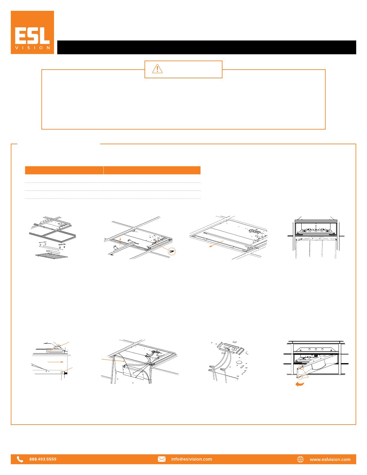
2Install LED panel end brackets to
each end of the existing fixture
by gently lifting it and placing LED
panel end brackets between the
fixture and T-grid. If needed, to
reduce space between the fixture
and T-grid, install side brackets in
the gap. There are two tabs that
allow placement of the side brackets
into the slot of the end brackets.
6Hook the safety cables into
the holes positioned in the
end brackets.
3Secure the LED panel brackets
to the existing fixture using the
provided #8x1/2" self-drilling screws.
Retrofit Installation
1Prior to installation, disconnect
power to the fixture. Remove
the existing hardware, leaving the
supply and ground leads.
5Slide the door assembly
body horizontally to the end
of the slots.
4Locate the door assembly
body, and place onto the
keyholes of the end brackets.
hinges
locking latches
safety
cable
keyhole
840 SERIES
Troer Retrofit Installation Guide Page 1 of 2
WARNING
1. To avoid electric shock, disconnect power at source prior to installation.
2. The installation should be performed by qualified electricians or lighting technicians.
3. Before conducting any installation, maintenance, or removal, disable all power.
4. Do not touch the fixture while it is in service.
5. If there is any problem with the fixture, turn off power and DO NOT attempt repair unless
you are a qualified technician or the customer service member.
7Use the provided wire caps to
connect the wire leads of the
troer kit to the main power leads as
shown in Wire Diagram 1.
8Secure the door assembly body
by locking the latches riveted to
each end of the door frame.
HOUSING DESIGNATION OVERALL INNER DIMENSIONS
2' X 2' 24.02" (L) x 23.94" (W) x 3.07" (H)
2’ X 4’ 48.03" (L) x 23.94” (W) x 3.07” (H)
1’ X 4’ 48.03” (L) x 12.00" (W) x 3.94" (H)
Notice:
The existing fluorescent housing must be larger than those in the table below:


