TROFFER RETROFIT RTLED 1X4 2X2 2X4
LED EMERGENCY BATTERY BACK UP INSTALLATION INSTRUCTIONS
Thank you for buying RAB lighting xtures. Our goal is to design the best quality products to get the job done right. We’d like to hear your comments.
Call the Marketing Department at 888-RAB-1000 or email: marketing@rablighting.com
CLEANING
CAUTION: Be sure xture temperature is cool enough to
touch. Do not clean or maintain while xture is energized.
1. Clean polycarbonate lens & xture with non-abrasive
cleaning solution.
2. Do not open xture to clean the LEDs. Do not touch the
LEDs.
TROUBLESHOOTING
1. Check that the line voltage at xture is correct. Refer to
wiring directions.
2. Be sure the xture is grounded properly.
Note: These instructions do not cover all details or variations in equipment nor do they provide for every possible situation during installation, operation
or maintenance.
RTLED EMER IN 0918
Easy Answers
rablighting.com
Visit our website for product info
Tech Help Line
Call our experts: 888 722-1000
e-mail
Free Lighting Layouts
Answered online or by request
© 2018 RAB LIGHTING Inc.
Northvale, New Jersey 07647 USA
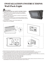
WIRING
CAUTION: THIS IS AN EMERGENCY BATTERY BACKUP
FIXTURE. Voltage could be present in Battery. To prevent
high voltage from being present on output leads, inverter
connector must be open. Do not join inverter connector
until installation is complete and AC power is supplied to
the emergency ballast.
NOTE: Make sure that the necessary branch circuit wiring is
available. An unswitched AC source of power is required. The
emergency ballast must be fed from the same branch circuit
as the AC ballast.
Do not use any supply voltage other than those specied
below.
1. Connect the UNSWITCHED black xture lead to the HOT
supply lead.
2. Connect red and black lead together, if not using a
switching method.
3. If switching, connect SWITCHED red lead to a switch.
4. Connect the COMMON xture lead to the COMMON
supply lead.
5. For 0-10V Dimming, connect DIM (+) purple lead and DIM
(-) gray lead to 0-10V dimmer. Do not connect the yellow
lead.
6. Connect the GROUND wire from xture to supply ground.
Do NOT connect the GROUND of the dimming to the
output.
7. All unused leads must be capped and insulated.
8. After installation is complete, supply AC power to the
emergency ballast and join the inverter connector.
9. At this point, power should be connected to both the
AC ballast and the emergency ballast, and the Charging
Indicator Light should illuminate indicating the battery is
charging.
10. A short-term discharge test may be conducted after the
emergency ballast has been charging for one hour. Charge
for 24 hours before conducting a long-term discharge test.
Refer to OPERATION.
OPERATION
1. When AC power is applied, the charging indicator light is
illuminated, indicating that the battery is being charged.
2. When power fails, the emergency ballast automatically
switches to emergency power (internal battery),
operating at reduced illumination. The emergency
ballast supplies 7W of power (measured at nominal
battery voltage) at a maximum rated current of 270mA
with a maximum voltage of 50VDC in emergency mode
for a minimum of 90 minutes.
3. When AC power is restored, the emergency ballast
automatically returns to charging mode.
MAINTENANCE
Although no routine maintenance is required to keep
the emergency ballast functional, it should be checked
periodically to ensure that it is working. The following
schedule is recommended:
1. Visually inspect the charging indicator light monthly. It
should be illuminated.
2. Test the emergency operation of the xture at 30-day
intervals for a minimum of 30 seconds.
3. Conduct a 90-minute discharge test once a year. Fixture
would operate at reduced illumination for a minimum of
90 minutes.
To reduce the risk of electric shock, disconnect both normal and
emergency power supplies and converter connector of the emergency
ballast before servicing. Do not attempt to service the emergency
ballast. The use of accessory equipment may cause an unsafe condition.
Do not use this product for other than intended use. Refer any servicing
indicated by these checks to a Qualied Service Personnel.