Page is loading ...

g
A
v
-
a
c
c
-
o
=
l-
6
l-
tr
\t/
AUililDililr@
ftill-ill
coMMUNICATIONSPTYLTo
www.audiotelex.com
TX8201
8
Channel
Stereo
Mixer
with
6
Direct
Outputs
A
AIJSTPAI IAN
MAF
3
Arditv
Endor-il
w
Audio
Telex
Communications
Pty Ltd
ACN 001345482
lncorporated
in
NSW
NSW
& ACT
QLD
& NT
vtc
149
Beaconsfield
Street
Private
Bag
149
Silverwater
NSW 2128
Australia
Ph 02 9il714',1
Fax 02 9648
3698
42
CommercialRoad
PO
Box 871
Fortitude
Valley
QLD
4006
Ph 07 38521312
Fax 07 32521237
221277 Middleborough
Road
Box HillVlC
3128
PO Box
151
Blackburn
South VIC
3130
Ph
03 9890 7477
Fax
03 9890 7977
WA
SA
TAS
299 Fitzgerald
Street
West Perth
WA 6005
PO Box
404
North
Perth
WA
6906
Ph 08
92284222
Fax 08
92284299
Electronic
Concepts Pty Ltd
76 George
Street
Thebarton
SA
5031
PO Box
7034 Hutt
Street
Adelaide
SA
5000
Ph
08 82349444
Fax 08 823494tr.1
K W McCulloch
Pty
Ltd
54a Albert
Road
MoonahTAS
7009
Ph
03 6228 6373
Fax
03 6278 1063
New Zealand
Unit B,
11 Piermark
Drive
PO
Box
512
Albany
NZ 1331
Ph
09 4159426
Fax
09 415 98il

TX8201 Stereo Mixer with
Direct
Outputs
Product Description
The TX8201 is
a single
rack height,
8 channel stereo mixer suitable
for
desk or
19" rack mounting. The TX820l
has 6
balanced
microphone
or
line
inputs and 2 stereo auxiliary inputs. Each
input
channel
has individual
bass,
treble and
pan
controls.
The
first 6 channels
feature
a line level direct output which can be used to
feed
additional amplifiers,
mixers or recording devices.
An
internal
jumper
allows the first 6 inputs to be removed from the master lefl/right outputs while still
retaining their
direct output
function. The TX8201 features in-built VOX muting
and
a4 tone
generator
with Alert, Evacuate, Pre-Announce and
Bell
tones.
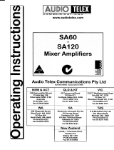
Front Panel Controls
O
O
O
tAl,Dloliillll
ol
..^""."..
rx 820r
MiC/Line
Gain:
The first
6
inputs are labeled Mic.Line I
to
Mic.Line 6 respectively and should be adjusted to
provide
the required
mix level for
each
individual
channel. Start with the controls set to Level 0 and tum the controls clockwise until the desired mix level
for
each channel
is reached.
Each of the 6 inputs is equipped with a mic/line selector dip switch which is located inside the unit
(see
the
'Internal
Adjustments'
section of this manual for more details). Please ensure that this switch is in the correct
position
for the
type of
input
(mic
or
line)
that
you
are connecting to each channel. The input sensitivity when in the
mic level
position
is lmV
(for
a I Volt
output).
The
input sensitivity when in the line level
position
is 330mV
(for
a
I Volt
output)
StefeO Line Gain: The 2 auxiliary input channels
are
labeled
Stereo
Line
7 and Stereo Line 8. These controls should be adjusted
to
provide
the required mix level for
each individual auxiliary channel. Start with the controls set to Level 0 and tum the controls
clockwise until the desired mix level for
each
channel is reached. The
sensitivity of auxiliary
inputs
7
and
8
is 180 mV
(for
a
I volt
output).
Mastef Left & Right Output The master Left and fught controls should be adjusted to set the overall
mixer level for
each
output channel based on the individual levels
already set
via
the
input channel
gain
controls. Start with the output controls set at
approximately the Level
5
position
and adjust clockwise for more output
level
or
counter-clockwise for less output
level.
Pan COntlOl: Each input channel has
a
recessed
(screwdriver
adjustable)
pan
control. The
pan
control determines
what
proportion
of each
input
channel will be sent to either of the Left or Right output channels.
Setting the
pan
control
in the centre
position
will send
equal signal
levels
to both the Left and Right master outputs. Turning the
pan
control
in a clockwise direction will send
progressively
more
signal to the
Right
output channel and less to the Left output channel.
Tuming the
pan
control
in a counter-clockwise direction
will send
progressively
more
signal to
the
Left output channel and
less to the fught output channel. The
pan
control allows the TX820l
to
be used
in dual zone
applications.
BaSS
TOnal COntfOl: Each input channel has
a
recessed
(screwdriver
adjustable) bass tonal adjustment control
labeled
"Bass".
Setting this control in
the centre
position
will give
a flat bass
response. Adjusting
the bass control
in
a
clockwise direction will
provide
up to 12 dB of bass boost
@
100 Hz. Adjusting the bass
control
in a counter-clockwise direction will
provide
up to
12 dB
of bass cut
@
100 Hz.
Treble
TOnal COntfOl:
Each input
channel has a
recessed
(screwdriver
adjustable) treble tonal adjustment control labeled
"Treble".
Setting this control in the centre
position
will
give
a flat treble response. Adjusting the treble control
in a clockwise direction
will
provide
up to l0 dB of treble boost
@
lOK Hz. Adjusting the treble control in a counter-clockwise direction
will
provide
up to 10
dB of treble cut
@
lOK Hz.

VU Metef: An 8 segment LED VU meter is provided
for each of the master Left and Right outputs. The VU meters indicate
output
signal level from
-21
to
+3
dB. For normal
operation the
LED's
should rarely oscillate in the red zone. If the LED's in the red
zone are
lit continually, then the
output
level
controls should be tumed counter-clockwise to reduce the
output
level. Too much
output level
can
cause signal distortion
and a mismatch with the device that
the
mixer is
driving.
The far left,
amber LED on each the VU meters
is for
indication
that AC
power
is
switched ON to the unit only.
Headphone
Output Socket A 714- TRS
stereo socket
is
provided
for
the connection of monitor headphones. The
output
level
to
the headphones
is a nominal 3 volts
@
600 ohms and is connected before the master output level controls. Adjusting
the master
output level controls will not
effect
the headphone
output level.
POWef
SWitCh: A rocker switch turns AC mains
power
ON and OFF to the TX820l. A
power
ON state is indicated
by the amber
LED
on each of the VU meters.
Rear
Panel
ffifOitt5oll3t;rlrit
3 Pin IEC AC Mains Power
lnlet. The operating voltage is
240 VAC
@
50 Hz
or
ll0
VAC
@
60 Hz. The AC
power
voltage level is not
externally user adjustable
but is factory
pre-set.
The inlet is
equipped with an in-built AC
fuse holder fitted with
a 1
Amp
fuse
plus
a spare. Power
consumption is 15 VA.
I Please ensure that the mains
power
cord is disconnected
before
attempting
to check or replace
this fuse.
Tone
Generator Barrier
Strip. The
TX820l includes
a
four
tone
generator
module.
The tones available include
Alert,
Evacuate, Pre-Announce
and Bell. The four
tones may
be activated via a simple contact
closure. To activate
a tone,
just
short
out the
common
terminal with the
terminal labeled with
the tone that
you
want to use. When
activated,
any of the four tones will
mute all
inputs except for
channels I and2. While
the tone
generator
function is
(as
default) set up
to be
present
on both the master
outputs and
the direct
outputs
(of
channels l-6),
it can be disabled for
all or any of the direct outputs via
an internal dip switch
(see
the 'Intemal
Adjustments'
section of this manual for
more details).
A trim
pot (R104),
which is located
on the
pcb
behind the left channel
master
output, may
be adjusted to
vary the
level
oftone
generator
output.
Left
Channel
Output Gonnection rnis is
an active balanced XLR connection
with a nominal level of I volts
@
600 ohms.
The
pin
connections are;
pin
#l-earth;
pin#Z-active (high,
+);
pin
#3-active
(low,
-).
Right
Channel Output Connectiofi.
This is an active
balanced
XLR
connection with a nominal level
of
I volts
@
600
ohms.
The
pin
connections
are;
pin
#1-earth; pin
#2-active
(high,
+;;
pin
#3-active
(low,
-).
Dual
RCA Sockets
For Output To
A Stereo Tape Recorder. Nominal
500mV
@
llKohms. The
top connector
is
the left channel
output while the
bottom connector is the right
channel output. The tape outputs
are connected before the master
Left
& Right output level
controls so the
tape output level is not
affected by adjustments to the master
level controls.
Dual
RCA Sockets
For The 2
Stereo Auxiliary
lnputs. The top connectors
are for the Left
channel auxiliary inputs
while
the bottom connectors
are for the fught
channel auxiliary inputs. Reading from
Left to Right
across the rear
panel,
the
connections are for
auxiliary inputs 8 and
7.
6 Active Balanced
XLR Sockets For
Microphone or Line lnputs.
Each XLR input is switchable
to be either
balanced mic
or line
(via
an internal dip switch,
the location and setting
of
which
is explained in the
'Internal
Adjustments' section
of
this manual).
When set to mic level,
the mic input
sensitivity is lmV
(
for
a
I
Volt output). When
set to line level, the input
sensitivity
is 330 mV
(for
a 1 Volt output). Pin
connections
are:
pin
#l-earth;
pin#2-active (high,
+;;
pin
#3-active
(low,
-).
Phantom
power
of
+15
volts is
available on
all 6
XLR
inputs. An intemal phantom power
ON-OFF switch is
provided
for each
channel.
The
default
setting
is

ON
(See
the 'Intemal
Adjustrnents'
section
of this manual for
more details).
Reading from
left to right across
the rear
panel,
th
connection for the
XLR mic/line inputs
are 6,
5,4,3,2, & I respectively.
Direct
Outputs.
A unique feature
of the TX820l
is
the individual
direct output available
for each of the first
6 channels.
Th
direct outputs
are accessed via
balanced TRS
l/4"
sockets for each
channel. The level
of each
output
is
1 Volt
(nominal).
lntemr
jumpers
(JPl)
allow
signal from
any of the fust
six
channels to be
disconnected from
the main leff/right
oueuts
(See
the'Intemi
Adjustments'
section
of this manual for
more information).
VOX
MUtin$. Priority
muting is
provided
for
channels I and2. Both
channels have
equal
priority
and will mute
channels
3-8 whe
signal
is present.
The muting
function
may be
disabled by moving the
jumper
labeled
JP2
(located
on the
pcb
behind the
channel
volume
control).
ON and OFF
positions
are clearly
indicated on the
pcb
beside the
jumper.
The unit ships from
the factory with
mutin
enabled
(JP2
-OFF)
-
that's right,
OFF; it is
a muting disable
function, not a muting
enable
frrnction.
When
channels I
and 2
ar
disconnected
from the main
leff/right
ouputs, the
muting frrnction is
automatically disabled.
TOng
GgngfatOf. A
four tone
generator
is
built into the TX820l.
The tones
available are Alert, Evacuate,
Pre-Announce
an
Bell. All
four tones
can be activated
individually
via rear
panel
contact
closures. All tones
mute channels
3-8. Tones can
be disable
from
the direct outputs
via an internal
dip switch
(See
the
'Internal Adjustnents'
section
of this manual for more
information).
A trir
pot
(R104)
which is located
on the board
behind the left
channel master
output may
be adjusted to vary
the level of tone
generatc
output.
lnternal Adjustments
g
The following
adjustments involve
access
to the inside of the TX8201.
Adjustment
should only be
attempted
by
qualifred
technician. Always
turn offthe
AC
power
and
remove
the AC
power
cord
before attempting
to access the inside
of th
TX820r
Master
Left/Right
and
Direct
Out Assignment.
A
jumper
labeled JPI is
provided
for
each of the first
6 channels. Th
jumpers
are
lqcated
near
the front
of the unit. When
in the
ON
position,
signal from
that channel
is fed to both the master
outputs
an
the
direct outputs.
When
the switch is in
the OFF
position,
signal from
that channel is fed
to the
direct line level output
only.
Mic/Line
Switch
for
Channels
1-6. A four
position
dip switch is located
on the main
board behind each input.
To
ser
channel for
microphone
level,
set switches I
ard2
(MIC)
to the
ON
position.
To
set a channel for line
level, set
switches I and 2
to th
OFF
position.
The
unit ships
from the faciory
set to mic
level.
Tone
Generator
to Direct
Output
Defeat
Switch. Sigrral from the
tone
generator
can be
removed
from
each direc
output via switch #
4
(TG)
on the internal
dip switch
per
channel. When in the
ON
position,
the
tones
(when
activated)
are
fed
to th
corresponding
direct output
as well as the
master Lefl/Right
outputs. When the
switch
#4
is set
to the OFF
position,
the tones
are onl
present
at the Master I€ft/Right
outputs.
A trim
pot
(R104)
which is located
on
the
board behind the left
channel master ouput
may b
adjusted to vary the level
oftone
generator
output.
Phantom
Power Defeat
Each
of the )(LR inputs has
access to
+l5v
DC
phantom
power.
Phantom
power
is
selected
vi
switch #
3
(PP)
on the internal
dip switches
mentioned
above. When switch #
3 is in the ON
position,
+l5v
phantom power
is
availabl
on
the
XLR
input.
Care should be taken
to disable
phantom power
before
connecting any unbalanced
or
line
source. The factory
defau)
position
is
with
phantom
power
set to
the ON
position.
MUting Defeat.
The muting
firnction
can be disabled
by
moving
the
jumper
labeled
JP2
(located
behind channel 8 volum
control). In
the ON
position
muting is
disabled, in
the OFF
position
muting is
enabled
(go
figure!).
The unit ships from
the factory wit
muting
enabled, ie
the
jumper
is
set to the
OFF
position.
When
channels I and 2
are
removed
from the main leff/right
output, th
muting
frrnction is automatically
disabled.
Looking for
something
worthy to connect
to the inputs and outputs
of
your
new TX8201? Well,
please
call
you
nearest Audio
Telex Communications
office for referral
to
your
closest authorised
dealer or for more
informatiot
on the full
selection
of our compatible
sound system
products.
/