Page is loading ...

A 4425A
Public Address Mixer
Operating Instructions
®
www.altronics.com.au
Mixer Overview
Description
This Redback
®
8 channel mixer has been designed to meet the
requirements of professional public address installations. Its many
features makes it ideally suited for use in shopping centres,
gymnasiums, places of worship, office complexes, board rooms,
council chambers, court rooms etc.
Inputs and Outputs
Inputs 1-6 can be configured for balanced microphone or line use as
desired. XLR and dual RCA sockets are provided for each of these
inputs. Inputs 7 & 8 are dedicated line inputs provided with dual RCA
sockets and variable muting/ducking level. Outputs are 600Ω/0dBm
XLR balanced or dual RCA sockets for record/tape out.
Input Configuration
Inputs 1-6 include an individual 4 way dip switch enabling selection of
mic or line input operation, adjustable line input sensitivity (100mV or
1V), mic or line operation of priority/VOX muting (see below for
priority details) and phantom power on/off.
A DIP switch is provided for inputs 7 & 8 enabling the adjustment of
the input sensitivity (100mV or 1V).
Front Panel Controls
The front panel includes individual volume controls and tamper proof,
screw driver adjust, treble and bass controls for each input channel.
A LED VU meter and a headphone socket are provided.
Priority and Muting
The mixer incorporates three levels of priority. Inputs 1,2 and 3 will
operate the priority/VOX muting regardless of the input configuration
ie: both microphone and line inputs will operate the priority/VOX
circuit if this function is selected ON for that input. This is
particularly useful when an input is set for line use, as it enables
telephone paging, radio microphone, emergency tones, jukebox or
similar to mute background music on other inputs.
Three level priority operates as shown:
Input 1 Priority 1 – mutes inputs 2 - 8,
Input 2 Priority 2 – mutes inputs 3 – 8,
Input 3 Priority 3 – mutes inputs 4 – 8,
Inputs 4-8 are mixed. If the priority function for inputs 1-3 is turned
off, then inputs assume no priority and its output will be mixed with
inputs 4-8 ie. if all priority functions are switched OFF then all inputs
will be mixed.
When fitted the optional A 4573 assumes priority 2.
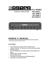
Adjusting VOX muting sensitivity
The adjustment pots are located internally. See page 2 for diagram.
1. Switch off the unit and remove the 240V mains lead and 24V in
from the rear.
2. Remove the 6 x M3 screws from the lid and remove the lid.
3. The adjustment pots are located on the main (middle) PCB and
are marked EVAC, MIC1, MIC2, MIC3. Adjust the appropriate pot
clockwise to increase sensitivity and anti-clockwise to decrease
sensitivity.
4. Replace lid and screws and reapply power.
Optional Modules
Alert and evacuation tones are available with the installation of the
optional A 4573 tone generator.
An optional compressor/compander module (A 4426) can be fitted
internally to inputs 7 and 8. This is desirable when using CD/DVD
players as a BGM source. It maintains a consistent output level during
CD/DVD playback to eliminate constant adjustment of volume levels
from quiet tracks to louder tracks on the disc.
TABLE 1: DIP SWITCH SETTINGS
Inputs 1 - 6 (refer to DIP 1-6)
Switch Item On Off
1 Input Type Line Mic
2 Line Level 1V 100mV
3 Priority On Off
4 Phan. Pwr On Off
Inputs 7 - 8 (refer to DIP 7)
Switch Item On Off
1 Input 8 1V 100mV
2- - -
3- - -
4 Input 7 1V 100mV

REDBACK A 4425A Mixer
Page 2
Instructions For Use
Remove the mixer from its packaging and inspect for any damage. If
the unit appears to be damaged then do not operate as this may
damage the unit further.
1. Prior to installation, set input configurations as desired via the DIP
switches on rear of unit. The table below shows the various
settings.
2. Plug in a low impedance microphone into the microphone input,
or a music source (tape or Compact Disc or similar) into the line
input.
3. Connect the mixer to an amplifier using a suitable cable. See
figure 2, Connection Details.
4. Turn all controls fully down and then switch the mixer and
amplifier on.
5. Turn up the level control associated with the input that you are
using to about half way. Talk into the microphone (or play some
music) and adjust the Master level to achieve the required level.
For the best sound performance turn the input level control to a high
setting (say 3/4 ) and use the Master as the volume control. Use the
other input level controls to set the required mixing ratios. Adjust the
bass and treble controls to get the desired sound. For best
performance when using long lines between microphones/mixer and
or amplifier use balanced lines. These reduce noise or hum that may
be induced into the cables. Note that a balanced line uses three wires
(two signal wires and one screened earth wire or shield) where an
unbalanced cable uses only one signal wire and a screened earth.
See the connection details (figure 2) for wiring up plugs etc.
Do not tamper with the unit. Warning Mains Voltage is Present
Inside. Leave servicing to qualified personnel.
Installing the tone generator
A 4573:
1. Remove lid from unit
2. Unscrew tone generator plate from rear panel
3. Locate tone generator 10 way header on board (this is located at
the rear of the main board)
4. Connect ribbon cable header to the 10 way header on the board
of mixer.
5. The tone generator is held in by way of 2 screws (supplied)
through the rear panel (via the same holes that the tone genera-
tor plate was attached).
6. Refit lid and secure with screws.
NOTE: Tones are operated by closing contacts and remain operat-
ing whilst contacts are closed. The A 4573 assumes priority 2
when installed
Installing the compressor
A 4426:
1. Remove lid from unit
2. Locate tone generator 10 way header on board (this is located in
the middle of the main board)
4. Connect ribbon cable header to the 10 way header on the board
of mixer.
5. The compressor board is mounted onto 4 plastic standoffs locat-
ed on the main printed circuit board.
6. Refit lid and secure with screws.
A 4426 header
A 4426 standoffs
A 4573 header
A 4573 & A 4426 Header Locations
MIC2
EVAC
MIC1
MIC3
VOX Muting
Sensitivity
Adjust

REDBACK A 4425A Mixer
Page 3
1
2
3
Signal
Input
Unbalanced
1
2
3
Signal
XLR Mic
Input
From Microphone
Input
Balanced
1
2
3
Output
Unbalanced
Signal
RCA
Shield
For Stereo
Amplifiers
RCA
XLR Line
Output
1
2
3
XLR Line
Output
1
2
3
Shield
XLR Amp
Input
Output
Balanced
Shield
XLR Mic
Input
Shield
From Microphone
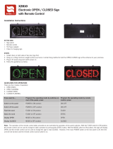
Figure 2.
Connection Details
Microphone Connections
Connector Type:..................XLR 3Pin Female
Pin 1:.....................................................Earth
Pin 2:...............................Signal Inphase (hot)
Pin 3:......................Signal Out of Phase (cold)
Output Connections
Connector Type: .....................XLR 3Pin Male
Pin 1:.....................................................Earth
Pin 2:...............................Signal Inphase (hot)
Pin 3:......................Signal Out of Phase (cold)
A 4425A Rear Panel Layout
DIP 7 DIP 6 DIP 5 DIP 4 DIP 3 DIP 2 DIP 1
Trouble Shooting
Fault/Symptom: No Sound
• Check that there is power on both the mixer and power amplifier. The
mixer has a LED light to indicate if there is power.
• Check input and master volume controls are turned up.
• Check all lead connections
Fault/Symptom: When Paging the Music is Not Muted
• Set the VOX Muting DIP switch to “ON” for that input.
• Adjust the muting level control (inputs 7-8)
Fault/Symptom: Microphone Does Not Work
• The microphone may need phantom power. If so set the Phantom Power
DIP switch on that input to “ON”.
• Check microphone volume is turned up.
Input 7-8 no muting
• Check muting level adjustment on the rear panel
Line level too low
• Check sensitivity DIP switch settings. Set to correct configuration ie:
100mV or 1V (see table 1 for DIP switch details)

REDBACK A 4425A Mixer
Page 4
Proudly Assembled in Australia
Distributed by Altronic Distributors Pty. Ltd. Perth. Western Australia.
Phone: 1300 780 999 Fax: 1300 790 999
Internet: www.altronics.com.au
Specifications
Inputs: ..............................................6 microphone - balanced 200-600Ω
2 line - unbalanced 100kΩ
Output: ..................................................................600Ω balanced 0dBm
DISTORTION
Mic inputs:........................................................................< 0.3% @ 1KHz
Line inputs:...................................................................... < 0.3% @ 1KHz
FREQUENCY RESPONSE
Mic:........................................................................................30Hz-15kHz
Line: ......................................................................................18Hz-23kHz
S/N ratio: ..............................................................All controls min. -98dB
Sensitivity: ................................................Mic 1.25mV, line 100mV or 1V
Phantom power: ............................................................Nominal 12V DC
Output connectors: ....................................................3 pin XLR balanced
Dual RCA sockets
INPUT CONNECTORS
Mic inputs: ..................................................................3 pin XLR balanced
Line inputs: ....................................................................Dual RCA sockets
CONTROLS
Mic inputs: ....................................................................................Volume
Line inputs: ..................................................................................Volume
Bass: ..............................................................................±10dB @ 100Hz
Treble: ............................................................................±10dB @ 10kHz
Master: ..........................................................................................Volume
Indicators: ..........................................................................Power on LED
Power supply: ............................................................240V AC or 24V DC
Dimensions: ......................................................482W x 152D x 44H mm
Weight:..............................................................................................≈3kg
Colour:..............................................................................................Black
All measurements measured in respect to 1kHz reference.
*Specifications subject to change without notice
/