Page is loading ...

AMrilDiltil@
tHl-ill
c
o
-
.f-,
()
=
f-
a
g
c
(I
.f-,
ru
l-
o
CO
M M
U
N I
CATI
O N S;rlrL:rD
ACM2150
Dual
Channel
Power
Amplifier
A
A,5TFAIAN
MTOC
3
(l*,
Et&rld
ConprV
ctat|!
IIEIS
Audio
Telex
Gommunications
pty
Ltd
ACN 001345482
hcorporated
tn
NSW
NSW
& ACT
QLD
&
NT
vlc
149 Beaconsfleld
Street
Prlvate
Bag
149
Sllverwater
NSW
2128
Australla
Ph
02
9047141',
Fax
02
9648
3698
42
Commerclal
Road
PO
Box
871
Fortltude
Valley
QLD
4006
Ph
07
3852
1312
Fax
07
32521237
2U277
tlddleboriugh
Road
Box
Hlll VIC
3128
PO
Box
lSi
Blackburn
South
VIC
glg0
Ph
03 98907477
Fax
03
9890
7927
WA
SA
TAS
7164-66
Kent
Street
PO
Box
489
Cannlngton
WA
6107
Ph
08
9356
2761
Fax
08
9356
2762
Electronlc
Concepts
pty
Ltd
76
George
Street
Thebarton
SA
50gl
PO Box
7030
Hutt
Street
Adelalde
SA
5000
Ph
08
82349444
Fax
08 8234-%lt
K W
l{cCulloch
Pty
Ltd
54a
Albert
Road
lloonahTA8
7009
Ph
03
6228
e,?,73
Fax
03
6278
1063
New
Unlt
B,
11 Plermark
Drlve
PO Box
512
Albany
NZ
'1331
Ph
09 415
9426
Fax
09
415
9864

ACM21 50
150
+
150
Watt
Power
Amplifier
Product Description
The ACM2l50 is a dual channel 150
+
150 watt
power
amplifier
in
a two
rack unit
(2RLf
chassis suitable
for table or direct 19"
rack mounting. The ACM2I50 has
outputs
for 100 volt line or
4 -
8 ohms
and has an active balanced
input of lOK ohms. The
ACM2I50
will
operate
llom 240 VAC
@
50
Hz
or
ll0 VAC
@
60 Hz
(not
user
selectable, internal factory
adjustment
only,
specifo
at the time of ordering). The ACM2I50 also features
auto-sensing fan cooling
and
over
temperature
protection.
The
maximum recommended load
for the ACM2l50 is
65 ohms
per
channel for
100 volt line operation and
4
ohms
per
channel
for
low impedance operation.
Front
Panel Controls
OUtpUt
Level:
The input level controls are unlabelled,
recessed
(screwdriver
adjustable)
and
are
located in the
centre of
the front
panel.
Turning a control clockwise
will increase the output of the
particular
channel of
the ACM2I50 towards it's
maximum output
level while turning the control counter-clockwise
will decrease the output
level. Adjust this conkol
for the
desired output
level depending on the level of the input signal
(from
a mixer or other sigrral source).
The factory
default setting
for this control
is I volt input will supply full load into
4
ohms.
POWef SWitCh:
The
rocker
switch
located
in the
front
centre
of the
panel
turns
AC
power
on
to the ACM2I50.
Rocking
the
power
switch to the right
to
turns the AC
power
'on'.
When
the
AC
power
is 'on', the "CH A" and
*CH
B" LED's will
glow
in the amplifier status
display window.
Cooling
Fans
(Air
lntake):
tre cooling
fan is
temperature sensitive
and will only switch on
when
the temperature
of the ACM2150
had
reached a
pre-determined
range. The fan
will
stay on
and
only
switch offagain once the ternperature
of the
amplifier
has fallen
below a
pre-determined
level. So, the fact
that the fan is not operating at any time
(and
most noticeably
to the
operator
at turn-on)
does not mean that the amplifier
is faulty in any way,
just
that
it is
operating
within a temperature range
that
does
not need
fan cooling for adequate
heat
dissipation.
If
the
ACM2I50 is
operating
continually at conservative
levels
and
proper
load
conditions, it is
possible
that the
cooling
fan will not switch on at any time during
normal operation. Whan operating,
the
fans cause air
flow from the front to
the
rear of the
amplifier.

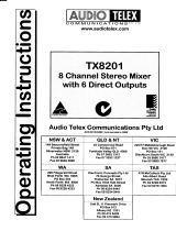
Amplifier
Status Display
Window
The
status
display
window
highlights
the
operating conditions
of the
ACM2l50.
F-F
ll
()(4
-,
I
I I I
I I I I
I
lll l
2r ra rJ t2
9 6 5
O
tt
l{[I1 TIIP
TAULT
--
I
I I
I I T I T
I
Ul!
2l
16 t5
t2
9
G| 5 O
+t
l.
Channel
A
/ Channel
B: These
LED's
glow
green
if
AC
power
is
switched
on to the
ACM2l50.
High
Temperature:
This red
LED
glows
if
the fans have
failed
and
the
amplifier
has
been
shut
down
by its,
temperature
control
circuitry.
If this
LED
is
glowing
and the
fans have
not failed,
it
means
that
the amplifier
is
operating
in
an ambient
environment
that
is naturally
too
hot for
fan
cooling to
make any
difference
to
the
temperature
of the
amplifier.
3.
Fault:
This LED
glows
red if
there is
DC
present
on the ourput
(speaker
lines)
in
which
case
the speakers
will
be
internally
disconnected
from
the amplifier
stage.
4-
Output
Level
VU
MeteIl Two 9
segment
LED VU
meters
are
provided
to
give
an indication
of the
output
signal
levels
of each channelof
the
ACM2I50
from -21
to
+3
dB. For
normal
operation
the
LED's
should
oscillate
in
and
out
of
the red
zone' If the
LED's in
the red
zone are lit
continually,
then
the
output
level
control (or
the level
of the input
signal
to
the
ACM2I50)
should
be adjusted
to reduce
the
ouput level.
Too much
output
level
can
cause
distortion
and
possible
damage to the
connected
speaker
system.
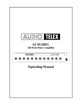
Rear
Panel
Connections
l'
3
Pin
lEC,
AC
Mains
Power
lnlet The
operating
voltage
is
240 VAC
@
so rlzor
n0
VAc
@
60
FIz.
The
AC
power
voltage
level
is not
externally
user
selectable
but
is factory
prsset
(via
transformer
selection).-Ttt"
ittl"t
i,
equipped with
an
inbuilt
AC
fuse holder
fitted with
a 6
Amp slow
blow
frse
plus
one
spare
fiue.
power
consumption
is
300
VA.
Please
ensure
that the mains power
cord is
disconnected
before
attempting
to check
or replace
this
fuse.
qaQ"a
!-::::.'.::::-::
r---:--r-:
r::::-_:(:=
-)--
(-_=t:l-l
FE'Egtnq
l.<
-r
.*
-nl
a"gQ"g
:
G-
c-
-)
Continued
ouo
p"g"
$

2.
Output
Selector
Switch:
This
selector
slide
switch
is used
to select
the output level
desired.
Before
adjustir
this
switch
in
any way
please
make
sure
that
the AC
power
switch is
in the
"off'position.
Any selection
made
is
common
both
channels
and
they
cannot
be
selected
independently
of each
other.
To select
an
output
oi
100
volts
RMS
(100
volt
lir
or high
impedance)
move
the
switch
to
the left
position
when
looking
directly
at the
iear
of the
amplifier.
To
select
r
output
of 4-8
ohms
(low
impedance)
move
the
switch
to the right
position
whar
looking
directly
at the rear
of the amplifie
Note:
If
the incorrect
setting
is
used
this
may
cause serious
damage
to
the amplifier
and/or
speakers
and
void
ar
warranQr
claim.
Refer
to
your
authorised
dealer
or
Audio
Telex for
further
information.
Output
Terminal
Strip: Reading
from
left
to right
these
connections
are
as follows:
Positive
connection
for
channel
B
output
Negative
connection
for
channel
B
output
Spare
Spare
Positive
connection
for
channel
A
output
Negative
connection
for
channel
A output
Note:
These
outputs
(channels
A
& B)
cannot
be
selected
or wired
for
bridged
mode
mono
operation.
DC
Low
Voltage
Fuse
Receptacles:
Access
the
DC
fuses
by turning
the
caps half
a turn
counte
clockwise
with
a screwdriver.
The
value
of
the fuses
is
5 Amps
slow
blow.
Please
ensure
in"t tn"
AC
power
switch
is
i
the
'off
position
and
that
the
mains power
cord
is
disconnected
before
attempting
to
check
o"
""pla""
any
of ther
fuses.
lnput
(&
Parallel
Output)
XLR
Signal
Connections:
The inputs (A
& B) to
the
ACM2I50
ar
active
balanced
@
lOK
ohms.
The
pin
configuration
of all
sockets
is
as follows: pin
#l-earth
;
pn
#2-active
(high, +);
pi
#3-active (low,
-).
The
output
socket
is
to allow
the
original
input
signal
to
be fed
on to
another
amplifier.
As-these
t\r
sockets
are wired
in
passive
parallel
for
each
channel,
the
failure
of any
one
amplifier
will
not
affect
the
signal
flowin
through
that
amplifier
to
another
amplifier.
3.
4.
Fuse
Sizes
ACltl2150
Amplifier
tiains
240
VACI
6AmperesStowBlow
DG:
5
Amperes
Slow
Blow
Looking
for
something
worthy
to
connect
to
the
inputs
and
outputs
of
your
neu
ACtl2150?
Well,
please
call
your
nearest
Audio
Telex
Communications
office
for
referral
to
your
closest
authorised
Dealer
or for
more
information
on
the
ful
selection
of
our
compatible
sound
system
products.
/