Page is loading ...

g
o
-
.f-,
C)
=
l-
.f-,
a
g
g
-
.l-l
$
l-
o
AUililDililr@
IH
llr
COMMUNICATIONSPTYLTD
www.audiotelex.com
SA6O
&
SA12O
Mixer
Amplifiers
3
Quditv
Endorse6
"TH;|H
Audio
Telex
Communications
Pty Ltd
ACN
001345482 lncorporated in
NSW
NSW & ACT
QLD
& NT vtc
149 Beaconsfield
Street
Private Bag
149
Silverwater NSW
2128
Australia
Ph
02 9647141',
Fax 02 9648
3698
42 CommercialRoad
PO Box 871
Fortitude Valley
QLD
4006
Ph 07 385213'12
Fax0l 32521237
221277 Middleborough
Road
Box HillVlC
3128
PO Box
151
Blackburn South
VIC 3130
Ph 03 98907477
Fax
03 9890 7977
WA
SA
TAS
299 Fitzgerald
Street
West Perth
WA 6005
PO Box
404
North Perth
WA
6906
Ptr 08 92284222
Fax 08 92284233
Electronic
Concepts Pty Ltd
76 George
Stredt
Thebarton SA
5031
PO Box
7034 Hutt
Street
Adelaide
SA 5000
Ph 08 82349444
Fax 08
82UgM1
K W McCulloch
Pty Ltd
54a Albert
Road
MoonahTAS 7009
Ph 03 62286373
Fax 03 6278 1063
New Zealand
Unit B, 11
Piermark Drive
PO Box 512
Albany NZ 1331
Ph
09 4',,59426
Fax 09 415
9864

SA60 Mixer Amplifier
SA1
20
Mixer Amplifier
Product Description
The 5460 is
a 60
watt,
6 channel mixer
amplifier and similarly
the SAl20 is a 120 watl,
6 channel mixer amplifier. Both
models
operate from240YAC@50H2(or
1l0VAC
@60Hzwithfactorymodification)or24
VDCviaanextemalbatterysupplyandboth
can
either be desk or rack mounted. Both
are 2 standard rack
units high and standard rack width
of
482mm,
for table mounting
rubber
feet
are supplied but these
should be removed if rack
mounting is intended. Both
amplifiers will deliver their specified
wattage into
loads
of
4
or 8 ohms,70
or 100
volt
line. both
models feature six dual
purpose
inputs, XLR balanced mic input
and dual RCA
aux/line
level
inputs. Channel
6 only has
a
higher level
aux/line level input
to enable it to
accept a CD
player
or similar high level
inputs. The
SA series feature output
overload
protection,
a
TRS
insert
point
between
the mixer and amplifier
stages
for
easy insertion
of a
graphic
EQ, FBX Feedback
Exterminator
or similar, intemal
heat sinking and
a strong steel
chassis.
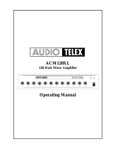
Front Panel
Gontrols
&
Fladlrfa
sA 1 20
6ts6d666-
(SAl20
shown. The
5,4'60 has identical front
panel
controls)
I.
Dual
Microphone/Line
Gain Controls:
The 6 dual mic/line
input controls
are marked Ch I through
Ch 6
and
should be
adjusted to
provide
the required
mix level for
each individual channel.
Start with the controls
set to level 0 and
tum the
controls
slowly clockwise
until the desired mix for
each chamel is obtained.
BaSs
Tonal ContfOl:
Setting this control in
the centre 'ozero"
position
will
give
an overall flat bass response
to the output
of the amplifier. Adjusting
the bass control in
a clockwise direction will
provide
up to
+12
dB
of bass boost
@
100 Hz. Adjusting
the
bass
control in
a counter-clockwise
direction will
provide
up
to
-12
dB of bass cut
@
100 Hz.
Tfeble TOnal ContfOl:
Setting this
control
in
the centre
o'zero"
position
will
give
an overall flat treble response
to the
output of
the amplifier. Adjusting the
treble control in a clockwise
direction will
provide
up to
+9
dB of treble boost
@
l0 kHz.
Adjusting
the treble control in
a counter-clockwise
direction
will
provide
up
-9
dB of treble
cut at 10 kHz.
MaStef OUtpUt
GOntfOl: This
control adjusts the overall output level
of the amplifier depending on the levels
set for the
individual input mix
channels as
detailed above.
Start
with
the control level set to level
0 and slowly turn the control clockwise
until the desired
output level of the
amplifier is reached.
POWef
SWitCh: This
switch controls the switching
of the AC
power
to the amplifier.
Rocking this switch upwards
fiims on
AC
power
to
the amplifier while rocking
the switch downwards
tums
power
off to the
amplifier. When in the upward
"On"
position,
the red neon in
the body of the switch will
glow.
LED Display
VU Metef: Marked in
decibel
graduations
from
-21dB
to
+3
dB, the light emitting diodes will indicate
the
volume level
at the output
of
the
amplifier. For normal
operation the LED's
glow green
as they
modulate
with the output level
of
the amplifier. If
the lights
are consistently indicating red
the amplifier is being
overdriven, resulting in distortion in the
quality
of
the audio signal.
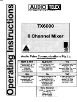
2.

Rear
Panel Connections
oo
oo
oo
oo
o
o
y,C
3
?'--r
'c
o)
't,,
\,,o
o
o
rrc
5
vrc .
Oz: O--
Ja
9-----.
ic
oj
\c
'-'o
or
@
c;
c
n/
cot a a cot 70 r00 srt20-alsl60-f
I I I I I I
^cr^s/rl^c2^s,/B
Hlr.ELrffif]
oc'|o^ s/srDc 5^ s/r
o
(SAl20
shown. The 54.60
does
not have
a 4 ohm outpuQ
t. 3 Pin IEC AC
Mains Power lnlet The
operating voltage is 240 VAC
@50Hzor
il0 VAC
@60H2.
The
AC
power
voltage is not extemally
user adjustable
but is factory
preset.
The inlet
is equipped with an inbuilt AC
fuse holder fitted
with a 4
amp slow
blow fuse
plus
one
spare. Power consumption
is 350 watts.
I
Please
ensure that the mains
power
cord is
disconnected before
attempting to check
or replace this fuse.
Z. Direct Output
ConnectiOlsl These
screw terminals allow
access to the direct outputs
of
the
amplifier. 2 spare screw
terminals
allow
for
the connection
of
various
tone module
accessories. Reading from left to right
the terminals are-
r
Low Impedance
Common
o
4
Ohms
(SAl20
only. Not on 5460)
o
8 Ohms
o
Constant Voltage Common
r
70 Volt Line
o
100 Volt
Line
.
Spare
.
Spare
Note:
The minimum impedance
level
at any time on maximum
load for 100 Volt line
should be no less
than 80 Ohms for
the SAl20
and no less
than 170 Ohms for
the 5,4,60.
24
Volts DC Power
Source Connectiolll Two post
style terminals
allow for
the connection of an external 24VDC
battery for
applications where PA
system operation is imperative.
The red terminal
post
is for connection to
the
positive (+)
terminal.
The black terminal
post
is
for connection to the negative
O
terminal. A
trickle charge circuit
provides
a maximum
300mV automatically to
a stand-by battery connected
tothe24 VDC input on the SA120
only.
DC FUSe
HOldef: Remove with
a screwdriver if access is required. DC
fuse rating is 10 Amps
Slow Blow for the
SA120
and 5 Amps Slow Blow for
the 5,4.60.
lnSeft
TRS
jack
socket insert
point (6.5mm).
Enables
a
graphic
equaliser, FBX Feedback
Exterminator or
similar
product
to
be connected. Unbalanced
insertion,
breaks
normal
connection
between the
pre-amp
and
power
amp stages of the amplifier. Tip
:
Return.
Ring
=
Send.
Sleeve: Ground.
Tape
OUtpUt 2 x RCA style
phono
output
connector for line level output. Provides
a maximum
of 350mV into lOK
Ohms,
ideal
for a connection
to most standard
tape recorders. This
output
is
sourced before the
master
gain
control
and as such,
the tape
output level
is not influenced
by the operation
ofthe master
gain
control.
Line OUtpUt
Vtate XLR style,
balanced transformer isolated
output for connection
to additional
power
amplifiers. Provides
a maximum
of 700mV.
Suitable for driving
power
amplifiers or similar
devices. Pin connections
are Pin I
=
Earth. Pin
2
=
Active Positive
(+).
Pin
3
:
Active
Negative
O.
4.
5.
6.
7.

S. Ling lnputs: Note: AIt inputs
are universal line / microphone inputs. Both
connectors can
not
be utilised for any
one
input. Six
pairs
of RCA
style
phono
input connectors
accept unbalanced line or auxiliary inputs for channels I
through 6.
Channel
6 accepts higher level inputs
such as a CD
player.
e.
MiCfOphOne lnpUtS: Note:
All inputs
are universal line / microphone inputs.
Both connectors can not be
utilised
for any one input.
Six female XLR inputs
accept 200 Ohm
balanced or unbalanced microphone inputs. Pin connections
are Pin I
:
Earth. Pin2: Active
Positive
(+).
Pin
3
:
Active Negative
(-).
Special
Facilities
Phantom
Power: Normally
supplied to
each of the six XLR microphone inputs.
Provides 18 Volts DC. An intemal
on/off
slide switch can
be
found
on the internal
circuit board
PCB6I77 to disconnect
phantom power
from all six inputs.
I
ft is necessary
to disconnect
the
power
cord and remove the tid
from the amplifier
before operating this switch.
Limiting:
The
SA series of amplifiers
are equipped with a "soft knee limiter",
which
protects
the amplifier from
overload or short
circuits. In
some cases it may be
desirable to disconnect
the limiter to obtain higher
than
rated power.
This can be achieved
by
removing
a link
on
PCB6I79,
however
this is not recommended.
Performing this
procedure
will void any warranty
claim. I It is
necessary
to disconnect the
power
cord and remove
the lid from the amplifier
before attempting this
procedure.
Optional
Accessories
g
The installation
of some of
the
following
optional accessories involves
access to the inside
of the amptifier.
Installation
should
only be attempted
by a
qualified
technician. Always
turn off
the
AC
power
and remove the AC
power
cord before
attempting to
access the inside of the
amplifier. Please
contact
your
nearest Audio Telex
oflice
for
details of
your
nearest
qualified
technician.
TOne GenefatOfS:
Four separate
tones are
available as an option via
the
ATC5488
tone
generator
board.
This
internally
mounted PCB
is easily fitted
and
plugs
directly into a
socket
provided
on the intemal
circuit board PCB6I78. Please
follow the
instructions
supplied with
the tone
generator.
When
any tone from the ATC5488 PCB
is activated all inputs will
automatically mute
except for input
one.
Tones
available on the ATC5488
tone
generator
board
are:
Evacuation Tone
(to
Australian
Standard A52220.1.2)
Alert Tone
(to
Australian
Standard A52220.1.2)
Bell Tone
Pre
Announce
Chime
Voice Operated
Muting Modules:
Two separate models
are available for the SA series
amplifiers.
They
are easily fitted
internally.
Both
plug
directly into
a socket
provided
on the
intemal
circuit board PCB6I78.
The models
are:
TX3014 Muting Module
with Priority- Provides
two levels of muting with
priority
for
channel one, which mutes all other inputs
and
secondary
priority
for
channel two, which
mutes all other inputs except for
channel one.
TX3010 Muting Module-
Provides single muting
from channel
one only.
When
activated all other channels
are
muted.
Mains 240
VAC: 5 Amperes
Slow Blow
DG:
tO Amperes Slow Blow
Mains 240 VAC:
2 Amperes Slow Blow
DC:
S Amperes Slow Blow
Fuse
Sizes SA120
Amplifier
Fuse
Sizes SA60 Amplifier
/