

VIC-RELAY
-CASSEnE
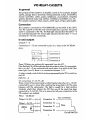
In general
The
purpose of this cassette
is
to simplify control of, for example, burglar
alarms,
garage
doors, doorlocks, heating elements, lamps, transmitters,
remote controllers, valves, pumps, telephones, accumulators, irrigation
systems, electrical tools, stop watches, ventilators, humidifiers, etc, etc.
The
cassette contains 6 relay outputs,
and
2 inputs of type optocoupler.
Connection
This
cassette
is
connected to
VIC-USER-PORT
(on
the
BACK
to the
LEFT).
Turn
the cassette so that the text
and
the lights face upwards.
The
green
socket
is
connected to the
VIC.
The
Red
light indicates
that
the inlets
1-6
are
activated (closed).
The
Green light indicates that the inlets
1-2
are
activated
(5-12v
DC
connected).
In and outputs
Outputs:
1-6.
Connections
1-12
are
connected
in
pairs to a relay
in
the
VIC
RElAY.
FIG-l.
IRE~AY/~
I
Connection 1
0
I
0
Connection 2
I
IRE~AY/o
I
Connection 3
,
0
Connection 4
I
These OUTputs
are
galvanically
separated
from the
VIC.
If
the
Red
light
(1)
is
lit
this
indicates that the socket on relay
(1)
is
connected,
that
is
to say
1-2
are
contacted with each other.
As
a result of this
if
the
same light
is
not lit, there
is
no connection between
1-2.
A relay
is
simply a switch which can
be
programmed by the
VIC
to switch on
and off.
INPUTS
1-2
Or
connections
17-18
19-20.
These constist of two optocouplers, indicating that when there
is
5-12v
DC
connected by you to some other machine the Green light
is
lit.
The
same
happens with the optocoupler.
The
light
is
caught by a light sensitive
transistor which then informs the
VIC
that one of the inputs has been
connected to
5-12v
DC.
This
is
to ensure that all your connections to the
VIC-userport
are
isolated.
FIG-2.
VIC-RElAY
I
Your
connection.
Output
+5v
DC
-(+)
I Connection 14
-->=--l
Output
-5v
DC-(-l-
Connection 15 >
I
I
--<]
Strap
OPTO.
e-'-l-o
Conneel;on
17
. 1
~(+)_!
Connection
18
__
<.
____
-'-'0\
I On/off
SWITCH

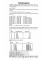
PROGRAMMING
Initiation, i.e. the programming of the different connections on
VIC's
user-
port which should
be
inlets
and
outlets respectively,
is
done
by using a
simple command.
poke 37138,63
This
puts pins
1-6
as
outputs
and
pins 7
-8
as inputs.
(se
VIC
programming
manual).
This
command should always
be
first
in
your program.
Now everything
is
ready
for a short test program. Write the following on
your
VIC.
.
10
reg=37138
20
poke reg,63
30
poke
dat
,1
40 poke
dat
,2
50
poke
dat
,4
60
poke
dat
,8
70
poke
dat
,16
80
poke
dat
,32
90
end
dat
=37136
gosub 100
gosub 100
gosub 100
gosub 100
gosub 100
gosub 100
gosub 100
rem
data
rem initiating the i/o
rem switch on lamp
(1)
rem switch on lamp
(2)
rem switch on lamp
(3)
rem switch on lamp
(4)
rem switch on lamp
(5)
rem switch on lamp
(6)
100 for t = 1 to 700 : next :return : rem wait (loop)
If
everything
is
all right, all the red lights should
be
lit
and
all outputs closed.
As
you
will
see
in
the example
above,
every relay has
its
own number.
FIG-3.
RELAY
CONNECTION
1
1-2
2
3-4
3
5-6
4
7-8
5
9-10
6
11-12
Study these figures very carefully.
FIG-4.
RELAY
ON
1
OR1
2
OR2
3
OR4
4
OR8
5
OR16
6
OR
32
POKE-DATA
1
2
4
8
16
32
OFF
ANo(63-1)
AN
0(63-2)
AN
0(63-4)
AN
0(63-8)
ANo(63-16)
AN
0(63-32)
If
relay-2 has
to
be
closed
(1)
You
have
to
write:
poke(37136),peek(37136)
or
2
If
relay-2 has to
be
opened
(0)
You
have
to
write:
poke(37136),peek(37136)
and
(63-2)
What
happens
next
is
the following,
VIC
reads
the register
as
it exists
at
PEEK
(37136) then we perform a logical
operation
'OR' with
'2'
(data
to
2

relay two
is
added to existing data).
You
can get further explanation about
the
OR
function in your VIC-manual.
As
you will be reading
about
the
OR
function, why not take the opportity to read about
the
AND
function also.
If you want to reset all the relays, just write:
POKE
37136,0
But
if
you
only want to reset a particular relay and leave
the
others
in
their
actual state
(see
fig-4 and) write:
POKE
37163,PEEK(37163)
AND
8
In
this
case
only relay no. 4 will be reset. (poke data
for
relay no. 4
==
8.
(see
fig-3).
All
the
numbers which you write
on
the
screen are
in
decimal.
These
are
then interpreted by the
VIC
as
hexadecimal or binary numbers.
Vic's user-port
is
a register containing 8 bits
(1
byte).
OK!
With
this in mind we'll have a look
at
the
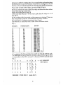
convertion table:
FIG·5.
DECIMAL
HEXADECIMAL
BINARY
1
01
00000001
2
02
00000010
3
03
00000011
4 04
00000100
5
05
00000101
6
06
00000110
7
07
00000111
8
08 00001000
9
09
00001001
10
OA
00001010
11
08
00001011
12
OC
00001100
13
00
00001101
14
OE
00001110
15
OF
00001111
16
10
0001
0000
17
11
0001
0001
Etc.
Let
us
return to
the
first example.
You
switch on relay
(1)
with
the
code
I
or
0000
0001
(as
the
VIC
sees
it).
This
data
is
placed
in
the register which
correspofldens to
the
VIC's user-port. A close up: NOTE reversed data!!
FIG-6.
0
0
0 0 0 0 0
<=
VIC
USER-PORT
WITH DATA.
R
R
R R R
R
I
I
E E E
E
E
E
N N
L L
L
L L L
P
P
A
A
A A A
A
U U
Y Y Y Y
Y Y T T
2
3
4 5 6 2
10000000 =
POKE
DATA 1 (poke
dat,l).
3

HOW
TO
READ
THE
INPUTS
To
read input no. 1
PRINT
PEEK(37136)
AND
64
If the answer = 0 then input one
is
active.
(17-18
connected
to
5-12v
DC)
All other answers mean that input one
is
not active (Without
5-12v
DC).
The
same
goes
for
input two except
for
the
'AND'
data.
PRINT
PEEK(37136)
AND
128
NOTE!
128
for
input two.
See
following example:
When input-1
has
5-12v
(1),
then "peek(37136) and
64"
= 0
When input-1
loses
5-12v
(0),
then "peek(37136) and
64"
=
64
When input-2
has
5-12v
(1),
then "peek(37136) and 128" = 0
When inpuf-2
loses
5-12v
(0),
then "peek(37136) and 128" =
128
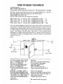
Let's
say
that the button
on
your fronf door (door bell)
is
connected fo
connections
19
and
20
(input-2). When someone
presses
if, fhe mofor fo
fhe
aufomafic door-opener starts
up
(connected via a power relay fo oufpuf-
1).
When
fhe
door
is
fully open, if
presses
a buffon which
is
connecfed fo
input-l that switches off the motor and waits a few seconds before
switching
on
the light
in
the
hall (connected via a power relay to output-2).
And lastly, the motor for closing the door, motor
fWo
which
is
connected fo
outpuf-3, sfarfs up.
FIG-7.
Lamp
19
>----<
20
Door bell.
10
POKE
37138,63 :REG=37136
20
A =
PEEK
(REG)
AND
128
30
IF
A <> 0 THEN
20
40
POKE
REG,PEEK(REG)
OR
1
50
B =
PEEK
(REG)
AND
64
60
IF
B <> 0 THEN
50
70
POKE
(REG),PEEK(REG)AND
(63-1)
80
FORT
= 1 TO 800 :
NEXT
T
90
POKE
(REG),PEEK(REG)
OR
2
100
POKE
(REG),
PEEK(REG)
OR
4
110
FORTl=l
TO 1000:
NEXT
Tl
120
POKE
REG,PEEK(REG)AND
(63-4)
200
GOTO
20
4
.~
______
~>--(17
18
Door open.
Initiation
Read
inlet
two
(door bell button)
If not pressed read again
Start door motor
R1=1
Read
inlet one
Door not fully open yet
Open! switch
off
motor Rl=O
Wait
a few seconds.
Switch
on
the light in
t~e
hall.
R2=1
Close the door, leave the light on.
Wait
a few seconds
Closed! Stop motor. R3=0
Be
ready
for
the next guest.

NOTE!
NOTE!
NOTE!
NOTE!
NOTE!
NOTE! NOTE!
NOTE!!
Please Note! That the relays which
are
found
in
the VIC-I/O can only take a
max. of
24
volts
10
watts
and
that the circuit
in
the VIC-I/O
is
not designed
for the intended load (current) which may
be
needed
for the motors
and
lamps. That
is
why
it's recommended that one
or
more
POWER
RELAYS
be
installed by
an
electrician.
To
make
VIC
see input 1 and 2 you must activate
them by applying
5-12v
DC.
This
you may take from connection 14 which
is
(-1-5v)
and
connection
15
which
is
(-5v).
Please note!
MAXIMUM
LOAD
is
50
rnA.
This
power
is
connected
in
series with some
kind
of
switch, which
will
octivote the inputs.
NOTE!
Make connections
(-)
minus
to
minus,
and
(+)
plus to plus.
'-ook
ot
bottom
of first
page
for
correct
wireing.
Next poge con loins
Ihe
beginning of future experiments, here you might
Jruw
your own diograms to
VIC-REl.
GOOD
LUCK!.
5

VIC-RELAY-CONNECTIONS
OBJECT:
DATE:
OUTPUT
-1
I
1
Ii!!
"
-1
I
2
Ii!!
OUTPUT
-2
I
3
Ii!!
"
-2
I
4
Ii!!
OUTPUT
-3
I
Ii!!
5
"
-3
I
6
Ii!!
I
OUTPUT
-4
Ii!!
7
I
"
-4
Ii!!
8
OUTPUT
-5
I
9
Ii!!
"
-5
I
10
Ii!!
OUTPUT
-6
I
11
Ii!!
"
-6
I
'"
12
N.C.
I
'"
I
DC.
(+5v.)
Ii!!
14
I
DC.
(-5v.)
'"
15
I
N.C.
'"
.
INPUT-1
I
(-)
Ii!!
17
I
-"-
-1
(+)
18
0
I
INPUT-2
(-)
19
Ii!!
I
-"-
-2
(+)
0
20
I
6

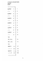
VIC
REl
and
C8M
64
Address 37136
is
changed
to
565 77
Address 37138
is
changed to 565 79


-
 1
1
-
 2
2
-
 3
3
-
 4
4
-
 5
5
-
 6
6
-
 7
7
-
 8
8
-
 9
9
-
 10
10


Ask a question and I''ll find the answer in the document
Finding information in a document is now easier with AI
Related papers
Other documents
-
Draper 121024 Datasheet
-
-
Epson MX-70 User manual
-
 Remote Technologies RPC-320 User manual
-
Tandy 1000 MS-DOS Basic Reference Manual
-
-
Apple Battery Charger ii User manual
-
-
Vector Basic Interpreter Basic 80 Reference guide
-
Star Micronics Radix User manual
